EP4257775B1 - Panneau - Google Patents
Panneau Download PDFInfo
- Publication number
- EP4257775B1 EP4257775B1 EP23194434.9A EP23194434A EP4257775B1 EP 4257775 B1 EP4257775 B1 EP 4257775B1 EP 23194434 A EP23194434 A EP 23194434A EP 4257775 B1 EP4257775 B1 EP 4257775B1
- Authority
- EP
- European Patent Office
- Prior art keywords
- profile
- panel
- edge
- tongue
- locking
- Prior art date
- Legal status (The legal status is an assumption and is not a legal conclusion. Google has not performed a legal analysis and makes no representation as to the accuracy of the status listed.)
- Active
Links
Images






Classifications
-
- E—FIXED CONSTRUCTIONS
- E04—BUILDING
- E04F—FINISHING WORK ON BUILDINGS, e.g. STAIRS, FLOORS
- E04F15/00—Flooring
- E04F15/02—Flooring or floor layers composed of a number of similar elements
- E04F15/02038—Flooring or floor layers composed of a number of similar elements characterised by tongue and groove connections between neighbouring flooring elements
-
- E—FIXED CONSTRUCTIONS
- E04—BUILDING
- E04F—FINISHING WORK ON BUILDINGS, e.g. STAIRS, FLOORS
- E04F2201/00—Joining sheets or plates or panels
- E04F2201/01—Joining sheets, plates or panels with edges in abutting relationship
- E04F2201/0107—Joining sheets, plates or panels with edges in abutting relationship by moving the sheets, plates or panels substantially in their own plane, perpendicular to the abutting edges
-
- E—FIXED CONSTRUCTIONS
- E04—BUILDING
- E04F—FINISHING WORK ON BUILDINGS, e.g. STAIRS, FLOORS
- E04F2201/00—Joining sheets or plates or panels
- E04F2201/02—Non-undercut connections, e.g. tongue and groove connections
- E04F2201/023—Non-undercut connections, e.g. tongue and groove connections with a continuous tongue or groove
-
- E—FIXED CONSTRUCTIONS
- E04—BUILDING
- E04F—FINISHING WORK ON BUILDINGS, e.g. STAIRS, FLOORS
- E04F2201/00—Joining sheets or plates or panels
- E04F2201/04—Other details of tongues or grooves
- E04F2201/043—Other details of tongues or grooves with tongues and grooves being formed by projecting or recessed parts of the panel layers
-
- E—FIXED CONSTRUCTIONS
- E04—BUILDING
- E04F—FINISHING WORK ON BUILDINGS, e.g. STAIRS, FLOORS
- E04F2201/00—Joining sheets or plates or panels
- E04F2201/05—Separate connectors or inserts, e.g. pegs, pins, keys or strips
- E04F2201/0523—Separate tongues; Interlocking keys, e.g. joining mouldings of circular, square or rectangular shape
- E04F2201/0535—Separate tongues; Interlocking keys, e.g. joining mouldings of circular, square or rectangular shape adapted for snap locking
-
- E—FIXED CONSTRUCTIONS
- E04—BUILDING
- E04F—FINISHING WORK ON BUILDINGS, e.g. STAIRS, FLOORS
- E04F2201/00—Joining sheets or plates or panels
- E04F2201/05—Separate connectors or inserts, e.g. pegs, pins, keys or strips
- E04F2201/0523—Separate tongues; Interlocking keys, e.g. joining mouldings of circular, square or rectangular shape
- E04F2201/0547—Separate tongues; Interlocking keys, e.g. joining mouldings of circular, square or rectangular shape adapted to be moved perpendicular to the joint edge
-
- E—FIXED CONSTRUCTIONS
- E04—BUILDING
- E04F—FINISHING WORK ON BUILDINGS, e.g. STAIRS, FLOORS
- E04F2201/00—Joining sheets or plates or panels
- E04F2201/05—Separate connectors or inserts, e.g. pegs, pins, keys or strips
- E04F2201/0523—Separate tongues; Interlocking keys, e.g. joining mouldings of circular, square or rectangular shape
- E04F2201/0552—Separate tongues; Interlocking keys, e.g. joining mouldings of circular, square or rectangular shape adapted to be rotated around an axis parallel to the joint edge
Definitions
- WO2005/098163A1 discloses a panel comprising coupling parts with locking elements enabling a herringbone installation pattern with only one type of panels.
- the invention relates to a panel as described in claim 1.
- Such embodiments allow to provide a locking surface with a sufficiently large surface area for efficient locking of coupled panels in the direction perpendicular to the surface of the panels.
- an upper surface of the second tongue provides the locking surface of the third profile.
- the locking surface of the second tongue is provided by a separate insert inserted in the second tongue,
- the insert is configured such that the displacement of the locking surface by a displacement or - preferably elastic - deformation of at least part of the insert during the coupling of the panel edges provides for the locking in the direction perpendicular to the surface of the panel.
- a gap is provided between the upper surface of the locking element of the first profile and the edge of the another panel.
- Such embodiments allow that milling tolerances can be reduced while still obtaining a good locking of the coupled panels.
- a gap is provided between the upper surface of the locking element of the first profile and the edge of the another panel.
- Such embodiments allow that milling tolerances can be reduced while still obtaining a good locking of the coupled panels.
- the lower lip of the first profile contacts the second profile of the edge of the another such panel in two distinct zones, wherein a gap is provided between said two distinct zones.
- Such embodiments allow that milling tolerances can be reduced while still obtaining a good locking of the coupled panels.
- the lower lip of the first profile contacts the bottom of the first tongue of the second profile of the edge of the another such panel in two distinct zones, wherein a gap is provided between said two distinct zones.
- Such embodiments allow that milling tolerances can be reduced while still obtaining a good locking of the coupled panels.
- the first profile, the second profile and the third profile extend continuously and without interruption along the edge(s) where they are provided.
- Such embodiments facilitate the milling of the profiles at the panel edges.
- the first profile, the second profile and the third profile have a constant cross section perpendicularly to the edge where they are provided, over the full length of the edge where they are provided.
- Such embodiments facilitate the milling of the profiles at the panel edges.
- first profile, the second profile and the third profile extend along the full length of the panel edge(s) where they are provided.
- Such embodiments facilitate the milling of the profiles at the panel edges.
- the first profile, the second profile and the third profile have been established by horizontal profiling. This differs from panels for glueless installation which comprise coupling parts that are profiled in horizontal and in vertical direction.
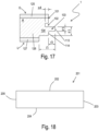
- Figure 17 shows a panel edge comprising a groove-tongue profile as in this aspect.
- the groove - tongue profile is similar to the groove - tongue profile 1 shown in figure 3 ; the reference numbers in figure 17 have the same meaning as in figure 3 .
- the panel of the example of figure 17 comprises three layers of wood 125, 126, 127.
- the layers of wood comprise a first layer of wood 125, a second layer 126 of wood and a third layer 127 of wood.
- the second layer of wood is provided between the first layer of wood and the third layer of wood.
- the continuous tongue 104 of the first groove - tongue profile 1 is provided in the second layer 126 of wood.
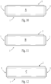
- Figures 18 - 20 illustrate embodiments of panels according to the invention.
- Figures 21 to 27 illustrate embodiments of panels not according to the invention, but comprising features of the invention.
- Figure 18 shows a panel 201.
- the panel 201 is rectangular, square or oblong.
- the panel comprises a first edge 202 and a third edge 204.
- the first edge and the third edges are provided opposite to each other.
- the panel comprises a second edge 203 and a fourth edge 205, wherein the second edge and the fourth edge are provided opposite to each other.
- Each of the first edge, the second edge, the third edge and the fourth edge comprise a profile selected from a first profile, a second profile and a third profile. Both short edges can e.g. be provided with the second profile.
- the first profile 207, the second profile 208 and the third profile 209 are configured such that a panel edge comprising the first profile can be coupled to the edge of another such panel wherein the edge of the another such panel comprises any one of the second profile or the third profile, wherein in the coupled condition a locking of the coupled edges is provided in the direction perpendicular to the coupled panels as well as in the direction perpendicular to the coupled edges and parallel with the surface of the coupled panels; and such that a panel edge comprising the second profile can be coupled to the edge of another such panel wherein the edge of the another such panel comprises the third profile, wherein in the coupled condition a locking of the coupled edges is provided in the direction perpendicular to the coupled panels as well as in the direction perpendicular to the coupled edges and parallel with the surface of the coupled panels.
- each of the first profile 207, the second profile 208 and the third profile 209 extend continuously and without interruption along the edge(s) where they are provided.
- each of the first profile 207, the second profile 208 and the third profile 209 have a constant cross section perpendicularly to the edge where they are provided, over the full length of the edge where they are provided.
- each of the first profile 207, the second profile 208 and the third profile 209 extend along the full length of the panel edge(s) where they are provided.
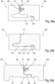
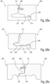
- Figures 20a-c show the edge profiles of figures 19a-c in coupled condition.
- Figures 22a-c show the edge profiles of figures 21a-c in coupled condition.
- Figures 24a-c show the edge profiles of figures 23a-c in coupled condition.
- the locking surface 215 is provided for establishing a locking in the direction perpendicular to the panel surface when a panel edge comprising the first profile is coupled to the edge of another such panel when said edge of the another such panel comprises the third profile.
- the second tongue 222 comprises a locking surface 225 for establishing a locking in the direction perpendicular to the surface of the panels in combination with the locking surface of the first profile or the locking surface of the second profile, when a panel edge comprising the third profile is coupled to an edge of another such panel comprising the first profile respectively the second profile.
- the first tongue 221 or the second tongue 222 comprises a locking element 219, which is provided for establishing in combination with the second recess 218 of the second profile a locking in the direction perpendicular to the coupled edges and parallel with the panel surface when a panel edge comprising the third profile is coupled to the edge comprising the second profile of another such panel.
- each of the first edge, the second edge, the third edge and the fourth edge are provided closer to the panel surface than the first profile, the second profile and the third profile with a closing plane 101.
- the closing planes 101 are provided perpendicularly to the panel surface. In coupled condition of two panels the closing planes of the panel edges coupled to each other contact each other or are positioned closely to each other.
- the locking surface 215 of the upper lip 215 of the first profile is provided at the upper surface of an additional groove 226 closer to the panel surface than the groove 211 of the first profile.
- the locking surface 215 of the upper lip 213 of the first profile 207 is provided as an inclined surface at the distal edge of the upper lip.
- an upper surface of the second tongue 222 provides the locking surface 225 of the third profile.
- the locking surface 225 of the second tongue 222 is provided by a separate insert 228 inserted in the second tongue 222.
- a displacement of the locking surface 225 - caused by a displacement or deformation (e.g. an elastic deformation) of at least part of the insert 228 during the coupling of the panel edges provides for the locking in the direction perpendicular to the surface of the panel
- Figure 23c shows an example of insert 228 that can be used.
- Figures 25 show another example of an insert 228 that can be used, which provided the coupling by a sliding movement of at least part of the insert.
- the panel example of figure 18 is described can e.g. at both short edges 203, 205 comprise the second profile 208.
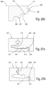
- Two edges comprising the same profile selected from the first profile, the second profile and the third profile, can comprise profiles selected from the first profile or the second profile or the third profile that differ in cross section perpendicular to the panel edge where the profiles are provided. Examples of such embodiments are illustrated in figures 26 - 28 .
- the reference numbers in figures 26 - 28 have the same meaning as in the figures 19 - 25 .
- Figure 26a-d show an example of the profiles at the four edges of a rectangular and oblong panel.
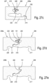
- Figures 27a-e show the edge profiles in coupled condition of the profile edges shown in figure 26 .
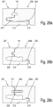
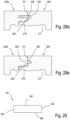
- Figure 28a-e show the edge profiles in coupled condition of another such embodiment.
- Figures 26a-d illustrate the four profiles, one provided at each of the four panel edges of a rectangular and oblong panel.
- the first profile 207 is provided at one of the panel edges.
- the first profile 207 shown in figure 26a corresponds to a large extent to the first profile shown in figure 19a .
- the second profile 208 shown in figure 26b is provided at one of the panel edges.
- Two - preferably opposite - panel edges are each provided with a different configuration of a third profile 209a, 209b.
- the two configurations of the third profile 209a, 209b differ in cross section perpendicular to the panel edge where the profiles are provided.
- the locking surface of the second tongue 222 is provided by a separate insert 225 inserted in the second tongue.
- the insert is elastically deformable such that the coupling with locking of the coupled edges in the direction perpendicular to the panel surface can be realized.
- an upper surface of the second tongue 222 provides the locking surface 225 of the third profile 209b.
- Figures 28 show - in coupled condition - an alternative for the embodiment shown in figures 26 and 27 .
- the profiles (the first profile 207, the second profile 208, and both third profiles 209a, 209b) are to a large extent similar to the ones shown is figures 26 and 27 , major difference being the different type of insert 228 being inserted in the first configuration of the third profile 209a.
- the locking is obtained via a sliding movement of the locking surface 225 during coupling.
- an elastic movement during the coupling of the related panel edges is possible of at least part of the insert 228 in the slot in the second tongue 222 in which the inert 228 is provided.
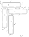
- the panels of the invention can be installed in laying patterns wherein the panels are coupled to each other under a 90° angle, e.g. as in the herringbone configuration shown in figure 9 .
- Figure 29 shows a panel 301.
- the panel 301 is rectangular and oblong.
- the panel 301 comprises a first edge 302, a second edge 303, a third edge 304, and a fourth edge 305.
- the first and the fourth edge are provided at the long edges of the panel and the second and the third edge are provided at the short edges of the panel.
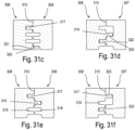
- Figures 30a-d show an example of the coupling profiles of the panel shown in figure 29 .
- the first edge 302 of the panel of figure 29 is provided with a first coupling profile 306 shown in figure 30a .
- the second edge 303 is provided with a second coupling profile 307 shown in figure 30b .
- the third edge 304 is provided with a third coupling profile 308 shown in figure 30c .
- the fourth edge 305 is provided with a fourth coupling profile 309 shown in figure 30d .
- Each of the first coupling profile 306, the second coupling profile 307, the third coupling profile 308 and the fourth coupling profile 309 extend along the full length of the panel edge where they are provided.
- Each of the first coupling profile 306, the second coupling profile 307, the third coupling profile 308 and the fourth coupling profile 309 have along the length of the panel edge where they are provided a constant cross section perpendicular to the panel edge where they are provided.
- Each of the first coupling profile 306, the second coupling profile 307, the third coupling profile 308 and the fourth coupling 309 profile extend continuously along the edge where they are provided.
Landscapes
- Engineering & Computer Science (AREA)
- Architecture (AREA)
- Civil Engineering (AREA)
- Structural Engineering (AREA)
- Finishing Walls (AREA)
Claims (12)
- Panneau, dans lequel le panneau (201) est de forme rectangulaire, carrée ou oblongue ;dans lequel le panneau comprend un premier bord (202) et un troisième bord (204), dans lequel le premier bord et le troisième bord sont prévus à l'opposé l'un de l'autre ;dans lequel le panneau comprend un deuxième bord (203) et un quatrième bord (205), dans lequel le deuxième bord et le quatrième bord sont prévus à l'opposé l'un de l'autre ;dans lequel chaque bord parmi le premier bord, le deuxième bord, le troisième bord et le quatrième bord comprend un profil qui est choisi parmi un premier profil (207), un deuxième profil (208) et un troisième profil (209) ;dans lequel le premier profil, le deuxième profil et le troisième profil sont configurés d'une manière telle qu'un bord du panneau, qui comprend le premier profil, peut être accouplé au bord d'un autre panneau de ce type ;dans lequel le bord de l'autre panneau de ce type comprend l'un quelconque des profils choisis parmi le deuxième profil ou le troisième profil ;dans lequel, à l'état accouplé, un verrouillage des bords accouplés est procuré dans la direction perpendiculaire aux panneaux accouplés, de même que dans la direction perpendiculaire aux bords accouplés et parallèlement à la surface des bords accouplés ;et d'une manière telle qu'un bord du panneau qui comprend le deuxième profil peut être accouplé au bord d'un autre panneau de ce type ; dans lequel le bord de l'autre panneau de ce type comprend le troisième profil ;dans lequel, à l'état accouplé, un verrouillage des bords accouplés est procuré dans la direction perpendiculaire aux panneaux accouplés, de même que dans la direction perpendiculaire aux bords accouplés et parallèlement à la surface des panneaux accouplés ;dans lequel le premier profil (207) comprend une rainure (211) ; dans lequel la rainure est délimitée par une lèvre inférieure (212) et par une lèvre supérieure (213) ; dans lequel la lèvre inférieure s'étend dans la direction distale jusqu'au-delà de la lèvre supérieure ;dans lequel la lèvre inférieure comprend un élément de verrouillage (214), de préférence à son extrémité distale ;dans lequel l'élément de verrouillage est procuré pour mettre en œuvre un verrouillage dans la direction perpendiculaire aux bords accouplés et parallèlement à la surface du panneau lorsqu'un bord du panneau qui comprend le premier profil (207) est accouplé au bord d'un autre panneau de ce type lorsque ledit bord de l'autre panneau de ce type comprend l'un quelconque des profils choisis parmi le deuxième profil (208) ou le troisième profil (209) ;dans lequel la lèvre supérieure (213) comprend une surface de verrouillage (215) - de préférence dans lequel la surface de verrouillage est parallèle à la surface du panneau ou est inclinée par rapport à cette dernière - en établissant de cette manière un verrouillage dans la direction perpendiculaire à la surface du panneau lorsqu'un bord du panneau qui comprend le premier profil est accouplé au bord d'un autre panneau de ce type lorsque ledit bord de l'autre panneau de ce type comprend le troisième profil ;dans lequel le deuxième profil (208) comprend une languette (216) ; dans lequel la languette est configurée à des fins d'insertion dans la rainure (211) du premier profil (207) d'un bord d'un autre panneau de ce type, en établissant de cette manière un verrouillage dans la direction perpendiculaire à la surface des panneaux ainsi accouplés ;dans lequel la languette (216) comprend un premier évidement (217) ; dans lequel le premier évidement est approprié à des fins de coopération avec l'élément de verrouillage (214) du premier profil (207) d'un bord d'un autre panneau de ce type, en établissant de cette manière un verrouillage des panneaux ainsi accouplés dans la direction perpendiculaire aux bords accouplés et parallèlement à la surface du panneau;dans lequel la languette (216) comprend un deuxième évidement (218) ; dans lequel le deuxième évidement est approprié à des fins de coopération avec un élément de verrouillage (219) du troisième profil (209) d'un bord d'un autre panneau de ce type, en établissant de cette manière un verrouillage des panneaux ainsi accouplés dans la direction perpendiculaire aux bords accouplés et parallèlement à la surface du panneau ;dans lequel le deuxième profil (208) comprend, plus près de la surface du panneau que l'endroit occupé par la languette (216), une surface de verrouillage (220) - de préférence dans lequel la surface de verrouillage est parallèle à la surface du panneau ou est inclinée par rapport à cette dernière - en établissant de cette manière un verrouillage dans la direction perpendiculaire à la surface du panneau lorsqu'un bord du panneau qui comprend le deuxième profil est accouplé au bord d'un autre panneau de ce type lorsque ledit bord de l'autre panneau de ce type comprend le troisième profil (209) ;dans lequel le troisième profil (209) comprend une première languette (221) et une deuxième languette (222) ;dans lequel la deuxième languette (222) est prévue plus près de la surface du panneau que la première languette (221) ;dans lequel une deuxième rainure (223) est prévue entre la première languette et la deuxième languette ;dans lequel la première languette comprend, à sa base, un évidement (224) ; dans lequel l'évidement est prévu pour établir, en coopération avec l'élément de verrouillage (214) de la lèvre inférieure du premier profil, un verrouillage dans la direction perpendiculaire aux bords accouplés et parallèlement à la surface du panneau, lorsqu'un bord du panneau qui comprend le troisième profil est accouplé au bord qui comprend le premier profil d'un autre panneau de ce type ;dans lequel la deuxième languette (222) comprend une surface de verrouillage (225) qui est destinée à établir un verrouillage dans la direction perpendiculaire à la surface des panneaux en combinaison avec la surface de verrouillage du premier profil ou avec la surface de verrouillage du deuxième profil, lorsqu'un bord du panneau qui comprend le troisième profil est accouplé à un bord d'un autre panneau de ce type qui comprend le premier profil, respectivement le deuxième profil ;dans lequel la première languette (221) ou la deuxième languette (222) comprend l'élément de verrouillage (219) ; dans lequel l'élément de verrouillage est prévu pour établir, en combinaison avec le deuxième évidement (218) du deuxième profil, un verrouillage dans la direction perpendiculaire aux bords accouplés et parallèlement à la surface du panneau, lorsqu'un bord du panneau qui comprend le troisième profil est accouplé au bord qui comprend le deuxième profil d'un autre panneau de ce type ;caractérisé en ce que le premier évidement (217) et le deuxième évidement (218) sont prévus du même côté de la languette (216) ; de préférence dans lequel le premier évidement et le deuxième évidement sont prévus à la base de la languette.
- Panneau selon la revendication 1, dans lequel l'élément de verrouillage (214) de la lèvre inférieure (212) du premier profil (207) est orienté vers le haut.
- Panneau selon l'une quelconque des revendications précédentes 1 à 2, dans lequel la surface de verrouillage (215) de la lèvre supérieure (213) du premier profil est prévue sur la surface supérieure d'une rainure supplémentaire (226) plus proche de la surface du panneau que la rainure (211) du premier profil.
- Panneau selon l'une quelconque des revendications 1 à 2, dans lequel la surface de verrouillage (215) de la lèvre supérieure (213) du premier profil est prévue sous la forme d'une surface inclinée au bord distal de la lèvre supérieure.
- Panneau selon l'une quelconque des revendications 1 à 4, dans lequel la surface de verrouillage (220) du deuxième profil (208) est prévue sur le côté supérieur d'une contre-dépouille (227) dans le deuxième profil.
- Panneau selon l'une quelconque des revendications 1 à 5, dans lequel une surface supérieure de la deuxième languette (222) procure la surface de verrouillage (225) du troisième profil.
- Panneau selon l'une quelconque des revendications 1 à 5, dans lequel la surface de verrouillage (225) de la deuxième languette (222) est procurée par un insert séparé (228) qui est inséré dans la deuxième languette (222) ; dans lequel l'insert (228) est configuré d'une manière telle que le déplacement de la surface de verrouillage (225) par l'intermédiaire d'un déplacement ou d'une déformation - de préférence élastique - d'au moins une partie de l'insert (228), au cours de l'accouplement des bords des panneaux, procure ledit verrouillage dans la direction perpendiculaire à la surface du panneau.
- Panneau selon l'une quelconque des revendications 1 à 7, dans lequel, à l'état accouplé d'un bord qui comprend le premier profil (207) à un bord qui comprend le deuxième profil (208) d'un autre panneau de ce type, on prévoit un espace libre (229) entre la surface supérieure de l'élément de verrouillage (214) du premier profil et le bord de l'autre panneau.
- Panneau selon l'une quelconque des revendications 1 à 8, dans lequel, à l'état accouplé d'un bord qui comprend le premier profil (207) à un bord qui comprend le troisième profil (209) d'un autre panneau de ce type, on prévoit un espace libre (230) entre la surface supérieure de l'élément de verrouillage (214) du premier profil et le bord de l'autre panneau.
- Panneau selon l'une quelconque des revendications 1 à 9, dans lequel, à l'état accouplé d'un bord qui comprend le premier profil (207) à un bord qui comprend le deuxième profil (208) d'un autre panneau de ce type, la lèvre inférieure (212) du premier profil entre en contact avec le deuxième profil (208) du bord de l'autre panneau de ce type dans deux zones distinctes (231, 232) ; dans lequel un espace libre (233) est prévu entre lesdites deux zones distinctes.
- Panneau selon l'une quelconque des revendications 1 à 10, dans lequel, à l'état accouplé d'un bord qui comprend le premier profil (207) à un bord qui comprend le troisième profil (209) d'un autre panneau de ce type, la lèvre inférieure (212) du premier profil entre en contact avec la base de la première languette du deuxième profil du bord de l'autre panneau de ce type dans deux zones distinctes (234, 235), dans lequel un espace libre (236) est prévu entre lesdites deux zones distinctes.
- Panneau selon l'une quelconque des revendications 1 à 11, dans lequel le panneau est de forme oblongue ; et dans lequel les deux petits côtés (203, 205) sont équipés du même profil ; de préférence dans lequel les deux petits côtés (203, 205) sont équipés du deuxième profil (208).
Applications Claiming Priority (4)
| Application Number | Priority Date | Filing Date | Title |
|---|---|---|---|
| DE202020102526.0U DE202020102526U1 (de) | 2020-05-05 | 2020-05-05 | Mehrprofilpaneel |
| EP20173023.1A EP3907346B1 (fr) | 2020-05-05 | 2020-05-05 | Panneau à profilés multiples |
| PCT/IB2021/053774 WO2021224810A1 (fr) | 2020-05-05 | 2021-05-05 | Panneau |
| EP21724042.3A EP4146879B1 (fr) | 2020-05-05 | 2021-05-05 | Panneau à profilés multiples |
Related Parent Applications (2)
| Application Number | Title | Priority Date | Filing Date |
|---|---|---|---|
| EP21724042.3A Division EP4146879B1 (fr) | 2020-05-05 | 2021-05-05 | Panneau à profilés multiples |
| EP21724042.3A Division-Into EP4146879B1 (fr) | 2020-05-05 | 2021-05-05 | Panneau à profilés multiples |
Publications (2)
| Publication Number | Publication Date |
|---|---|
| EP4257775A1 EP4257775A1 (fr) | 2023-10-11 |
| EP4257775B1 true EP4257775B1 (fr) | 2025-07-09 |
Family
ID=75850412
Family Applications (3)
| Application Number | Title | Priority Date | Filing Date |
|---|---|---|---|
| EP23194434.9A Active EP4257775B1 (fr) | 2020-05-05 | 2021-05-05 | Panneau |
| EP21724042.3A Active EP4146879B1 (fr) | 2020-05-05 | 2021-05-05 | Panneau à profilés multiples |
| EP26180160.9A Pending EP4775757A2 (fr) | 2020-05-05 | 2021-05-05 | Panneau |
Family Applications After (2)
| Application Number | Title | Priority Date | Filing Date |
|---|---|---|---|
| EP21724042.3A Active EP4146879B1 (fr) | 2020-05-05 | 2021-05-05 | Panneau à profilés multiples |
| EP26180160.9A Pending EP4775757A2 (fr) | 2020-05-05 | 2021-05-05 | Panneau |
Country Status (4)
| Country | Link |
|---|---|
| US (1) | US12618245B2 (fr) |
| EP (3) | EP4257775B1 (fr) |
| PL (1) | PL4257775T3 (fr) |
| WO (1) | WO2021224810A1 (fr) |
Families Citing this family (3)
| Publication number | Priority date | Publication date | Assignee | Title |
|---|---|---|---|---|
| EP4086408B1 (fr) * | 2021-05-05 | 2024-10-16 | Bart Oerlemans BV | Panneau |
| FR3139586A1 (fr) * | 2022-09-09 | 2024-03-15 | Inovame | Lame rectangulaire mince de revêtement destinée à la pose en bâton rompu |
| WO2025088483A1 (fr) | 2023-10-27 | 2025-05-01 | Unilin, Bv | Revêtement comprenant des panneaux |
Family Cites Families (26)
| Publication number | Priority date | Publication date | Assignee | Title |
|---|---|---|---|---|
| US1787027A (en) * | 1929-02-20 | 1930-12-30 | Wasleff Alex | Herringbone flooring |
| US2187672A (en) | 1934-09-27 | 1940-01-16 | Axel G W Wedberg | Three ply flooring |
| US6421970B1 (en) * | 1995-03-07 | 2002-07-23 | Perstorp Flooring Ab | Flooring panel or wall panel and use thereof |
| SE9500810D0 (sv) * | 1995-03-07 | 1995-03-07 | Perstorp Flooring Ab | Golvplatta |
| SE506254C2 (sv) | 1997-02-26 | 1997-11-24 | Tarkett Ab | Parkettgolvsstav för att bilda ett golv med fiskbensmönster |
| US6823638B2 (en) * | 2001-06-27 | 2004-11-30 | Pergo (Europe) Ab | High friction joint, and interlocking joints for forming a generally planar surface, and method of assembling the same |
| DE10206877B4 (de) * | 2002-02-18 | 2004-02-05 | E.F.P. Floor Products Fussböden GmbH | Paneel, insbesondere Fussbodenpaneel |
| DE20208058U1 (de) | 2002-05-23 | 2002-08-22 | Cernay, Markus, Dipl.-Ing., 80803 München | Laminat |
| DE20304761U1 (de) * | 2003-03-24 | 2004-04-08 | Kronotec Ag | Einrichtung zum Verbinden von Bauplatten, insbesondere Bodenpaneele |
| DE20313661U1 (de) * | 2003-09-05 | 2003-11-13 | Kronospan Technical Co. Ltd., Nikosia | Paneel mit geschützter V-Fuge |
| DE102004028757B4 (de) | 2004-04-02 | 2007-11-15 | hülsta-werke Hüls GmbH & Co. KG. | Paneelelement zur Boden-, Wand- und/oder Deckenverlegung sowie Verfahren zum Verlegen eines Belages, insbesondere eines Boden-, Wand- und/oder Deckenbelages |
| US20050247000A1 (en) * | 2004-05-04 | 2005-11-10 | Zhu Sai Y | Interlocking self-aligning cladding panel for floors, walls, ceilings, or the like |
| US7854100B2 (en) * | 2006-01-12 | 2010-12-21 | Valinge Innovation Ab | Laminate floor panels |
| BE1017350A6 (nl) * | 2006-10-31 | 2008-06-03 | Flooring Ind Ltd | Vloerpaneel en vloerbekleding bestaande uit dergelijke vloerpanelen. |
| DE102006057491A1 (de) * | 2006-12-06 | 2008-06-12 | Akzenta Paneele + Profile Gmbh | Paneel sowie Bodenbelag |
| US8353140B2 (en) * | 2007-11-07 | 2013-01-15 | Valinge Innovation Ab | Mechanical locking of floor panels with vertical snap folding |
| CA2623707A1 (fr) * | 2008-03-07 | 2009-09-07 | Pierre Trudel | Assemblage a rainure et languette permettant le demontage facile des lames de parquet |
| DE202008011589U1 (de) * | 2008-09-01 | 2008-11-27 | Akzenta Paneele + Profile Gmbh | Fußbodenpaneel aus Kunststoff mit mechanischen Verriegelungskanten |
| DE102010004717A1 (de) * | 2010-01-15 | 2011-07-21 | Pergo (Europe) Ab | Set aus Paneelen umfassend Halteprofile mit einem separaten Clip sowie Verfahren zum Einbringen des Clips |
| BE1021833B1 (nl) * | 2013-05-30 | 2016-01-21 | Flooring Industries Limited Sarl | Paneel |
| EP3128102B1 (fr) | 2015-08-06 | 2018-03-21 | Beugt Houtzagerij en Parketindustrie BV | Panneau pour un plancher en bois avec un motif |
| BE1024157B1 (nl) | 2016-04-25 | 2017-11-24 | Flooring Industries Limited, Sarl | Set van vloerpanelen en werkwijze voor het installeren van deze set van vloerpanelen. |
| PL3447210T3 (pl) * | 2017-08-23 | 2021-11-15 | Flooring Industries Limited, Sarl | Panele podłogowe do tworzenia pokrycia podłogowego |
| EP4234837B1 (fr) * | 2018-01-09 | 2026-02-04 | Välinge Innovation AB | Ensemble de panneaux |
| EP3581732B1 (fr) * | 2018-06-15 | 2022-12-07 | Akzenta Paneele + Profile GmbH | Panneau avec rainure et baguette étanchéifiante |
| BE1026806B1 (nl) * | 2018-11-27 | 2020-06-30 | Flooring Ind Ltd Sarl | Paneel en werkwijze voor het vervaardigen van dergelijk paneel |
-
2021
- 2021-05-05 EP EP23194434.9A patent/EP4257775B1/fr active Active
- 2021-05-05 US US17/922,893 patent/US12618245B2/en active Active
- 2021-05-05 PL PL23194434.9T patent/PL4257775T3/pl unknown
- 2021-05-05 EP EP21724042.3A patent/EP4146879B1/fr active Active
- 2021-05-05 EP EP26180160.9A patent/EP4775757A2/fr active Pending
- 2021-05-05 WO PCT/IB2021/053774 patent/WO2021224810A1/fr not_active Ceased
Also Published As
| Publication number | Publication date |
|---|---|
| EP4775757A2 (fr) | 2026-07-15 |
| PL4257775T3 (pl) | 2025-10-06 |
| US20230160217A1 (en) | 2023-05-25 |
| US12618245B2 (en) | 2026-05-05 |
| EP4257775A1 (fr) | 2023-10-11 |
| WO2021224810A1 (fr) | 2021-11-11 |
| EP4146879B1 (fr) | 2026-07-01 |
| EP4146879A1 (fr) | 2023-03-15 |
Similar Documents
| Publication | Publication Date | Title |
|---|---|---|
| US20230003035A1 (en) | Mechanical locking system for floor panels | |
| CN114786531B (zh) | 具有机械锁定装置的成组镶板 | |
| US11591807B2 (en) | Floor panel for forming a floor covering | |
| US12618245B2 (en) | Panel | |
| CA2785051C (fr) | Methode de couplage et d'emboitement de panneaux | |
| CN102943555B (zh) | 与地板镶板的机械锁定和拆装相关的方法、设备和产品 | |
| KR102314032B1 (ko) | 플로어 패널을 위한 기계적 잠금 시스템 | |
| US9347227B2 (en) | Floating floor system, floor panel, and installation method for the same | |
| EP4069917A1 (fr) | Panneau de plancher pour former un revêtement de sol | |
| EP3730719B1 (fr) | Système de verrouillage mécanique pour panneaux de plancher | |
| EP3839170B1 (fr) | Panneau de plancher pour former un revêtement de sol et procédé de fabrication d'un panneau de plancher | |
| CN112709400A (zh) | 用于地板镶板的机械锁定系统 | |
| CA2656920A1 (fr) | Systeme de verrouillage comprenant un verrou a combinaison pour panneaux | |
| US20060254185A1 (en) | Floor panels with edge connectors | |
| US12595666B2 (en) | Panel | |
| US12559942B2 (en) | Self-spacing lap and panel siding | |
| EP4334547B1 (fr) | Panneau | |
| RU2372455C2 (ru) | Профилированная панель |
Legal Events
| Date | Code | Title | Description |
|---|---|---|---|
| PUAI | Public reference made under article 153(3) epc to a published international application that has entered the european phase |
Free format text: ORIGINAL CODE: 0009012 |
|
| STAA | Information on the status of an ep patent application or granted ep patent |
Free format text: STATUS: THE APPLICATION HAS BEEN PUBLISHED |
|
| AC | Divisional application: reference to earlier application |
Ref document number: 4146879 Country of ref document: EP Kind code of ref document: P |
|
| AK | Designated contracting states |
Kind code of ref document: A1 Designated state(s): AL AT BE BG CH CY CZ DE DK EE ES FI FR GB GR HR HU IE IS IT LI LT LU LV MC MK MT NL NO PL PT RO RS SE SI SK SM TR |
|
| STAA | Information on the status of an ep patent application or granted ep patent |
Free format text: STATUS: REQUEST FOR EXAMINATION WAS MADE |
|
| 17P | Request for examination filed |
Effective date: 20240328 |
|
| RBV | Designated contracting states (corrected) |
Designated state(s): AL AT BE BG CH CY CZ DE DK EE ES FI FR GB GR HR HU IE IS IT LI LT LU LV MC MK MT NL NO PL PT RO RS SE SI SK SM TR |
|
| GRAP | Despatch of communication of intention to grant a patent |
Free format text: ORIGINAL CODE: EPIDOSNIGR1 |
|
| STAA | Information on the status of an ep patent application or granted ep patent |
Free format text: STATUS: GRANT OF PATENT IS INTENDED |
|
| INTG | Intention to grant announced |
Effective date: 20250204 |
|
| GRAS | Grant fee paid |
Free format text: ORIGINAL CODE: EPIDOSNIGR3 |
|
| GRAA | (expected) grant |
Free format text: ORIGINAL CODE: 0009210 |
|
| STAA | Information on the status of an ep patent application or granted ep patent |
Free format text: STATUS: THE PATENT HAS BEEN GRANTED |
|
| AC | Divisional application: reference to earlier application |
Ref document number: 4146879 Country of ref document: EP Kind code of ref document: P |
|
| AK | Designated contracting states |
Kind code of ref document: B1 Designated state(s): AL AT BE BG CH CY CZ DE DK EE ES FI FR GB GR HR HU IE IS IT LI LT LU LV MC MK MT NL NO PL PT RO RS SE SI SK SM TR |
|
| P01 | Opt-out of the competence of the unified patent court (upc) registered |
Free format text: CASE NUMBER: APP_25926/2025 Effective date: 20250602 |
|
| REG | Reference to a national code |
Ref country code: GB Ref legal event code: FG4D |
|
| REG | Reference to a national code |
Ref country code: CH Ref legal event code: EP |
|
| REG | Reference to a national code |
Ref country code: IE Ref legal event code: FG4D |
|
| REG | Reference to a national code |
Ref country code: DE Ref legal event code: R096 Ref document number: 602021034020 Country of ref document: DE |
|
| REG | Reference to a national code |
Ref country code: NL Ref legal event code: FP |
|
| PG25 | Lapsed in a contracting state [announced via postgrant information from national office to epo] |
Ref country code: PT Free format text: LAPSE BECAUSE OF FAILURE TO SUBMIT A TRANSLATION OF THE DESCRIPTION OR TO PAY THE FEE WITHIN THE PRESCRIBED TIME-LIMIT Effective date: 20251110 |
|
| PG25 | Lapsed in a contracting state [announced via postgrant information from national office to epo] |
Ref country code: IS Free format text: LAPSE BECAUSE OF FAILURE TO SUBMIT A TRANSLATION OF THE DESCRIPTION OR TO PAY THE FEE WITHIN THE PRESCRIBED TIME-LIMIT Effective date: 20251109 |
|
| PG25 | Lapsed in a contracting state [announced via postgrant information from national office to epo] |
Ref country code: NO Free format text: LAPSE BECAUSE OF FAILURE TO SUBMIT A TRANSLATION OF THE DESCRIPTION OR TO PAY THE FEE WITHIN THE PRESCRIBED TIME-LIMIT Effective date: 20251009 |
|
| REG | Reference to a national code |
Ref country code: LT Ref legal event code: MG9D |
|
| PG25 | Lapsed in a contracting state [announced via postgrant information from national office to epo] |
Ref country code: FI Free format text: LAPSE BECAUSE OF FAILURE TO SUBMIT A TRANSLATION OF THE DESCRIPTION OR TO PAY THE FEE WITHIN THE PRESCRIBED TIME-LIMIT Effective date: 20250709 |
|
| PG25 | Lapsed in a contracting state [announced via postgrant information from national office to epo] |
Ref country code: HR Free format text: LAPSE BECAUSE OF FAILURE TO SUBMIT A TRANSLATION OF THE DESCRIPTION OR TO PAY THE FEE WITHIN THE PRESCRIBED TIME-LIMIT Effective date: 20250709 |
|
| PG25 | Lapsed in a contracting state [announced via postgrant information from national office to epo] |
Ref country code: GR Free format text: LAPSE BECAUSE OF FAILURE TO SUBMIT A TRANSLATION OF THE DESCRIPTION OR TO PAY THE FEE WITHIN THE PRESCRIBED TIME-LIMIT Effective date: 20251010 |
|
| PG25 | Lapsed in a contracting state [announced via postgrant information from national office to epo] |
Ref country code: SE Free format text: LAPSE BECAUSE OF FAILURE TO SUBMIT A TRANSLATION OF THE DESCRIPTION OR TO PAY THE FEE WITHIN THE PRESCRIBED TIME-LIMIT Effective date: 20250709 |
|
| PG25 | Lapsed in a contracting state [announced via postgrant information from national office to epo] |
Ref country code: LV Free format text: LAPSE BECAUSE OF FAILURE TO SUBMIT A TRANSLATION OF THE DESCRIPTION OR TO PAY THE FEE WITHIN THE PRESCRIBED TIME-LIMIT Effective date: 20250709 |
|
| PG25 | Lapsed in a contracting state [announced via postgrant information from national office to epo] |
Ref country code: BG Free format text: LAPSE BECAUSE OF FAILURE TO SUBMIT A TRANSLATION OF THE DESCRIPTION OR TO PAY THE FEE WITHIN THE PRESCRIBED TIME-LIMIT Effective date: 20250709 |
|
| PG25 | Lapsed in a contracting state [announced via postgrant information from national office to epo] |
Ref country code: RS Free format text: LAPSE BECAUSE OF FAILURE TO SUBMIT A TRANSLATION OF THE DESCRIPTION OR TO PAY THE FEE WITHIN THE PRESCRIBED TIME-LIMIT Effective date: 20251009 |
|
| PG25 | Lapsed in a contracting state [announced via postgrant information from national office to epo] |
Ref country code: ES Free format text: LAPSE BECAUSE OF FAILURE TO SUBMIT A TRANSLATION OF THE DESCRIPTION OR TO PAY THE FEE WITHIN THE PRESCRIBED TIME-LIMIT Effective date: 20250709 |
|
| PG25 | Lapsed in a contracting state [announced via postgrant information from national office to epo] |
Ref country code: SM Free format text: LAPSE BECAUSE OF FAILURE TO SUBMIT A TRANSLATION OF THE DESCRIPTION OR TO PAY THE FEE WITHIN THE PRESCRIBED TIME-LIMIT Effective date: 20250709 |
|
| REG | Reference to a national code |
Ref country code: DE Ref legal event code: R097 Ref document number: 602021034020 Country of ref document: DE |
|
| PG25 | Lapsed in a contracting state [announced via postgrant information from national office to epo] |
Ref country code: DK Free format text: LAPSE BECAUSE OF FAILURE TO SUBMIT A TRANSLATION OF THE DESCRIPTION OR TO PAY THE FEE WITHIN THE PRESCRIBED TIME-LIMIT Effective date: 20250709 |
|
| PG25 | Lapsed in a contracting state [announced via postgrant information from national office to epo] |
Ref country code: IT Free format text: LAPSE BECAUSE OF FAILURE TO SUBMIT A TRANSLATION OF THE DESCRIPTION OR TO PAY THE FEE WITHIN THE PRESCRIBED TIME-LIMIT Effective date: 20250709 |
|
| PG25 | Lapsed in a contracting state [announced via postgrant information from national office to epo] |
Ref country code: CZ Free format text: LAPSE BECAUSE OF FAILURE TO SUBMIT A TRANSLATION OF THE DESCRIPTION OR TO PAY THE FEE WITHIN THE PRESCRIBED TIME-LIMIT Effective date: 20250709 |
|
| PG25 | Lapsed in a contracting state [announced via postgrant information from national office to epo] |
Ref country code: SK Free format text: LAPSE BECAUSE OF FAILURE TO SUBMIT A TRANSLATION OF THE DESCRIPTION OR TO PAY THE FEE WITHIN THE PRESCRIBED TIME-LIMIT Effective date: 20250709 Ref country code: EE Free format text: LAPSE BECAUSE OF FAILURE TO SUBMIT A TRANSLATION OF THE DESCRIPTION OR TO PAY THE FEE WITHIN THE PRESCRIBED TIME-LIMIT Effective date: 20250709 |
|
| PLBE | No opposition filed within time limit |
Free format text: ORIGINAL CODE: 0009261 |
|
| STAA | Information on the status of an ep patent application or granted ep patent |
Free format text: STATUS: NO OPPOSITION FILED WITHIN TIME LIMIT |
|
| REG | Reference to a national code |
Ref country code: CH Ref legal event code: L10 Free format text: ST27 STATUS EVENT CODE: U-0-0-L10-L00 (AS PROVIDED BY THE NATIONAL OFFICE) Effective date: 20260521 |
|
| PGFP | Annual fee paid to national office [announced via postgrant information from national office to epo] |
Ref country code: NL Payment date: 20260526 Year of fee payment: 6 |
|
| 26N | No opposition filed |
Effective date: 20260410 |
|
| PG25 | Lapsed in a contracting state [announced via postgrant information from national office to epo] |
Ref country code: LT Free format text: LAPSE BECAUSE OF FAILURE TO SUBMIT A TRANSLATION OF THE DESCRIPTION OR TO PAY THE FEE WITHIN THE PRESCRIBED TIME-LIMIT Effective date: 20250709 |
|
| PGFP | Annual fee paid to national office [announced via postgrant information from national office to epo] |
Ref country code: PL Payment date: 20260418 Year of fee payment: 6 |
|
| PGFP | Annual fee paid to national office [announced via postgrant information from national office to epo] |
Ref country code: DE Payment date: 20260528 Year of fee payment: 6 |
|
| PGFP | Annual fee paid to national office [announced via postgrant information from national office to epo] |
Ref country code: AT Payment date: 20260528 Year of fee payment: 6 |
|
| REG | Reference to a national code |
Ref country code: AT Ref legal event code: UEP Ref document number: 1811949 Country of ref document: AT Kind code of ref document: T Effective date: 20250709 |
|
| PGFP | Annual fee paid to national office [announced via postgrant information from national office to epo] |
Ref country code: BE Payment date: 20260527 Year of fee payment: 6 |
|
| PGFP | Annual fee paid to national office [announced via postgrant information from national office to epo] |
Ref country code: TR Payment date: 20260427 Year of fee payment: 6 |
|
| PGFP | Annual fee paid to national office [announced via postgrant information from national office to epo] |
Ref country code: FR Payment date: 20260525 Year of fee payment: 6 |