EP4257904A1 - Module infrarouge ou uv refroidi - Google Patents
Module infrarouge ou uv refroidi Download PDFInfo
- Publication number
- EP4257904A1 EP4257904A1 EP22177057.1A EP22177057A EP4257904A1 EP 4257904 A1 EP4257904 A1 EP 4257904A1 EP 22177057 A EP22177057 A EP 22177057A EP 4257904 A1 EP4257904 A1 EP 4257904A1
- Authority
- EP
- European Patent Office
- Prior art keywords
- module
- window
- infrared
- module housing
- gas flows
- Prior art date
- Legal status (The legal status is an assumption and is not a legal conclusion. Google has not performed a legal analysis and makes no representation as to the accuracy of the status listed.)
- Pending
Links
Images


Classifications
-
- H—ELECTRICITY
- H05—ELECTRIC TECHNIQUES NOT OTHERWISE PROVIDED FOR
- H05K—PRINTED CIRCUITS; CASINGS OR CONSTRUCTIONAL DETAILS OF ELECTRIC APPARATUS; MANUFACTURE OF ASSEMBLAGES OF ELECTRICAL COMPONENTS
- H05K7/00—Constructional details common to different types of electric apparatus
- H05K7/20—Modifications to facilitate cooling, ventilating, or heating
- H05K7/20009—Modifications to facilitate cooling, ventilating, or heating using a gaseous coolant in electronic enclosures
- H05K7/20136—Forced ventilation, e.g. by fans
-
- F—MECHANICAL ENGINEERING; LIGHTING; HEATING; WEAPONS; BLASTING
- F26—DRYING
- F26B—DRYING SOLID MATERIALS OR OBJECTS BY REMOVING LIQUID THEREFROM
- F26B3/00—Drying solid materials or objects by processes involving the application of heat
- F26B3/28—Drying solid materials or objects by processes involving the application of heat by radiation, e.g. from the sun
- F26B3/30—Drying solid materials or objects by processes involving the application of heat by radiation, e.g. from the sun from infrared-emitting elements
Definitions
- the invention relates to an infrared module (IR module) with at least one infrared emitter and a module housing with a window and an ultraviolet module (UV module) with at least one ultraviolet emitter (UV emitter) and a module housing with a window.
- IR module infrared module
- UV module ultraviolet module
- the invention also relates to a drying system with such an infrared module, a curing system with such a UV module and a method for operating such an infrared module, such a UV module, such a drying system or such a curing system.
- the infrared module and the drying system are suitable and intended for drying electrodes in a flammable atmosphere and for drying “slurry” in cathode production.
- the subject of the invention is therefore and in particular an infrared module comprising an IR source in the form of at least one infrared radiator, the at least one infrared radiator preferably being a metal coil, a metal mesh, a metal strip, a conductor track, a carbon tape, a carbon mesh or a ceramic component for producing the Uses infrared radiation.
- the US 10 739 069 B2 discloses a low-temperature drying apparatus in which a drying room is provided, which is spatially separated from several elongated infrared radiators by a pane that is transparent to infrared radiation (IR-transmitting). To ensure a low temperature in the drying room, A cooling fluid is led through the drying room through ventilation slots. This cools both the film to be dried and the IR-transmitting pane. Passing coolant through the drying room has some disadvantages: Firstly, contamination of a film or coating to be dried can occur if the coolant is not pure enough. On the other hand, the drying process is slowed down by cooling the film or coating to be dried.
- the US 10 739 069 B2 stipulates that the infrared heaters themselves are cooled.
- the infrared heaters include a heater body consisting of a heating element and an inner cladding tube.
- the radiator body is in turn surrounded by an outer cladding tube, which has coolant inlets and coolant outlets.
- a coolant is introduced into the space between the inner cladding tube and the outer cladding tube through the coolant inlet.
- the coolant is then guided along the radiator body before it is led back out of the outer cladding tube via the coolant outlet.
- Cooling the outer cladding tube is important because it can come into contact with flammable gases caused by outgassing of the drying slurry. Cooling prevents the flammable gases from igniting on the surface of the cladding tube.
- drying systems require a lot of space. A space-saving expansion of the lines with additional hot air systems is not possible.
- the film or coating to be dried is dried from the outside to the inside by heat conduction. This promotes migration of the binder contained in the slurry, which can have a negative effect on the properties of the end product.
- Infrared emitters (especially with adapted wavelengths) improve the properties of the electrodes to be manufactured and thus increase the efficiency of the battery to be manufactured.
- the infrared radiation can penetrate into the volume of the film or coating to be dried.
- the migration of the binder is suppressed by more uniform drying over the entire film or coating thickness.
- UV emitters can be used, for example, to harden plastics. Even with such curing processes, it can make sense to keep the temperature on the surface of the UV module low. The creation of hotspots is also disadvantageous here.
- the object of the invention is therefore to overcome the disadvantages of the prior art.
- an infrared module and a UV module and a method for their operation should be provided, the window of which faces a process space and has the lowest possible temperature to allow the radiation to pass through.
- the occurrence of individual hot spots (hotspots) should preferably be avoided.
- the structure should be as simple as possible, inexpensive to implement and safe. Furthermore, it should also be possible to detect malfunctions such as leaks or a lack of cooling effect.
- the maximum temperatures of the surfaces of the infrared module or UV module, which are in contact with the flammable gas mixture, should not reach the ignition point of this gas mixture but should preferably fall below it by a sufficient distance.
- the infrared module and the UV module should have a space-saving design and can be installed in existing process lines without the need for a complex conversion of the process lines.
- an infrared module having at least one emitter in the form of at least one infrared emitter or a UV module having at least one emitter in the form of at least one UV emitter
- the infrared module or UV module comprising a module housing with a window, the module housing enclosing the at least one radiator, the window matching the radiator made of a material that is transparent to infrared radiation of a wavelength range in the infrared spectrum of the light or of a material that is transparent to UV radiation of a wavelength range of the ultraviolet spectrum of light Material
- the at least one emitter is arranged in the module housing in such a way that infrared radiation emitted by the at least one infrared emitter radiates out of the infrared module through the window or UV radiation emitted by the at least one UV emitter radiates out of the window through the window UV module radiates out
- the module housing has an inlet opening for supplying a gas stream into the module housing and at
- the window can be divided into several sub-windows, so it does not have to be a continuous one-part window. Accordingly, the inner surface of the window does not have to be a continuous surface, but rather it can be divided into several sub-areas, which can also be spatially separated from one another. However, the window is preferably in one piece.
- the window is part of the module housing.
- the window is preferably sealed against the rest of the module housing, particularly preferably sealed in a pressure-tight manner.
- the module housing closes the infrared module or UV module from the outside.
- the module housing with the window separates the infrared module or UV module in a gas-tight manner from its surroundings or a process space in which the infrared radiation or the UV radiation is used for processing.
- a part of the outer surface of the module housing, which contains the window can separate the at least one radiator from the process space. This can prevent flammable or harmful gases from escaping from the process space up to at least reach a radiator and ignite there or damage at least one of the radiators.
- the gas flow is always to be understood as the gas flow that flows through the inlet opening into the module housing.
- the multiple gas flows are always to be understood as the multiple gas flows which are created by dividing the gas flow from the inlet opening with the aid of the gas flow dividing device and which are then conducted in the at least one line of the module housing.
- the multiple gas flows do not necessarily have to be conducted separately from one another after the gas flow distribution device in the module housing.
- the at least one line in the module housing is constructed in such a way that the multiple gas flows are guided spatially separated from one another at least in some areas before they reach the window or before they are led out of the UV module through the at least one outlet opening .
- the at least one line in the module housing is preferably designed in such a way that the multiple gas flows are not conducted spatially separated from one another over the inner surface of the window, at least in the area of the window.
- the infrared module is an infrared module for emitting electromagnetic radiation in the infrared range.
- the UV module is a UV module for emitting electromagnetic radiation in the ultraviolet (UV) range.
- the infrared module is designed to emit electromagnetic radiation
- Wavelength range from 780 nm to 10 ⁇ m is suitable, with parts of this being sufficient.
- electromagnetic radiation can preferably be emitted in a wavelength range from 780 nm to 4 ⁇ m, particularly preferably in a wavelength range from 1000 nm to 4 ⁇ m.
- the window is preferably transparent to at least a portion of these wavelength ranges.
- the UV module is suitable for emitting electromagnetic radiation in the wavelength range from 100 nm to 450 nm, with partial ranges of this being sufficient.
- electromagnetic radiation can preferably be emitted in a wavelength range of 300 nm to 450 nm.
- the window is preferably transparent to at least a portion of these wavelength ranges.
- the window is made of a material that is transparent to infrared radiation in a wavelength range or of a material that is transparent to UV radiation in a wavelength range permeable material.
- the window consists of a material that is transparent to infrared radiation in a wavelength range or of a material that is transparent to UV radiation in a wavelength range.
- the window consists of a material that is transparent to infrared radiation in a wavelength range in the infrared spectrum of light or of a material that is transparent to UV radiation in a wavelength range in the ultraviolet spectrum of light means that the material is transparent to infrared radiation in a wavelength range, this wavelength range is in the infrared spectrum of light and is therefore a sub-range of the entire infrared spectrum of light, or that the material is transparent to UV radiation in a wavelength range, this wavelength range being in the ultraviolet spectrum of light and therefore a sub-range of the entire ultraviolet spectrum of the light is.
- the sub-region of the entire infrared spectrum of light can be the entire infrared spectrum and the sub-region of the entire ultraviolet spectrum of light can be the entire ultraviolet spectrum, but it can preferably be provided that the sub-region of the entire infrared spectrum of light is only a portion of comprises a maximum of 90% of the wavelengths of the entire infrared spectrum and the sub-range of the entire ultraviolet spectrum of light only includes a maximum of 50% of the wavelengths of the entire ultraviolet spectrum, which for UV radiation is particularly preferably in the range from 280 nm to 450 nm lies.
- the entire infrared spectrum of light ranges from a wavelength of 780 nm to a wavelength of 1 mm.
- the entire ultraviolet spectrum of light ranges from a wavelength of 100 nm to a wavelength of 450 mm.
- the window absorbs a maximum of 50% of the intensity of infrared radiation of a wavelength range or a maximum of 50% of the intensity of UV radiation of a wavelength range, preferably the window absorbs a maximum of 30% of the intensity of infrared radiation of a wavelength range or a maximum of 30% the intensity of UV radiation of a wavelength range is absorbed, particularly preferably the window absorbs a maximum of 10% of the intensity of infrared radiation of a wavelength range or absorbs a maximum of 10% of the intensity of UV radiation of a wavelength range.
- the module housing can be made of metal, preferably of metal sheets or at least partially of an extruded profile.
- the inlet opening and the drain opening are preferably interchangeable so that the inlet opening can be used as a drain opening and the drain opening can be used as an inlet opening.
- the internal structure of the module housing is constructed in a mirror image or symmetrical manner with respect to the at least one line and the gas flow distribution device along a longitudinal axis of the window and/or the at least one radiator.
- uniform gas flows in the transverse direction to the longitudinal axis of the window or of the at least one radiator are possible.
- the plurality of gas flows or the first portion of the plurality of gas flows wash over the inner surface of the window in at least 70% of the entire inner surface of the window or completely wash over the inner surface of the window, preferably the plurality of gas flows or the first portion of the several gas flows wash over the inside surface of the window in at least 90% of the entire inside surface of the window or completely wash over the inside surface of the window.
- the module housing guides the multiple gas flows or a second portion of the multiple gas flows over the at least one emitter in such a way that the multiple gas flows or the second portion of the multiple gas flows partially wash over an outer surface of the at least one emitter.
- cooling of the outer surface of the at least one radiator can also be achieved, in particular an outer cladding tube of an infrared radiator, which leads to a cooling effect of the entire infrared module or UV module.
- the module housing divides the gas flow into the corresponding gas flows with the aid of the gas flow dividing device.
- the gas flow distribution device plays a part in guiding the gas flows.
- the window delimits a part of the outer wall of the module housing, preferably the window delimits a part of the outer wall of the module housing on one side of the module housing, particularly preferably the window delimits a part of the outer wall of the module housing on an underside of the module housing.
- the infrared module or UV module can be conveniently and easily integrated into a processing system that uses infrared radiation or UV radiation. It can preferably be provided that the window is connected to adjacent outer walls of the module housing in a gas-tight or pressure-tight manner.
- the at least one radiator is arranged in the module housing in such a way that the infrared radiation or UV radiation emitted by the at least one radiator accounts for at least 10% of the total radiant power of the infrared radiation or the UV radiation of the at least one Radiator emits through the window from the infrared module or UV module, preferably with a proportion of at least 20% of the total radiation power of the infrared radiation or the UV radiation of the at least one emitter through the window from the infrared module or UV module , particularly preferably with a proportion of at least 40% of the total radiation power of the infrared radiation or the UV radiation of the at least one emitter through the window from the infrared module or UV module, very particularly preferably with a proportion of at least 60% of the total Radiant power of the infrared radiation or the UV radiation of the at least one emitter radiates through the window from the infrared module or UV module.
- reflectors can also be used to support the luminous efficacy of the infrared radiation or UV radiation and can be arranged in the infrared module or UV module.
- the at least one radiator is arranged in the module housing in such a way that the at least one radiator is at a distance of at most 20 cm from the window, wherein preferably the window and the at least one radiator have an elongated shape and the at least one Spotlight is aligned to match the window.
- Aligned to match the window means that the long axes of the at least one radiator and the window have an angle of a maximum of 10° to one another, preferably have an angle of a maximum of 5° to one another, particularly preferably are approximately parallel to one another, so that they are one Have angles of a maximum of 1° to each other.
- the window is at least 90% as long as the at least one spotlight.
- At least one reflector is arranged within the module housing, with the at least one reflector being used to remove part of the infrared radiation emitted by the at least one emitter or the UV radiation through the window from the infrared module or UV module can be reflected out, wherein the at least one reflector preferably has a metallic or metallized reflector surface for reflecting the part of the infrared radiation emitted by the at least one emitter or the UV radiation through the window has, particularly preferably a reflector surface coated with SiO2, gold and/or metallized.
- the at least one reflector can be arranged directly next to the at least one radiator or in areas around an elongated outer contour of the at least one radiator.
- the at least one reflector can preferably be provided that with the at least one reflector a part of the infrared radiation or the UV radiation not emitted directly through the window by the at least one radiator can be reflected through the window.
- openings are arranged in the at least one reflector for passing through the multiple gas flows or for passing through a third portion of the multiple gas flows, so that the multiple gas flows or the third portion of the gas flows partially wash over the at least one reflector, in particular one Rinse the reflector surface of at least one reflector.
- the reflector surface pointing in the direction of the at least one radiator is flushed over in sections with the plurality of gas flows or the third portion of the gas flows.
- the third portion of the plurality of gas flows and the aforementioned second portion of the plurality of gas flows that wash over the outer surface of the at least one radiator can be partially or even completely identical.
- individual gas flows of the first portion of the plurality of gas flows can include individual gas flows that wash over the window.
- the at least one reflector can also be cooled and evenly tempered, thus achieving a uniform and reduced temperature in the module housing.
- the gas flow dividing device divides the gas flow from the inlet opening into a plurality of gas flows with such equal volume flows or into several portions of gas flows, each with such equal volume flows, that none of the volume flows of the multiple gas flows or the portions of the multiple gas flows is more than double is as large as the smallest volume flow of the multiple gas flows or the proportions of the multiple gas flows.
- the gas flow dividing device divides the gas flow from the inlet opening into several gas flows with flow velocities between 0.5 m/s and 20 m/s or divided into several portions of gas flows with flow velocities between 0.5 m/s and 20 m/s, preferably none of the flow velocities of the multiple gas flows or the portions of the multiple gas flows being more than twice as large as that smallest flow velocity of the multiple gas flows or the proportions of the multiple gas flows.
- one or two or even more additional gas flows with a smaller volume flow are branched off from the gas flow from the inlet opening in the module housing in order to cool electrical connections of the at least one radiator or to fulfill other functions.
- the gas flow dividing device in the at least one line for guiding the gas flow from the inlet opening has at least one perforated plate with a plurality of holes for dividing the gas flow from the inlet opening, preferably in at least one of the at least one perforated plate the free cross-sectional area of the holes varies with the distance to the inlet opening in the at least one line and / or preferably a plurality of perforated plates are arranged one after the other in the at least one line in the flow direction of the plurality of gas flows, with particularly preferably separate partial lines being arranged between them, which conduct the plurality of gas flows at least in regions.
- the gas flow from the inlet opening can be divided and the volume flow of the several gas flows can be adjusted in a simple manner. Due to the growing free cross-sectional area of the holes with increasing distance from the inlet opening in the at least one line, the pressure drop that occurs at each of the holes can be compensated for and the multiple gas flows with the same size or can be achieved with the at least one of the at least one perforated plate despite decreasing gas pressure are generated in approximately equal volume flows.
- the exact design of the free cross sections and the geometric shape of the holes can depend on the volume flow of the gas flow from the inlet opening and the shape of the at least one line to the at least one perforated plate as well as the flow resistance in the at least one line before and after the at least one perforated plate .
- the desired volume flows of the several gas flows can be determined using a simulation can be calculated or determined experimentally, whereby in the experimental determination the cooling performance on the sections of the window and possibly on other surfaces to be cooled can be used as test parameters in order to determine an optimized geometry and shape of the at least one perforated plate.
- the geometric shape of other parts of the at least one line and the gas flow distribution device of the module housing can also be optimized, even if there is no perforated plate.
- the free cross-sectional area of the holes of the at least one perforated plate is the area of the holes that are not covered or blocked by other parts in such a way that the gas flow through these areas is prevented or reduced to a large extent (i.e. more than 50%).
- the gas flow dividing device has at least one partition in the at least one line for guiding the gas flow from the inlet opening, wherein the at least one partition divides the gas flow from the inlet opening and directs it into at least two partial lines which lead to different sections of the window lead, with the at least one partition preferably starting directly at the inlet opening.
- the module housing allows a particularly simple and cost-effective design of the module housing to be selected, which is particularly suitable and preferred for dividing the gas flow into just a few gas flows (e.g. up to ten gas flows).
- the fact that the at least one partition begins directly at the inlet opening can preferably mean that a maximum distance of 10 cm from the inlet opening is achieved.
- a filter for filtering the gas stream and/or a cleaning device for cleaning the gas stream of undesirable substances is arranged in the inlet opening or in front of the inlet opening or in the at least one line in front of the window.
- At least one pressure sensor for determining the gas pressure in the at least one line is arranged in the at least one line and/or at least one break sensor for detecting a break in the window is arranged on the window and/or on a part of the Module housing
- at least one temperature sensor for determining the temperature of at least one surface or part of the module housing is arranged, preferably the infrared module or UV module Control for evaluating the measurement signals of the at least one pressure sensor and / or the at least one break sensor and / or the at least one temperature sensor, wherein particularly preferably the control controls the volume flow of the gas flow from the inlet opening based on the measurement of the at least one temperature sensor and / or the control in the event of an unexpected drop in pressure and/or when a break in the window is detected and/or in the event of an unexpected increase in temperature, emits a signal, most preferably an alarm signal and/or a signal for interrupting the operation of the at least one radiator and/or a drying system or curing system in which the inf
- the infrared module or UV module has a fan for driving the gas flow, the fan preferably being controllable, particularly preferably being controllable by the control of the infrared or UV module.
- the infrared module or UV module has a gas flow regulating device with which a gas flow supplied from the outside can be regulated. This further completes the infrared module or UV module and provides further options for controlling the operation of the infrared or UV module.
- each of the at least one infrared radiator has a heating element and a cladding tube, the cladding tube enclosing the heating element on the outside and the cladding tube is at least partially or completely transparent to infrared radiation of a wavelength range, or the at least one infrared radiator Ceramic radiator is.
- the infrared heaters are particularly suitable for producing an infrared module for drying slurries, this applies in particular to the infrared heaters with heating element and cladding tube.
- the heating element is preferably operated electrically and preferably consists of coils or a braid made of carbon, silicon carbide or a high-temperature-resistant metallic alloy, such as those sold under the name Kanthal® .
- the at least one UV emitter of a UV module can preferably be implemented by medium-pressure or low-pressure mercury/amalgam emitters, excimer emitters or UV LEDs. UV LEDs usually require cooling of the substrate, which according to the invention can preferably be achieved or at least supported by the multiple gas flows or a fourth portion of the multiple gas flows. Such cooling through the several Gas flows or the fourth portion of the multiple gas flows can take place on the bottom side of the UV LEDs arranged heat sinks.
- the window has an elongated geometry with two long sides arranged opposite one another, with the plurality of gas flows washing over the inner surface of the window in sections from one of the long sides of the window to the long side of the window arranged oppositely, whereby the Window preferably has a rectangular geometry.
- the plurality of gas flows wash over the internal surface of the window transversely to a longitudinal direction of the window, with the plurality of gas flows preferably washing over the internal surface of the window at an angle of 20° to 90° to the longitudinal direction of the window, in particular preferably the plurality of gas flows wash over the internal surface of the window at an angle of 45° to 90° to the longitudinal direction of the window, most preferably the plurality of gas flows wash over the internal surface of the window at an angle of 80° to 90° to the longitudinal direction of the window wash over.
- the window is made of quartz glass.
- the at least one infrared radiator has a carbon heating element, a silicon carbide heating element or a heating element made of a high-temperature stable metal, or the at least one UV radiator has several UV LEDs or a mercury radiator, an amalgam radiator or has an excimer emitter.
- the quartz glass is permeable to infrared radiation and UV radiation and at the same time stable at high temperatures and resistant to chemical influences.
- the materials and components for the at least one emitter are well suited for the infrared module or the UV module and can be installed cost-effectively.
- the at least one line and the gas flow distribution device of the module housing direct the gas stream and the multiple gas streams in such a way that they do not pass over a surface of the infrared module that heats up during operation of the infrared module or UV module several times in succession or UV module, preferably the at least one line and the gas flow distribution device of the module housing direct the gas stream and the multiple gas streams in such a way that the multiple gas streams only pass once over a surface of the infrared module that heats up during operation of the infrared module or UV module.
- Module or UV module are conducted, particularly preferably the at least one line and the Gas flow distribution device of the module housing directs the gas stream and the multiple gas streams in such a way that the multiple gas streams are directed only once over one of the components of the group consisting of the window, the at least one radiator and the at least one reflector.
- a processing system for changing a substance using infrared radiation or UV radiation having at least one infrared module or UV module as described above, the processing system having at least one holder for arranging a substance to be changed Substance and/or a conveyor device for conveying the substance to be changed, in particular a wire or strip, in a light cone which has infrared radiation or UV radiation emerging from the window of the at least one infrared module or UV module, wherein preferably the processing system has a process room which is separated from an interior of the module housing by at least part of the module housing and by the window, particularly preferably separated in a gas-tight and / or pressure-tight manner.
- the processing system has the advantages of the infrared module or UV module according to the invention.
- the processing system is preferably a drying system, but can also be a hardening system, a cleaning system or a sterilization system.
- flammable or explosive substances can be contained in the process space or flammable or explosive substances can arise in the process space during operation.
- the infrared modules and UV modules according to the invention make it possible to reduce the risks that may arise.
- an object is dried, hardened or irradiated in the infrared radiation or UV radiation emitted from the window of the infrared module or UV module.
- a temperature in the module housing and/or the pressure of the gas at at least one point of the at least one line and/or the presence of a break in the window is measured during the method, preferably generating infrared radiation or UV radiation with the at least one emitter is interrupted when a drop in temperature, a drop in pressure and/or a break in the window is detected, and/or the volume flow of the gas flow through the inlet opening into the module housing is interrupted or controlled when a change in temperature, a Pressure change and/or a break in the window is detected.
- the method is carried out with an overpressure inside the module housing compared to a pressure on an outside of the window opposite the inner side of the window, in particular with a pressure in a process space, preferably in the event of a leak or a Breakage of the module housing Gas flows from the interior of the module housing into the surroundings of the module housing or into the process space.
- step A) the gas stream is filtered and/or cleaned before it is divided into the multiple gas streams.
- part of the infrared radiation or UV radiation emitted by the at least one radiator is reflected through the window by a surface of a reflector that reflects the infrared radiation or the UV radiation, the multiple gas flows in step C) reflecting the infrared radiation or UV radiation-reflecting surface of the reflector in sections and thereby cool it.
- step C) sections of the outer surfaces of the at least one radiator are flushed with the plurality of gas flows and thereby the surface of the radiator is cooled with the plurality of gas flows. In this way, cooling of the at least one radiator can also be achieved, which leads to a cooling effect of the entire infrared or UV module.
- the several gas flows have a temperature difference of a maximum of 10 ° C before flushing over the sections of the inner surface of the window of the module housing in step C), preferably have the same temperature with an accuracy of 1 ° C.
- the volume flows of the multiple gas flows when flushing over the sections of the inner surface of the window of the module housing in step C) are approximately the same size, i.e. differ by less than 50%.
- the sections of the inner surface of the window of the module housing are approximately the same size.
- the invention is based on the surprising finding that by dividing a gas flow in a module housing of an infrared module or UV module into several gas flows, it is possible to achieve a partial flushing of an IR or UV-permeable window and thereby a good and also to have a more even cooling effect on the window than with conventional infrared modules or UV modules.
- This measure makes it possible to achieve a more homogeneous and efficient cooling of the window and possibly other parts of the infrared module or UV module, such as the at least one radiator and in particular an outer cladding tube of the at least one infrared radiator and / or at least one reflector for infrared light or UV light to achieve.
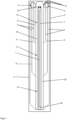
- the Figures 1 to 4 show schematic views of a first infrared module according to the invention.
- the infrared module can have a radiator 1 as an infrared source. This can be a twin tube radiator, i.e. a radiator with two parallel heating elements that are connected in series.
- the radiator 1 can preferably be a shortwave or carbon radiator.
- the spotlight 1 is arranged in a module housing 2 with a window 3.
- the module housing 2 can be constructed of metal sheets and a quartz window as the window 3.
- the window 3 is transparent for at least a wavelength range in the infrared wavelength spectrum and is preferably a quartz glass plate.
- the window 3 may have a rectangular shape with a long longitudinal axis and a short side in the transverse direction perpendicular thereto.
- the module housing 2 On the module housing 2 there is an inlet opening 4 for introducing a gas flow into the module housing 2 and a drain opening 5 for draining it away a gas stream from the module housing 2 is arranged. Inside the module housing 2, lines 6 are provided for guiding the gas flow from the inlet opening 4 to the outlet opening 5, the gas flow being directed over an internal surface 7 of the window 3.
- the infrared module has, according to the invention, a gas flow distribution device 8 inside the module housing 2.
- This gas flow dividing device 8 can be implemented by a plurality of partitions 9, with which the gas flow introduced through the inlet opening 4 into the module housing 2 is divided into several gas flows that initially run in parallel.
- the gas streams can initially be guided separately from one another through the partition walls 9 and can be directed from the partition walls 9 towards the internal surface 7 of the window 3, where the gas streams partially wash over the internal surface 7 of the window 3 inside the module housing 2.
- three sections 10, 12, 14 of the inner surface 7 of the window 3 are washed over transversely to a longitudinal direction of the window 3. No partitions are provided in the area of window 3.
- the gas streams can be directed to the outlet opening 5 via further partition walls 9, which can be arranged in mirror image to the partition walls 9 on the side of the inlet opening 4. There the gas streams combine again and are derived from the module housing 2.
- the partitions 9 on the side of the drain opening 5 serve to form a transverse flow that is as laminar as possible over the inner surface 7 of the window 3.
- the gas flow can also flow in the opposite way through the module housing 2, This means that the gas flow can also flow into the module housing 2 through the drain opening 5 and flow out of the module housing 2 through the inlet opening 4.
- the structure ensures that the divided gas flows parallel to one another wash over the internal surface 7 of the window 3 inside the module housing 2 in sections, thus achieving uniform cooling.
- the radiator 1 can be operated via electrical connections 16 and can be held in the module housing 2 of the infrared module via a fastening 18 opposite the electrical connections 16 and via the electrical connections 16.
- the infrared module can preferably also have a reflector 20 directly above the radiator 1 in order to improve the light output of the infrared module.
- the reflector 20 can have a gold coating or a quartz coating in order to achieve a higher reflectivity for the infrared radiation of the radiator 1.
- the reflector 20 and the radiator 1 can together with the inner surface 7 of the window 3 along the sections 10, 12, 14 are flushed with the gas flows and thereby cooled externally.
- openings 22 can be arranged in the reflector 20, which allow the gas flows to flow through.
- the radiator 1 can have a cladding tube 24 and a heating element 26 enclosed in the cladding tube 24.
- the heating element 26 can be made of a material suitable for IR emitters, such as carbon or a suitable metal alloy, and can be electrically contacted via the electrical connections 16.
- the electrical connections 16 are connected to an electrical connection 28 on the outside of the module housing 2.
- the electrical feedthrough through the module housing 2 can be sealed and pressure-tight.
- Pipes 30, 32 can be arranged on the module housing 2, which are connected to the inlet opening 4 and the drain opening 5 or delimit them.
- the gas flow can be introduced into the module housing 2 through the pipes 30, 32 and removed again from the module housing 2.
- the infrared module can have the window 3 in the form of a quartz glass plate, which is used to transmit the IR radiation into a process space (in the Figures 1 to 4 not shown, but see Figure 10 ) is suitable and intended.
- the infrared module can be sealed to the outside with the module housing 2 from a part of the environment, such as the process room, and preferably fulfill the necessary protection classes.
- the infrared module can be completely sealed from its surroundings except for the inlet opening 4 and the outlet opening 5 and can then be used analogously to the embodiment Figure 10 be arranged within the process space.
- Supply and exhaust air lines as well as energy supply are led out of the process space accordingly with the help of the pipes 30, 32 and with the help of electrical lines (not shown) which are connected to the electrical connection 28 on the outside of the module housing 2.
- the infrared module and the window 3 can be gas-cooled in sections (for example, air-cooled).
- the resulting homogeneous cooling of the module housing 2 and the window 3 takes place via gas flow management, which is implemented by the partitions 9 and the lines 6 inside the module housing 2.
- the cooling does not take place in the longitudinal direction of the radiator 1 and not in the longitudinal direction of the window 3 or the infrared module, but rather transversely.
- the infrared module is supplied with uniformly cool gas or uniformly cool air over its entire length.
- the window 3 is flushed with uniformly cool gas along its short axis (i.e.
- the gas flow can be distributed via the partition walls 9, which act as gas baffles for the lines 6.
- the optimal number of ventilation sections depends on the length of the infrared module and the desired coolant flow or cooling gas flow (depending on the permitted maximum temperature). An adjustment of cross sections and air volumes over the length of the radiator 1 and the window 3 is therefore possible.
- the infrared module is preferably equipped with pressure sensors (not shown) in order to detect leakage (eg a broken pane of the window 3). Break detectors (not shown) for the window 3 or pressure sensors (not shown) for measuring a pressure drop are also conceivable. With such sensors, the volume flow of the gas flow can also be controlled or a safety shutdown can be carried out.
- the infrared module can have a control and can be connected to a central control for the purpose of transmitting data from the sensors. In this way, a restriction of the available gas quantity and/or flow speed (volume) can also be achieved or another "intelligent" adjustment of the gas flow or gas flows can be carried out.
- the emitter 1 can also be designed as a UV emitter (see also the third exemplary embodiment Figure 9 ). It is then a UV module instead of an infrared module.
- the window 3 must then be transparent to UV radiation or to a wavelength range in the UV spectrum, which can be achieved, for example, by using a quartz glass window as the window 3.
- the reflector 20 should be suitable for reflecting UV light and all parts of the UV module that are directly irradiated with the UV light from the UV lamp should be resistant to the UV light.
- the single radiator 1 several radiators arranged parallel to one another can also be used.
- perforated plates can also be used as a gas flow dividing device, as in the second exemplary embodiment according to Figures 5 to 8 is shown.
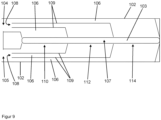
- the Figures 5 to 8 show schematic views of a second infrared module according to the invention.
- the infrared module can have a radiator 51 as an infrared source.
- the radiator 51 can preferably be a shortwave or carbon radiator.
- the radiator 51 is arranged in a module housing 52 with a window 53.
- the module housing 52 may be constructed of metal sheets and a quartz window as the window 53.
- the window is 53 transparent for at least a wavelength range in the infrared wavelength spectrum and is preferably a quartz glass plate.
- the window 53 may have a rectangular shape with a long longitudinal axis and a short transverse side perpendicular thereto. Analogous to the first exemplary embodiment, the window 53 extends below the radiator 51 in a longitudinal direction.
- An inlet opening 54 for introducing a gas stream into the module housing 52 and a drain opening 55 for discharging a gas stream from the module housing 52 are arranged on the module housing 52.
- lines 56 are provided inside the module housing 52 for guiding the gas flow from the inlet opening 54 to the outlet opening 55, the gas flow being directed over an internal surface 57 of the window 53.
- the infrared module has, according to the invention, a gas flow distribution device 58 in the form of at least one perforated plate inside the module housing 52.
- This gas flow dividing device 58 can be implemented by a plurality of perforated plates 58, 64 and partition walls 59, with which the gas flow introduced into the module housing 52 through the inlet opening 54 is divided into several gas flows that initially run in parallel.
- the gas streams can flow together again directly after the perforated plates 58, 64 and can flow from the partitions 59 and side openings (in the Figures 5 to 8 cannot be seen) are directed in the direction of the inner surface 57 of the window 53, where the gas streams wash over the inner surface 57 of the window 53 in sections next to each other in the interior of the module housing 52.
- many sections of the inner surface 57 of the window 53 are washed over transversely to the longitudinal direction of the window 53. No partitions are provided in the area of the window 53.
- the gas streams can be directed to the drain opening 55 via further partition walls 59 and perforated plates 58, 64, which can be arranged in mirror image to the partition walls 59 and the gas flow distribution device 58, 64 or the perforated plates 58, 64 on the side of the inlet opening 54. There the gas streams are again diverted from the module housing 52 in a uniform flow.
- the arrangement of the perforated plates 58, 64 and partitions 59 on the side of the drain opening serves to form a transverse flow that is as laminar as possible over the inner surface 57 of the window 53.
- the gas flow can also flow conversely through the module housing 52, that is to say that the gas flow can also flow into the module housing 52 through the drain opening 55 and can flow out of the module housing 52 through the inlet opening 54. Regardless of the connection, the structure ensures that the divided gas flows are parallel to each other on the inside Rinse the surface 57 of the window 53 inside the module housing 52 in sections and thus achieve uniform cooling.
- the radiator 51 can be operated via electrical connections 66 and can be held in the module housing 52 of the infrared module via a fastening 68 opposite the electrical connections 66 and via the electrical connections 66.
- the infrared module can preferably also have a reflector 70 directly above the radiator 51 in order to improve the light output of the infrared module.
- the reflector 70 can have a gold coating or a quartz coating in order to achieve a higher reflectivity for the infrared radiation of the radiator 51.
- the reflector 70 and the radiator 51, together with the inner surface 57 of the window 53, can be flushed with the gas flows generated by the gas flow distribution device 58, 64 or the perforated plates 58, 64 and partition walls 59 and thereby cooled externally.
- openings 72 can be arranged in the reflector 70, which allow the gas flows to flow through.
- the radiator 51 can have a cladding tube 74 and a heating element 76 enclosed in the cladding tube 74.
- the heating element 76 can be made of a material suitable for IR emitters, such as carbon or a suitable metal alloy or pure metals such as tungsten, and can be electrically heated via the electrical connections 66.
- the electrical connections 66 are connected to an electrical connection (not shown) on the outside of the module housing 52, but can also be electrically contacted along pipes for feeding and discharging the gas flow.
- the electrical feedthrough through the module housing 52 can be sealed and pressure-tight.
- the infrared module can have the window 53 in the form of a quartz glass plate, which is used to transmit the IR radiation into a process space (in the Figures 5 to 8 not shown, but see Figure 10 ) is suitable and intended.
- the infrared module can be sealed to the outside with the module housing 52 from a part of the environment, such as the process room, and thereby preferably fulfill the necessary protection classes.
- the infrared module can be completely sealed from its surroundings except for the inlet opening 54 and the drain opening 55 and can then be used analogously to the embodiment Figure 10 be arranged within the process space.
- Supply and exhaust air lines as well Energy supplies are accordingly led out of the process space with the help of the pipes and with the help of electrical lines (not shown).
- the infrared module and the window 53 can be gas-cooled in sections (for example, air-cooled).
- the resulting homogeneous cooling of the module housing 52 and the window 53 takes place via gas flow management, which is implemented through the perforated plates 58, 64, the partitions 59 and the lines 56 inside the module housing 52.
- the cooling does not take place in the longitudinal direction of the radiator 51 and not in the longitudinal direction of the window 53 or the infrared module, but rather transversely.
- the infrared module is supplied with uniformly cool gas or uniformly cool air over its entire length.
- the window 53 is flushed with uniformly cool gas along its short axis (i.e. transverse to the longitudinal axis of the window 53) and cooled evenly and efficiently.
- the gas flow can be distributed via the gas flow distribution device 58, 64. These force a uniformly strong and homogeneous gas flow along the sections of the window 53 of the infrared module, which runs perpendicular to the longitudinal direction of the window.
- the perforated plates 58 arranged at the front in the flow direction of the gas flow can have small holes 60, medium holes and large holes 62 or small holes 60 and large holes 62.
- the size of the holes 60, 61, 62 refers to the free cross section of the holes 60, 61, 62, which contributes to the essentially unhindered flow of gas.
- the size of the holes 60, 61, 62 preferably increases with increasing distance from the inlet opening 54 or from the outlet opening 55. This can ensure that the gas flows further away from the inlet opening 54 and the outlet opening 55 do not have a lower volume flow than the gas flows flowing closer to them.
- Holes 65 can also be arranged in the perforated plates 64 arranged behind them in the flow direction of the gas flow, which serve to further equalize the gas flows in the module housing 52.
- the optimal number of holes 60, 61, 62, 65 and perforated plates 58, 64 and the optimal arrangement of the partitions 59 depend on the length of the infrared module and the desired coolant flow or cooling gas flow (depending on the permitted maximum temperature). An adjustment of cross sections and air quantities over the length of the radiator 51 and the window 53 is therefore possible. There is preferably an overpressure in the infrared module. In the event of a leak, this prevents the penetration of flammable substances Gases into the module housing 52 to the radiator 51, where the flammable gas could otherwise ignite.
- the infrared module is preferably equipped with pressure sensors (not shown) to detect leakage (e.g. a broken pane of the window 53). Fracture detectors (not shown) for the window 53 or pressure sensors (not shown) for measuring a pressure drop are also conceivable. With such sensors, the volume flow of the gas flow can also be controlled or a safety shutdown can be carried out.
- the infrared module can have a control and can be connected to a central control for the purpose of transmitting data from the sensors. In this way, a restriction of the available gas quantity and/or flow speed (volume) can also be achieved or another "intelligent" adjustment of the gas flow or gas flows can be carried out.
- the emitter 51 can also be designed as at least one UV emitter. It is then a UV module instead of an infrared module.
- the window 53 must then be transparent to UV radiation or to a wavelength range in the UV spectrum, which can be achieved, for example, by using a quartz glass window as the window 53.
- the reflector 70 should be suitable for reflecting UV light and all parts of the UV module that are directly irradiated with the UV light from the UV lamps should be resistant to the UV light.
- the single radiator 1 several radiators arranged parallel to one another can also be used.
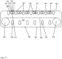
- Figure 9 shows a schematic structure of a third infrared module or UV module according to the invention.
- the infrared module or UV module can have at least one infrared emitter as an infrared source (for example ceramic emitters, carbon emitters or other IR emitters) or at least one UV emitter as a UV source (for example a UV LED array).
- the at least one infrared emitter or at least one UV emitter are in Figure 9 not visible but arranged above an elongated window 103 analogous to the previous two versions. They are arranged in a module housing 102 with the window 103.
- the window 103 is transparent for at least a wavelength range in the infrared wavelength spectrum and/or in the ultraviolet wavelength spectrum and is preferably a quartz glass plate.
- the window 103 may have a rectangular shape with rounded corners and with a long longitudinal axis and a short transverse side perpendicular thereto.
- An inlet opening 104 for introducing a gas flow into the module housing 102 and a drain opening 105 for discharging a gas flow from the module housing 102 are arranged on the module housing 102.
- lines 106 are provided inside the module housing 102 for directing the gas flow from the inlet opening 104 to the outlet opening 105, the gas flow being directed over an internal surface 107 of the window 103.
- the infrared module or UV module has, according to the invention, a gas flow distribution device 108 inside the module housing 102.
- This gas flow dividing device 108 can be implemented by a plurality of partitions 109, with which the gas flow introduced into the module housing 102 through the inlet opening 104 is divided into several gas flows that initially run in parallel.
- the gas streams can initially be guided separately from one another through the partition walls 109 and can be directed from the partition walls 109 towards the internal surface 107 of the window 103, where the gas streams partially wash over the internal surface 107 of the window 103 inside the module housing 102.
- three sections 110, 112, 114 of the inner surface 107 of the window 103 are washed across transversely to a longitudinal direction of the window 103.
- No partitions are provided in the area of the window 103.
- the gas streams can be directed to the outlet opening 105 via further partition walls 109, which can be arranged in mirror image to the partition walls 109 on the side of the inlet opening 104. There the gas streams combine again and are derived from the module housing 102.
- the partitions 109 on the side of the drain opening 105 serve to form a transverse flow that is as laminar as possible over the inner surface 107 of the window 103.
- the gas flow can also flow in the opposite way through the module housing 102, This means that the gas flow can also flow into the module housing 102 through the drain opening 105 and can flow out of the module housing 102 through the inlet opening 104. Regardless of the connection, the structure ensures that the divided gas flows parallel to one another wash over the internal surface 107 of the window 103 in sections inside the module housing 102 and thus uniform cooling is achieved.
- the infrared module or UV module can have the window 103 in the form of a quartz glass plate, which is used to transmit the IR radiation or UV radiation into a process space (in Figure 9 not shown, but see Figure 10 ) is suitable and intended.
- the infrared module or UV module can be sealed to the outside with the module housing 102 from part of the environment, such as the process room, and thereby preferably fulfill the necessary protection classes.
- the infrared module or UV module can be completely sealed from its surroundings except for the inlet opening 104 and the outlet opening 105 and can then be used analogously to the embodiment Figure 10 be arranged within the process space.
- the infrared module or UV module and the window 103 can be gas-cooled in sections (for example, air-cooled).
- the resulting homogeneous cooling of the module housing 102 and the window 103 takes place via gas flow management, which is implemented by the partitions 109 and the lines 106 inside the module housing 102.
- the cooling does not take place in the longitudinal direction of the infrared emitter or UV emitter and not in the longitudinal direction of the window 103 or the infrared module or UV module, but rather transversely. This means that the infrared module or UV module is supplied with uniformly cool gas or uniformly cool air over its entire length.
- the window 103 is flushed with uniformly cool gas along its short axis (i.e. transverse to the longitudinal axis of the window 103) and cooled evenly and efficiently.
- the gas flow can be distributed via the partitions 109, which act as gas baffles for the lines 106.
- These divide the module housing 102 of the infrared module into separate ventilation sections corresponding to sections 110, 112, 114. Three sections 110, 112, 114 do not have to be selected.
- the optimal number of ventilation sections depends on the length of the infrared module or UV module and the desired coolant flow or cooling gas flow (depending on the permitted maximum temperature).
- An adjustment of cross sections and air quantities over the length of the at least one infrared emitter or the at least one UV emitter and the window 103 is therefore possible.
- the infrared module or UV module is preferably equipped with pressure sensors (not shown) in order to detect leakage (e.g. a broken pane of the window 103). Fracture detectors (not shown) for the window 103 or pressure sensors (not shown) for measuring a pressure drop are also conceivable. With such sensors, the volume flow of the gas flow can also be controlled or a safety shutdown can be carried out.
- the infrared module or UV module can have a control and can be connected to a central control for the purpose of data transmission from the sensors. In this way, a restriction of the available gas quantity and/or flow speed (volume) can also be achieved or another "intelligent" adjustment of the gas flow or gas flows can be carried out.
- FIG 10 shows a schematic vertical cross-sectional view of a processing system according to the invention for changing a substance using infrared radiation or UV radiation containing six infrared modules or UV modules 150 according to the invention.
- the infrared modules or UV modules 150 are preferably according to one of the first three exemplary embodiments Figures 1 to 4 , 5 to 8 or 9 built up.
- Each infrared module or UV module 150 has at least one emitter 151, a module housing 152 with a gas flow dividing device (not seen) and with lines for guiding gas streams (not seen) over an internal surface 157 of a window 153, an inlet opening 154 and a drain opening 155.
- the structure and functionality of the infrared modules or UV modules 150 corresponds to the previous exemplary embodiments.
- the infrared modules or UV modules 150 are arranged between fans 160 in a system housing 162.
- the system housing encloses a process space 163.
- the infrared modules or UV modules 150 and the fans 160 are arranged within the system housing 162 in the process space 163.
- the interior of the infrared modules or UV modules 150 is sealed against the process space 163 with the module housing 152.
- the processing system can also have at least one device for applying a coating to be dried or hardened (the “slurry”). The coating is applied and dried in the processing system so that the end product on the winding roll is less sensitive to chemical and mechanical influences, or the rolled product does not stick or adhere to itself.
- Two holders 164, 166 are arranged in the process space 163, which can be designed as rollers, for example.
- the holders 164, 166 can also be arranged outside the process space 163.
- the holders 164, 166 hold a wire 168 or a band or a film as the material to be irradiated with the infrared modules or UV modules 150 in the process space 163.
- a wire mesh or a band can also be provided as a carrier on which the material to be irradiated is arranged or attached. With the help of the fans 160, the wire 168, the tape, the film or the carrier is stored in a floating manner.
- the fans 160 also act on the wire 168 or the band and keep it in suspension.
- the wire 168 or the band is preferably conveyed with the rollers in the process space 163 and dried and/or cured with the help of the blowers 160 and the infrared modules or UV modules 150.
- the processing system can therefore preferably be a drying system or a hardening system. The risk of ignition of gases generated when using the processing system Process room 163 is significantly reduced due to the uniform cooling with the infrared modules or UV modules 150.
Landscapes
- Engineering & Computer Science (AREA)
- Life Sciences & Earth Sciences (AREA)
- Microbiology (AREA)
- Mechanical Engineering (AREA)
- General Engineering & Computer Science (AREA)
- Chemical & Material Sciences (AREA)
- Combustion & Propulsion (AREA)
- Microelectronics & Electronic Packaging (AREA)
- Physics & Mathematics (AREA)
- Thermal Sciences (AREA)
- Physical Or Chemical Processes And Apparatus (AREA)
Applications Claiming Priority (1)
| Application Number | Priority Date | Filing Date | Title |
|---|---|---|---|
| CN202210369800.5A CN116940055A (zh) | 2022-04-08 | 2022-04-08 | 冷却的红外线或uv模块 |
Publications (1)
| Publication Number | Publication Date |
|---|---|
| EP4257904A1 true EP4257904A1 (fr) | 2023-10-11 |
Family
ID=81941076
Family Applications (1)
| Application Number | Title | Priority Date | Filing Date |
|---|---|---|---|
| EP22177057.1A Pending EP4257904A1 (fr) | 2022-04-08 | 2022-06-02 | Module infrarouge ou uv refroidi |
Country Status (2)
| Country | Link |
|---|---|
| EP (1) | EP4257904A1 (fr) |
| CN (1) | CN116940055A (fr) |
Citations (15)
| Publication number | Priority date | Publication date | Assignee | Title |
|---|---|---|---|---|
| US4494316A (en) * | 1983-03-14 | 1985-01-22 | Impact Systems, Inc. | Apparatus for drying a moving web |
| SE455709B (sv) * | 1987-06-05 | 1988-08-01 | Itronic Process Ab | Anordning for kylning av en vermebehandlingsanleggning, som er avsedd for banformigt alster |
| US5711089A (en) * | 1995-03-03 | 1998-01-27 | Hosokawa Bepex Corporation | Radiant heater for processing of polymers |
| JP2000162397A (ja) * | 1998-11-30 | 2000-06-16 | Iwasaki Electric Co Ltd | 紫外線硬化装置 |
| WO2008002904A2 (fr) * | 2006-06-26 | 2008-01-03 | Thermal Processing Solutions, Inc. | Four infrarouge à tapis pour cuisson thermique rapide doté d'une partie de chauffage de forte intensité |
| JP2009072700A (ja) * | 2007-09-20 | 2009-04-09 | Iwasaki Electric Co Ltd | 紫外線照射装置 |
| US20110163651A1 (en) * | 2008-06-16 | 2011-07-07 | Heraeus Noblelight Gmbh | Compact uv irradiation module |
| KR20120080421A (ko) * | 2011-01-07 | 2012-07-17 | 주식회사 딜리 | 적외선차단이 가능한 uv경화기 |
| US20120235060A1 (en) * | 2011-03-16 | 2012-09-20 | Iwasaki Electric Co., Ltd. | Ultraviolet irradiator and ultraviolet irradiating apparatus using the same |
| JP2013057438A (ja) | 2011-09-08 | 2013-03-28 | Toppan Printing Co Ltd | 塗膜の乾燥装置 |
| JP2016189394A (ja) * | 2015-03-30 | 2016-11-04 | ウシオ電機株式会社 | デスミア用エキシマ光照射装置およびデスミア処理方法 |
| EP3321574A1 (fr) * | 2016-11-14 | 2018-05-16 | Koninklijke Philips N.V. | Dispositif d'éclairage |
| WO2019154542A1 (fr) * | 2018-02-09 | 2019-08-15 | Heraeus Noblelight Gmbh | Module émetteur d'uv et utilisation dudit module |
| DE102018122910A1 (de) * | 2018-09-18 | 2020-03-19 | Heraeus Noblelight Gmbh | Infrarot-Erwärmungseinheit zum Trocknen von Tinten oder Lacken in einer Druckmaschine, sowie Infrarotstrahler-Modul für eine Druckmaschine |
| US10739069B2 (en) | 2016-03-28 | 2020-08-11 | Ngk Insulators, Ltd. | Low-temperature drying apparatus |
Family Cites Families (4)
| Publication number | Priority date | Publication date | Assignee | Title |
|---|---|---|---|---|
| CA3172541C (fr) * | 2009-06-05 | 2026-04-14 | Durr Systems, Inc. | Barre flottante infrarouge amelioree |
| DE102014104851B4 (de) * | 2014-04-04 | 2017-03-30 | Heraeus Noblelight Gmbh | Vorrichtung zur Entkeimung mittels ultravioletter Strahlung |
| CN109611238B (zh) * | 2018-12-24 | 2020-04-24 | 南京航空航天大学 | 一种肋片强化换热红外抑制器及红外抑制方法 |
| CN112393484A (zh) * | 2019-08-16 | 2021-02-23 | 鸿富锦精密工业(武汉)有限公司 | 气流罩 |
-
2022
- 2022-04-08 CN CN202210369800.5A patent/CN116940055A/zh active Pending
- 2022-06-02 EP EP22177057.1A patent/EP4257904A1/fr active Pending
Patent Citations (15)
| Publication number | Priority date | Publication date | Assignee | Title |
|---|---|---|---|---|
| US4494316A (en) * | 1983-03-14 | 1985-01-22 | Impact Systems, Inc. | Apparatus for drying a moving web |
| SE455709B (sv) * | 1987-06-05 | 1988-08-01 | Itronic Process Ab | Anordning for kylning av en vermebehandlingsanleggning, som er avsedd for banformigt alster |
| US5711089A (en) * | 1995-03-03 | 1998-01-27 | Hosokawa Bepex Corporation | Radiant heater for processing of polymers |
| JP2000162397A (ja) * | 1998-11-30 | 2000-06-16 | Iwasaki Electric Co Ltd | 紫外線硬化装置 |
| WO2008002904A2 (fr) * | 2006-06-26 | 2008-01-03 | Thermal Processing Solutions, Inc. | Four infrarouge à tapis pour cuisson thermique rapide doté d'une partie de chauffage de forte intensité |
| JP2009072700A (ja) * | 2007-09-20 | 2009-04-09 | Iwasaki Electric Co Ltd | 紫外線照射装置 |
| US20110163651A1 (en) * | 2008-06-16 | 2011-07-07 | Heraeus Noblelight Gmbh | Compact uv irradiation module |
| KR20120080421A (ko) * | 2011-01-07 | 2012-07-17 | 주식회사 딜리 | 적외선차단이 가능한 uv경화기 |
| US20120235060A1 (en) * | 2011-03-16 | 2012-09-20 | Iwasaki Electric Co., Ltd. | Ultraviolet irradiator and ultraviolet irradiating apparatus using the same |
| JP2013057438A (ja) | 2011-09-08 | 2013-03-28 | Toppan Printing Co Ltd | 塗膜の乾燥装置 |
| JP2016189394A (ja) * | 2015-03-30 | 2016-11-04 | ウシオ電機株式会社 | デスミア用エキシマ光照射装置およびデスミア処理方法 |
| US10739069B2 (en) | 2016-03-28 | 2020-08-11 | Ngk Insulators, Ltd. | Low-temperature drying apparatus |
| EP3321574A1 (fr) * | 2016-11-14 | 2018-05-16 | Koninklijke Philips N.V. | Dispositif d'éclairage |
| WO2019154542A1 (fr) * | 2018-02-09 | 2019-08-15 | Heraeus Noblelight Gmbh | Module émetteur d'uv et utilisation dudit module |
| DE102018122910A1 (de) * | 2018-09-18 | 2020-03-19 | Heraeus Noblelight Gmbh | Infrarot-Erwärmungseinheit zum Trocknen von Tinten oder Lacken in einer Druckmaschine, sowie Infrarotstrahler-Modul für eine Druckmaschine |
Also Published As
| Publication number | Publication date |
|---|---|
| CN116940055A (zh) | 2023-10-24 |
Similar Documents
| Publication | Publication Date | Title |
|---|---|---|
| EP1528388B1 (fr) | Diodes d'émission de lumière UV comme source de rayonnement d'un dispositif pour le vieillisement artificiel des échantillons | |
| EP1169611B1 (fr) | Appareil d'exposition a des rayons | |
| DE10125770C2 (de) | Bestrahlungsvorrichtung mit langgestreckter Strahlungsquelle und Verfahren zum Betrieb derselben | |
| EP2907527A1 (fr) | Procédé de fonctionnement pour un dispositif de rayonnement | |
| DE69836253T2 (de) | Doppelfensterabgasanlage für waferplasmabearbeitungsvorrichtung | |
| DE102015113766B4 (de) | Strahlermodul sowie Verwendung des Strahlermoduls | |
| EP0554538B1 (fr) | Procédé et dispositif pour chauffer une matière | |
| DE102016102187B3 (de) | Vorrichtung für die Behandlung eines Substrats mit UV-Strahlung und Verwendung der Vorrichtung | |
| EP4257904A1 (fr) | Module infrarouge ou uv refroidi | |
| EP3393679B1 (fr) | Dispositif de durcissement aux uv présentant des miroirs divisés de déviation des uv | |
| DE10163087B4 (de) | Infrarotstrahler zur thermischen Behandlung von Gütern | |
| EP3012858B1 (fr) | Système de chambre de traitement et procédé de rayonnement d'un substrat dans une chambre de traitement | |
| WO1998054525A1 (fr) | Dispositif pour l'exposition d'un substrat a des rayons uv et procede pour l'exploitation de ce dispositif | |
| WO2017008987A1 (fr) | Procédé pour faire fonctionner une lampe à excimère au xénon et système de lampe comprenant une lampe à excimère | |
| DE102019125606B3 (de) | Bestrahlungsvorrichtung zum Bestrahlen von Substraten mit UV-Strahlung sowie ein Verfahren zum Betrieb einer Bestrahlungsvorrichtung | |
| DE10156915A1 (de) | Vorrichtung zum homogenen Erwärmen von Substraten oder Oberflächen und dessen Verwendung | |
| DE102023104901B4 (de) | Vorrichtung und Verfahren zur UV-Strahlungsaktivierung von bahnförmigen Klebebändern | |
| DE102015106962A1 (de) | Bestrahlungsvorrichtung, Prozessieranordnung und Verfahren zum Betreiben einer Bestrahlungsvorrichtung | |
| WO2021180388A1 (fr) | Système de chauffage | |
| WO2019228773A1 (fr) | Ensemble guide d'ondes d'un système de soudage laser, système de soudage laser correspondant ainsi que procédé de soudage associé | |
| DE102024100757A1 (de) | Trocknungsvorrichtung | |
| EP3291651B1 (fr) | Dispositif et procédé de production d'un plasma atmosphérique | |
| DE102015212969B4 (de) | UV-Bestrahlungsvorrichtung | |
| EP0916398A1 (fr) | Dispositif de déclenchement et/ou promotion de processus chimiques par irradiation d'un réactant avec radiation électromagnétique | |
| EP2113309A1 (fr) | Dispositif de durcissement par rayonnement UV |
Legal Events
| Date | Code | Title | Description |
|---|---|---|---|
| PUAI | Public reference made under article 153(3) epc to a published international application that has entered the european phase |
Free format text: ORIGINAL CODE: 0009012 |
|
| STAA | Information on the status of an ep patent application or granted ep patent |
Free format text: STATUS: REQUEST FOR EXAMINATION WAS MADE |
|
| 17P | Request for examination filed |
Effective date: 20220602 |
|
| AK | Designated contracting states |
Kind code of ref document: A1 Designated state(s): AL AT BE BG CH CY CZ DE DK EE ES FI FR GB GR HR HU IE IS IT LI LT LU LV MC MK MT NL NO PL PT RO RS SE SI SK SM TR |
|
| STAA | Information on the status of an ep patent application or granted ep patent |
Free format text: STATUS: EXAMINATION IS IN PROGRESS |
|
| 17Q | First examination report despatched |
Effective date: 20250204 |