EP4257917B1 - Detektionsvorrichtung und polstückfertigungsanlage - Google Patents
Detektionsvorrichtung und polstückfertigungsanlage Download PDFInfo
- Publication number
- EP4257917B1 EP4257917B1 EP22888630.5A EP22888630A EP4257917B1 EP 4257917 B1 EP4257917 B1 EP 4257917B1 EP 22888630 A EP22888630 A EP 22888630A EP 4257917 B1 EP4257917 B1 EP 4257917B1
- Authority
- EP
- European Patent Office
- Prior art keywords
- pole piece
- laser ranging
- ranging sensor
- protective enclosure
- thickness
- Prior art date
- Legal status (The legal status is an assumption and is not a legal conclusion. Google has not performed a legal analysis and makes no representation as to the accuracy of the status listed.)
- Active
Links
Images


Classifications
-
- G—PHYSICS
- G01—MEASURING; TESTING
- G01B—MEASURING LENGTH, THICKNESS OR SIMILAR LINEAR DIMENSIONS; MEASURING ANGLES; MEASURING AREAS; MEASURING IRREGULARITIES OF SURFACES OR CONTOURS
- G01B11/00—Measuring arrangements characterised by the use of optical techniques
- G01B11/02—Measuring arrangements characterised by the use of optical techniques for measuring length, width or thickness
- G01B11/06—Measuring arrangements characterised by the use of optical techniques for measuring length, width or thickness for measuring thickness ; e.g. of sheet material
- G01B11/0616—Measuring arrangements characterised by the use of optical techniques for measuring length, width or thickness for measuring thickness ; e.g. of sheet material of coating
- G01B11/0625—Measuring arrangements characterised by the use of optical techniques for measuring length, width or thickness for measuring thickness ; e.g. of sheet material of coating with measurement of absorption or reflection
-
- B—PERFORMING OPERATIONS; TRANSPORTING
- B05—SPRAYING OR ATOMISING IN GENERAL; APPLYING FLUENT MATERIALS TO SURFACES, IN GENERAL
- B05C—APPARATUS FOR APPLYING FLUENT MATERIALS TO SURFACES, IN GENERAL
- B05C21/00—Accessories or implements for use in connection with applying liquids or other fluent materials to surfaces, not provided for in groups B05C1/00 - B05C19/00
-
- G—PHYSICS
- G01—MEASURING; TESTING
- G01B—MEASURING LENGTH, THICKNESS OR SIMILAR LINEAR DIMENSIONS; MEASURING ANGLES; MEASURING AREAS; MEASURING IRREGULARITIES OF SURFACES OR CONTOURS
- G01B11/00—Measuring arrangements characterised by the use of optical techniques
- G01B11/02—Measuring arrangements characterised by the use of optical techniques for measuring length, width or thickness
- G01B11/06—Measuring arrangements characterised by the use of optical techniques for measuring length, width or thickness for measuring thickness ; e.g. of sheet material
-
- G—PHYSICS
- G01—MEASURING; TESTING
- G01B—MEASURING LENGTH, THICKNESS OR SIMILAR LINEAR DIMENSIONS; MEASURING ANGLES; MEASURING AREAS; MEASURING IRREGULARITIES OF SURFACES OR CONTOURS
- G01B21/00—Measuring arrangements or details thereof, where the measuring technique is not covered by the other groups of this subclass, unspecified or not relevant
- G01B21/02—Measuring arrangements or details thereof, where the measuring technique is not covered by the other groups of this subclass, unspecified or not relevant for measuring length, width, or thickness
- G01B21/04—Measuring arrangements or details thereof, where the measuring technique is not covered by the other groups of this subclass, unspecified or not relevant for measuring length, width, or thickness by measuring coordinates of points
- G01B21/045—Correction of measurements
-
- G—PHYSICS
- G01—MEASURING; TESTING
- G01B—MEASURING LENGTH, THICKNESS OR SIMILAR LINEAR DIMENSIONS; MEASURING ANGLES; MEASURING AREAS; MEASURING IRREGULARITIES OF SURFACES OR CONTOURS
- G01B21/00—Measuring arrangements or details thereof, where the measuring technique is not covered by the other groups of this subclass, unspecified or not relevant
- G01B21/02—Measuring arrangements or details thereof, where the measuring technique is not covered by the other groups of this subclass, unspecified or not relevant for measuring length, width, or thickness
- G01B21/04—Measuring arrangements or details thereof, where the measuring technique is not covered by the other groups of this subclass, unspecified or not relevant for measuring length, width, or thickness by measuring coordinates of points
- G01B21/047—Accessories, e.g. for positioning, for tool-setting, for measuring probes
-
- G—PHYSICS
- G01—MEASURING; TESTING
- G01B—MEASURING LENGTH, THICKNESS OR SIMILAR LINEAR DIMENSIONS; MEASURING ANGLES; MEASURING AREAS; MEASURING IRREGULARITIES OF SURFACES OR CONTOURS
- G01B5/00—Measuring arrangements characterised by the use of mechanical techniques
- G01B5/0011—Arrangements for eliminating or compensation of measuring errors due to temperature or weight
- G01B5/0014—Arrangements for eliminating or compensation of measuring errors due to temperature or weight due to temperature
-
- G—PHYSICS
- G01—MEASURING; TESTING
- G01S—RADIO DIRECTION-FINDING; RADIO NAVIGATION; DETERMINING DISTANCE OR VELOCITY BY USE OF RADIO WAVES; LOCATING OR PRESENCE-DETECTING BY USE OF THE REFLECTION OR RERADIATION OF RADIO WAVES; ANALOGOUS ARRANGEMENTS USING OTHER WAVES
- G01S17/00—Systems using the reflection or reradiation of electromagnetic waves other than radio waves, e.g. lidar systems
- G01S17/02—Systems using the reflection of electromagnetic waves other than radio waves
- G01S17/06—Systems determining position data of a target
- G01S17/08—Systems determining position data of a target for measuring distance only
-
- G—PHYSICS
- G01—MEASURING; TESTING
- G01S—RADIO DIRECTION-FINDING; RADIO NAVIGATION; DETERMINING DISTANCE OR VELOCITY BY USE OF RADIO WAVES; LOCATING OR PRESENCE-DETECTING BY USE OF THE REFLECTION OR RERADIATION OF RADIO WAVES; ANALOGOUS ARRANGEMENTS USING OTHER WAVES
- G01S17/00—Systems using the reflection or reradiation of electromagnetic waves other than radio waves, e.g. lidar systems
- G01S17/88—Lidar systems specially adapted for specific applications
-
- G—PHYSICS
- G01—MEASURING; TESTING
- G01S—RADIO DIRECTION-FINDING; RADIO NAVIGATION; DETERMINING DISTANCE OR VELOCITY BY USE OF RADIO WAVES; LOCATING OR PRESENCE-DETECTING BY USE OF THE REFLECTION OR RERADIATION OF RADIO WAVES; ANALOGOUS ARRANGEMENTS USING OTHER WAVES
- G01S7/00—Details of systems according to groups G01S13/00, G01S15/00, G01S17/00
- G01S7/48—Details of systems according to groups G01S13/00, G01S15/00, G01S17/00 of systems according to group G01S17/00
- G01S7/481—Constructional features, e.g. arrangements of optical elements
- G01S7/4811—Constructional features, e.g. arrangements of optical elements common to transmitter and receiver
- G01S7/4813—Housing arrangements
-
- H—ELECTRICITY
- H01—ELECTRIC ELEMENTS
- H01M—PROCESSES OR MEANS, e.g. BATTERIES, FOR THE DIRECT CONVERSION OF CHEMICAL ENERGY INTO ELECTRICAL ENERGY
- H01M10/00—Secondary cells; Manufacture thereof
- H01M10/04—Construction or manufacture in general
-
- H—ELECTRICITY
- H01—ELECTRIC ELEMENTS
- H01M—PROCESSES OR MEANS, e.g. BATTERIES, FOR THE DIRECT CONVERSION OF CHEMICAL ENERGY INTO ELECTRICAL ENERGY
- H01M10/00—Secondary cells; Manufacture thereof
- H01M10/42—Methods or arrangements for servicing or maintenance of secondary cells or secondary half-cells
- H01M10/48—Accumulators combined with arrangements for measuring, testing or indicating the condition of cells, e.g. the level or density of the electrolyte
-
- B—PERFORMING OPERATIONS; TRANSPORTING
- B05—SPRAYING OR ATOMISING IN GENERAL; APPLYING FLUENT MATERIALS TO SURFACES, IN GENERAL
- B05C—APPARATUS FOR APPLYING FLUENT MATERIALS TO SURFACES, IN GENERAL
- B05C11/00—Component parts, details or accessories not specifically provided for in groups B05C1/00 - B05C9/00
- B05C11/10—Storage, supply or control of liquid or other fluent material; Recovery of excess liquid or other fluent material
- B05C11/1002—Means for controlling supply, i.e. flow or pressure, of liquid or other fluent material to the applying apparatus, e.g. valves
- B05C11/1005—Means for controlling supply, i.e. flow or pressure, of liquid or other fluent material to the applying apparatus, e.g. valves responsive to condition of liquid or other fluent material already applied to the surface, e.g. coating thickness, weight or pattern
-
- G—PHYSICS
- G01—MEASURING; TESTING
- G01B—MEASURING LENGTH, THICKNESS OR SIMILAR LINEAR DIMENSIONS; MEASURING ANGLES; MEASURING AREAS; MEASURING IRREGULARITIES OF SURFACES OR CONTOURS
- G01B2210/00—Aspects not specifically covered by any group under G01B, e.g. of wheel alignment, caliper-like sensors
- G01B2210/40—Caliper-like sensors
- G01B2210/44—Caliper-like sensors with detectors on both sides of the object to be measured
-
- Y—GENERAL TAGGING OF NEW TECHNOLOGICAL DEVELOPMENTS; GENERAL TAGGING OF CROSS-SECTIONAL TECHNOLOGIES SPANNING OVER SEVERAL SECTIONS OF THE IPC; TECHNICAL SUBJECTS COVERED BY FORMER USPC CROSS-REFERENCE ART COLLECTIONS [XRACs] AND DIGESTS
- Y02—TECHNOLOGIES OR APPLICATIONS FOR MITIGATION OR ADAPTATION AGAINST CLIMATE CHANGE
- Y02E—REDUCTION OF GREENHOUSE GAS [GHG] EMISSIONS, RELATED TO ENERGY GENERATION, TRANSMISSION OR DISTRIBUTION
- Y02E60/00—Enabling technologies; Technologies with a potential or indirect contribution to GHG emissions mitigation
- Y02E60/10—Energy storage using batteries
Definitions
- the present application relates to the technical field of battery manufacturing, and in particular, to a detection device as specified in any of claims 1-8 and pole piece manufacturing equipment as specified in any of claims 9-13.
- a detection device in a manufacturing process of a pole piece of a battery, a detection device will be used to detect the thickness of the pole piece, so as to ensure the forming quality of the pole piece of the battery.
- the temperature of the detection device will continue to rise. A too high temperature will cause the detection accuracy of the detection device to decrease, and may even damage the detection device.
- CN110518441A relates to a high-efficiency no-dead-angle heat sink for a laser device.
- US2009/046752A1 relates to a gas-cooled laser device.
- CN211375052U relates to laser distance measuring device suitable for harsh environments.
- CN208795842U describes pole piece coating thickness laser online measuring device.
- CN106019295 describes laser thickness measuring and distance measuring device and real-time correction method thereof.
- DE102012224251 describes method for monitoring thickness of active material applied on substrate, utilized for manufacturing electrodes for lithium-ion-battery cells.
- CN102519372 describes laser thickness measuring apparatus of lithium battery electrode and working method thereof.
- CN2788125 describes on-line monitoring device for measuring thickness of smooth surface plate.
- An objective of embodiments of the present application is to provide a detection device as specified in any of claims 1-8, which can effectively cool a laser ranging sensor, so as to improve the detection accuracy and use safety of the laser ranging sensor.
- Another objective of the embodiments of the present application is to provide pole piece manufacturing equipment including the above detection device.
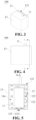
- the embodiments of the present application provide a detection device as specified in any of claims 1-8, including: a laser ranging sensor; and a cooling module, which includes a first protective enclosure and a cooling plate, where the first protective enclosure encloses the outside of the laser ranging sensor; the first protective enclosure is provided with an avoidance portion for avoiding a laser light path of the laser ranging sensor; the first protective enclosure has a first opening; the cooling plate covers the first opening; an air flow channel is defined inside the cooling plate; surfaces of the cooling plate are provided with air inlet holes and first air outlet holes which are communicated with the air flow channel; and the first air outlet holes are disposed in a manner of facing the laser ranging sensor to blow air to the laser ranging sensor to cool the laser ranging sensor; wherein a side of the cooling plate facing the laser ranging sensor is provided with a position-limit slot, and part of the laser ranging sensor is embedded in the position-limit slot and is fixedly connected with the cooling plate; and there is a first space between the laser ranging sensor
- the detection device includes the laser ranging sensor and the cooling module.
- the cooling module includes the first protective enclosure and the cooling plate; the first protective enclosure encloses the outside of the laser ranging sensor; the first protective enclosure has the first opening; the cooling plate covers the first opening, so that the laser ranging sensor is located between the first protective enclosure and the cooling plate.
- the air flow channel is defined inside the cooling plate, and the surface of the cooling plate is provided with the air inlet holes and the first air outlet holes which are communicated with the air flow channel; and the first air outlet holes are disposed in a manner of facing the laser ranging sensor.
- the compressed air when compressed air is introduced into the air inlet holes, the compressed air can be blown from the air outlet holes to the laser ranging sensor after passing through the air flow channel.
- the compressed air achieves the purpose of cooling the laser ranging sensor.
- it helps to improve the detection accuracy of the laser ranging sensor, and prolongs the service life of the laser ranging sensor.
- the cooling plate includes a first surface and a second surface which are disposed adjacently; the first surface is disposed in a manner of facing the laser ranging sensor; the first air outlet holes are formed in the first surface; and the air inlet holes are formed in the second surface.
- the first surface and the second surface of the cooling plate are arranged adjacently, and the first surface faces the laser ranging sensor; the first air outlet holes and the air inlet holes are respectively formed in the first surface and the second surface. That is, the second surface can be any one of four surfaces adjacent to the first surface. That is, the air inlet holes are formed in any one of the four surfaces adjacent to the first surface.
- the number of the air flow channel is increased, thereby increasing a flow area of the compressed air in the cooling plate, which in turn helps to improve the cooling effect on the laser ranging sensor.
- each of the air flow channels has multiple first air outlet holes arranged at intervals along an extending direction of the air flow channel.
- the volume of the compressed air blown to the laser ranging sensor at the same time can be increased, so as to effectively improve the heat exchange efficiency with hot air surrounding the laser ranging sensor, which can in turn improve the cooling effect on the laser ranging sensor.
- the position-limit slot by means of arranging the position-limit slot on the side of the cooling plate facing the laser ranging sensor, art of the laser ranging sensor is embedded in the position-limit slot and is fixedly connected with the cooling plate, the position-limit slot has a limiting effect on the laser ranging sensor, which prevents a relative movement of the laser ranging sensor from the cooling plate, improves the reliability of assembling of the laser ranging sensor and the cooling plate, and helps to improve the detection accuracy of the laser ranging sensor.
- the compressed air can be blown out from the first space while it is blown out from the first air outlet holes to the laser ranging sensor, which ensures the smoothness of air flowing, and in turn ensures that the compressed air can be continuously blown out from the first air outlet holes to continuously cool the laser ranging sensor.
- the first air outlet holes on the two side walls of two sides of the position-limit slot can synchronously blow air to side surfaces of the laser ranging sensor, so as to further improve the cooling efficiency for the laser ranging sensor.
- the first protective enclosure is provided with a second opening, and the second opening is configured for connecting the laser ranging sensor with external equipment.
- a connecting end of a laser emitting end of the laser ranging sensor is connected to the external equipment (such as a power supply device or a power supply cable), which ensures the normal use of the laser ranging sensor.
- the first protective enclosure is provided with an air outlet.
- the first protective enclosure is provided with the air outlet.
- the compressed air in the cooling plate exchanges heat with the hot air surrounding the laser ranging sensor
- the compressed air can be quickly discharged out of the first protective enclosure from the air outlet, so as to ensure that the compressed air cyclically cools the laser ranging sensor in the first protective enclosure, thereby helping to further improve the cooling efficiency of the laser ranging sensor.
- the position of the laser emitting end of the laser ranging sensor corresponds to the position of the air outlet, and the laser emitting end of the laser ranging sensor can emit laser light out of the first protective enclosure from the air outlet, thereby achieving ranging on an object to be detected.
- a second space for air to flow is formed between the inner wall surface of the first protective enclosure and the laser ranging sensor.
- the number of the second air outlet hole is increased, and the volume of air blown to the second protective enclosure is increased, thereby helping to improve the cooling effect on the cooling module and further improving the cooling efficiency of the laser ranging sensor.
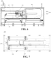
- the embodiments of the present application provide pole piece manufacturing equipment, including: a coating device configured for coating a surface of a pole piece; the detection device according to any one of the embodiments of the first aspect, where the number of the detection devices is two, and the two detection devices are respectively arranged on two sides of the pole piece along the thickness direction and are configured for detecting the thickness of the pole piece; and a controller, which is configured for receiving the thickness of the pole piece detected by the detection devices and controlling, according to a comparison result between the thickness of the pole piece and a preset thickness threshold, the coating device to adjust the thickness of the pole piece.
- the pole piece manufacturing equipment includes the coating device, the controller, and the detection devices according to any one of the embodiments of the first aspect.
- the coating device is configured for coating the surface of the pole piece.
- the detection devices are arranged on the two sides of the pole piece along the thickness direction to detect the thickness of the pole piece.
- the controller (such as an industrial personal computer) is electrically connected with the detection devices and the coating device, and is configured for receiving the thickness of the pole piece detected by the detection devices, comparing the thickness of the pole piece with the preset thickness threshold, and controlling, according to the comparison result, the coating device to adjust the thickness of the pole piece, so that the thickness of the pole piece reaches the preset threshold, which ensures the consistency in the thickness of the pole piece and improves the performance of a battery.
- the thickness of the pole piece includes a thickness of a thinned region of the pole piece.
- the pole piece manufacturing equipment further includes the oven drying device and the rolling device.
- the oven drying device is arranged downstream of the coating device, and is configured for oven-drying the pole piece after the coating device is used to coat the pole piece.
- the rolling device is arranged downstream of the oven drying device, and is configured for rolling the pole piece after the oven drying device dries the pole piece.
- the thickness of the pole piece rolled by the rolling device is a real-time thickness of the pole piece in an offline coating process; the thickness of the pole piece during the coating cannot be adjusted in real time; and there is a risk of batch scrapping of pole pieces due to overspecification caused by lagging detection of the thickness of the pole piece.
- the pole piece manufacturing equipment further includes: a base; a scanning frame, which is arranged on the base and slidably connected with the base, where the detection devices are arranged on the scanning frame; a magnetoscale assembly, which includes a magnetoscale arranged on the base and a magnetoscale reading head arranged on the scanning frame, and the magnetoscale reading head is configured for reading, when the scanning frame slides relative to the base, equally spaced magnetic waves pre-recorded on the magnetoscale, so as to detect a linear displacement of the scanning frame.
- the pole piece manufacturing equipment further includes a first check piece and a second check piece; the first check piece and the second check piece are arranged on the base and are respectively located on two sides of the pole piece in the width direction; one of the first check piece and the second check piece is configured for compensating the temperature of the pole piece, and the other one is configured for calibrating the temperature after compensation.
- the first check piece and the second check piece connected with the first check piece by a half-bridge are arranged on the base, and the first check piece and the second check piece are respectively located on the two sides of the pole piece in the width direction; one of the first check piece and the second check piece can compensate the temperature of the pole piece after the air check and comparison, and the other one can calibrate the temperature after compensation, thereby avoiding the impact of the temperature on the detection of the thickness of the pole piece, which helps to improve the accuracy of detection of the thickness of the pole piece.
- the thickness of the pole piece of the electrode assembly There are many methods to detect the thickness of the pole piece of the electrode assembly, such as a micrometer measurement method and a laser measurement method. Due to manual measurement, the micrometer measurement method has a large measurement error. The laser measurement method can realize automatic detection of the thickness of the pole piece of the electrode assembly, and has high measurement accuracy, so this method is widely used in an automatic production line of battery manufacturing.
- the inventors have found that when the laser measurement method is used, since an infrared light sensitive element in a laser ranging sensor will expand or contract due to the impact of an ambient temperature, a corresponding range will be increased or decreased, so the detection accuracy of the laser ranging sensor is greatly affected by the ambient temperature. Particularly, when a working environment where the laser ranging sensor has a high temperature, and the laser ranging sensor is used for continuous detection, the temperature of an electrical measurement element in the laser sensor will continue to rise, thus leading to a decrease in the detection accuracy of the laser ranging sensor and even causing damage to the laser ranging sensor.
- the cooling plate 12 has air inlet holes 121, an air flow channel 123 and air outlet holes.
- the air flow channel 123 is communicated with the air inlet holes 121 and the air outlet holes. Since the air outlet holes are disposed in a manner of facing the laser ranging sensor 11, when compressed air is introduced into the air inlet holes 121, the compressed air is blown to the laser ranging sensor 11 through the air flow channel 123 and the air outlet holes, thereby exchanging heat to the laser ranging sensor 11 and then achieving a cooling effect on the laser ranging sensor 11.
- the first protective enclosure 13 can be a heat shield.
- the compressed air can form a vortex effect when flowing in the first protective enclosure 13 to cool all surfaces of the laser ranging sensor 11.
- external hot air can be prevented from entering the first protective enclosure 13.
- the first protective enclosure 13 encloses the outside of the laser ranging sensor 11, and the cooling plate 12 covers the first opening 131 of the first protective enclosure 13, so that the laser ranging sensor 11 is located between the first protective enclosure 13 and the cooling plate 12.
- the air flow channel 123 is defined inside the cooling plate 12, and surfaces of the cooling plate 12 are provided with the air inlet holes 121 and the first air outlet holes 122 which are communicated with the air flow channel 123; and the first air outlet holes 122 are disposed in a manner of facing the laser ranging sensor 11. In this way, when the compressed air is introduced into the air inlet holes 121, the compressed air can be blown from the air outlet holes to the laser ranging sensor 11 after passing through the air flow channel 123.
- the compressed air achieves the purpose of cooling the laser ranging sensor 11.
- it helps to improve the detection accuracy of the laser ranging sensor 11, and prolongs the service life of the laser ranging sensor 11.
- the cooling plate 12 includes a first surface and a second surface which are disposed adjacently.
- the first surface is disposed in a manner of facing the laser ranging sensor 11.
- the first air outlet holes 122 are formed in the first surface; and the air inlet holes 121 are formed in the second surface.
- the first surface and the second surface of the cooling plate 12 are arranged adjacently, and the first surface faces the laser ranging sensor 11.
- the first air outlet holes 122 and the air inlet holes 121 are respectively formed in the first surface and the second surface. That is, the second surface can be any one of four surfaces adjacent to the first surface. That is, the air inlet holes 121 are formed in any one of the four surfaces adjacent to the first surface.
- an extension length of the air flow channel 123 can be appropriately increased, which helps to improve the cooling effect of the compressed air on the cooling plate itself and in turn contributes to the cooling effect on the laser ranging sensor.
- the multiple air flow channels 123 there are multiple air flow channels 123.
- the multiple air flow channels 123 are arranged at intervals inside the cooling plate 12.
- the air flow channel 123 is a passage for air to circulate in the cooling plate 12.
- the number of the air flow channel 123 is increased, thereby increasing a flow area of the compressed air in the cooling plate 12, which in turn helps to improve the cooling effect on the laser ranging sensor 11.
- the multiple air inlet holes 121 are arranged at intervals on the second surface and are communicated with the multiple air flow channels 123 in a one-to-one correspondence manner.
- each of the air flow channels 123 has multiple first air outlet holes 122 arranged at intervals along an extending direction of the air flow channel 123.
- the air inlet holes 121 are formed in the second surface of the cooling plate 12, and one end of the air flow channel 123 is communicated with the air inlet holes 121, that is, the air flow channel 123 extends away from the second surface.
- the volume of the compressed air blown to the laser ranging sensor 11 at the same time can be increased, so as to effectively improve the heat exchange efficiency with hot air surrounding the laser ranging sensor 11, which can in turn improve the cooling effect on the laser ranging sensor 11.
- a side of the cooling plate 12 facing the laser ranging sensor 11 is provided with a position-limit slot 124, and part of the laser ranging sensor 11 is embedded in the position-limit slot 124 and is fixedly connected with the cooling plate 12.
- the position-limit slot 124 is a slot formed by the first surface of the cooling plate 12 that is partially recessed, and is configured for fixing the laser ranging sensor 11.
- the first space 111 is a space for air to flow between the first protective enclosure and the laser ranging sensor.
- the compressed air can be blown out from the first space 111 while it is blown out from the first air outlet holes 122 to the laser ranging sensor 11, which ensures the smoothness of air flowing, and in turn ensures that the compressed air can be continuously blown out from the first air outlet holes 122 to continuously cool the laser ranging sensor 11.
- the first standard thickness and the second standard thickness may be the same or different, which is not limited in this embodiment of the present application.
- the first check piece 206 and the second check piece 207 can be made of stainless steel, tungsten steel and other materials that are less affected by the environment, so as to avoid the impact of environmental factors such as humidity on the temperature compensation of the detection devices 100.
Landscapes
- Physics & Mathematics (AREA)
- Engineering & Computer Science (AREA)
- General Physics & Mathematics (AREA)
- Computer Networks & Wireless Communication (AREA)
- Radar, Positioning & Navigation (AREA)
- Remote Sensing (AREA)
- Electromagnetism (AREA)
- Chemical & Material Sciences (AREA)
- Manufacturing & Machinery (AREA)
- Chemical Kinetics & Catalysis (AREA)
- Electrochemistry (AREA)
- General Chemical & Material Sciences (AREA)
- Length Measuring Devices By Optical Means (AREA)
- Battery Electrode And Active Subsutance (AREA)
- Sealing Battery Cases Or Jackets (AREA)
- Secondary Cells (AREA)
Claims (13)
- Detektionsvorrichtung (100), die Folgendes umfasst:einen Laserentfernungsmesssensor (11); undein Kühlmodul, das ein erstes Schutzgehäuse (13) und eine Kühlplatte (12) umfasst, wobei das erste Schutzgehäuse (13) die Außenseite des Laserentfernungsmesssensors (11) umschließt; das erste Schutzgehäuse (13) mit einem Vermeidungsabschnitt (135) zum Vermeiden eines Laserlichtwegs des Laserentfernungsmesssensors (11) versehen ist; das erste Schutzgehäuse (13) eine erste Öffnung (131) aufweist; die Kühlplatte (12) die erste Öffnung (131) abdeckt; innerhalb der Kühlplatte (12) ein Luftstromkanal (123) definiert ist; Oberflächen der Kühlplatte (12) mit Lufteinlasslöchern (121) und ersten Luftauslasslöchern (122) versehen sind, die mit dem Luftstromkanal (123) in Verbindung gebracht sind; und die ersten Luftauslasslöcher (122) so positioniert sind, dass sie dem Laserentfernungsmesssensor (11) zugewandt sind, um Luft zu dem Laserentfernungsmesssensor (11) hin zu blasen, um den Laserentfernungsmesssensor (11) zu kühlen;dadurch gekennzeichnet, dass eine dem Laserentfernungsmesssensor (11) zugewandte Seite der Kühlplatte (12) mit einem Positionsbegrenzungsschlitz (124) versehen ist und ein Teil des Laserentfernungsmesssensors (11) in dem Positionsbegrenzungsschlitz (124) eingebettet und fest mit der Kühlplatte (12) verbunden ist; und wobei zwischen dem Laserentfernungsmesssensor (11) und der Bodenwand des Positionsbegrenzungsschlitzes (124) ein erster Raum (111) ist und zwei Seitenwände des Positionsbegrenzungsschlitzes (124) mit den ersten Luftauslasslöchern (122) versehen sind.
- Detektionsvorrichtung (100) nach Anspruch 1, wobei die Kühlplatte (12) eine erste Oberfläche und eine zweite Oberfläche umfasst, die benachbart positioniert sind; die erste Oberfläche so positioniert ist, dass sie dem Laserentfernungsmesssensor (11) zugewandt ist; die ersten Luftauslasslöcher (122) in der ersten Oberfläche gebildet sind; und die Lufteinlasslöcher (121) in der zweiten Oberfläche gebildet sind.
- Detektionsvorrichtung (100) nach Anspruch 1 oder 2, wobei mehrere Luftstromkanäle (123) vorhanden sind, die in Abständen innerhalb der Kühlplatte (12) angeordnet sind.
- Detektionsvorrichtung (100) nach einem der Ansprüche 1 bis 3, wobei jeder der Luftstromkanäle (123) mehrere erste Luftauslasslöcher (122) aufweist, die in Abständen entlang einer Erstreckungsrichtung des Luftstromkanals (123) angeordnet sind.
- Detektionsvorrichtung (100) nach einem der Ansprüche 1 bis 4, wobei das erste Schutzgehäuse (13) mit einer zweiten Öffnung (132) versehen ist und die zweite Öffnung (132) zum Verbinden des Laserentfernungsmesssensors (11) mit externen Geräten ausgelegt ist.
- Detektionsvorrichtung (100) nach einem der Ansprüche 1 bis 5, wobei das erste Schutzgehäuse (13) mit einem Luftauslass (133) versehen ist.
- Detektionsvorrichtung (100) nach einem der Ansprüche 1 bis 6, wobei zwischen der Innenwandoberfläche des ersten Schutzgehäuses (13) und dem Laserentfernungsmesssensor (11) ein zweiter Raum (134) für Luftströmungen gebildet ist.
- Detektionsvorrichtung (100) nach einem der Ansprüche 1 bis 7, wobei die Detektionsvorrichtung (100) ferner Folgendes umfasst: ein zweites Schutzgehäuse, das die Außenseite des Laserentfernungsmesssensors (11) und das Kühlmodul umschließt;
die von dem Laserentfernungsmesssensor (11) abgewandte Seite der Kühlplatte (12) mit zweiten Luftauslasslöchern versehen ist; die zweiten Luftauslasslöcher mit dem Luftstromkanal (123) in Verbindung gebracht sind und zwischen der Innenwandoberfläche des zweiten Schutzgehäuses und dem Kühlmodul ein dritter Raum für Luftströmungen gebildet ist. - Polstückfertigungsanlage (200), die Folgendes umfasst:eine Beschichtungsvorrichtung, die zum Beschichten einer Oberfläche eines Polstücks (300) ausgelegt ist;die Detektionsvorrichtung (100) nach einem der Ansprüche 1 bis 8, wobei zwei der Detektionsvorrichtungen (100) vorhanden sind und die zwei Detektionsvorrichtungen (100) jeweils auf zwei Seiten des Polstücks (300) entlang der Dickenrichtung angeordnet und zum Detektieren der Dicke des Polstücks (300) ausgelegt sind; undeine Steuereinheit (205), die zum Empfangen der Dicke des durch die Detektionsvorrichtungen (100) detektierten Polstücks (300) und Steuern, in Abhängigkeit von einem Ergebnis eines Vergleichs zwischen der Dicke des Polstücks (300) und einem voreingestellten Dickeschwellenwert ausgelegt ist, wobei die Beschichtungsvorrichtung zum Anpassen der Dicke des Polstücks (300) dient.
- Polstückfertigungsanlage (200) nach Anspruch 9, wobei die Dicke des Polstücks (300) eine Dicke eines dünner gemachten Bereichs des Polstücks (300) umfasst.
- Polstückfertigungsanlage (200) nach Anspruch 9 oder 10, wobei die Polstückfertigungsanlage (200) ferner Folgendes umfasst:eine Ofentrocknungsvorrichtung, die stromabwärts der Beschichtungsvorrichtung angeordnet und zum Ofentrocknen des Polstücks (300) ausgelegt ist; undeine Walzvorrichtung (203), die stromabwärts der Ofentrocknungsvorrichtung angeordnet und zum Walzen des Polstücks (300) ausgelegt ist;wobei die Detektionsvorrichtungen (100) stromaufwärts der Walzvorrichtung (203) angeordnet sind.
- Polstückfertigungsanlage (200) nach einem der Ansprüche 9 bis 11, wobei die Polstückfertigungsanlage (200) ferner Folgendes umfasst:eine Basis (201);einen Abtastungsrahmen (202), der auf der Basis (201) angeordnet und gleitfähig mit der Basis (201) verbunden ist, wobei die Detektionsvorrichtungen (100) auf dem Abtastungsrahmen (202) angeordnet sind; undeine Magnetskalabaugruppe (204), die eine auf der Basis (201) angeordnete Magnetskala (2041) und einen auf dem Abtastungsrahmen (202) angeordneten Magnetskalalesekopf (2042) umfasst, wobei der Magnetskalalesekopf (2042) zum Lesen, wenn der Abtastungsrahmen (202) relativ zu der Basis (201) gleitet, ausgelegt ist, wobei gleich beabstandete magnetische Wellen auf der Magnetskala (2041) vorher aufgezeichnet werden, um eine lineare Verschiebung des Abtastungsrahmens (202) zu detektieren.
- Polstückfertigungsanlage (200) nach einem der Ansprüche 9 bis 12, wobei die Polstückfertigungsanlage (200) ferner ein erstes Prüfstück (206) und ein zweites Prüfstück (207) umfasst; das erste Prüfstück (206) und das zweite Prüfstück (207) auf der Basis (201) angeordnet sind und sich jeweils auf zwei Seiten des Polstücks (300) in der Breitenrichtung befinden; eines von dem ersten Prüfstück (206) und dem zweiten Prüfstück (207) zum Kompensieren der Temperatur des Polstücks (300) ausgelegt ist und das andere zum Kalibrieren der Temperatur nach der Kompensation ausgelegt ist.
Priority Applications (1)
| Application Number | Priority Date | Filing Date | Title |
|---|---|---|---|
| EP25175325.7A EP4574275A3 (de) | 2022-02-17 | 2022-03-22 | Detektionsvorrichtung und vorrichtung zur herstellung einer elektrodenfolie |
Applications Claiming Priority (2)
| Application Number | Priority Date | Filing Date | Title |
|---|---|---|---|
| CN202220322938.5U CN216385506U (zh) | 2022-02-17 | 2022-02-17 | 检测装置及极片制造设备 |
| PCT/CN2022/082166 WO2023155265A1 (zh) | 2022-02-17 | 2022-03-22 | 检测装置及极片制造设备 |
Related Child Applications (2)
| Application Number | Title | Priority Date | Filing Date |
|---|---|---|---|
| EP25175325.7A Division-Into EP4574275A3 (de) | 2022-02-17 | 2022-03-22 | Detektionsvorrichtung und vorrichtung zur herstellung einer elektrodenfolie |
| EP25175325.7A Division EP4574275A3 (de) | 2022-02-17 | 2022-03-22 | Detektionsvorrichtung und vorrichtung zur herstellung einer elektrodenfolie |
Publications (3)
| Publication Number | Publication Date |
|---|---|
| EP4257917A1 EP4257917A1 (de) | 2023-10-11 |
| EP4257917A4 EP4257917A4 (de) | 2024-05-29 |
| EP4257917B1 true EP4257917B1 (de) | 2025-07-02 |
Family
ID=81238086
Family Applications (2)
| Application Number | Title | Priority Date | Filing Date |
|---|---|---|---|
| EP25175325.7A Pending EP4574275A3 (de) | 2022-02-17 | 2022-03-22 | Detektionsvorrichtung und vorrichtung zur herstellung einer elektrodenfolie |
| EP22888630.5A Active EP4257917B1 (de) | 2022-02-17 | 2022-03-22 | Detektionsvorrichtung und polstückfertigungsanlage |
Family Applications Before (1)
| Application Number | Title | Priority Date | Filing Date |
|---|---|---|---|
| EP25175325.7A Pending EP4574275A3 (de) | 2022-02-17 | 2022-03-22 | Detektionsvorrichtung und vorrichtung zur herstellung einer elektrodenfolie |
Country Status (6)
| Country | Link |
|---|---|
| US (1) | US11988498B2 (de) |
| EP (2) | EP4574275A3 (de) |
| CN (1) | CN216385506U (de) |
| ES (1) | ES3041659T3 (de) |
| HU (1) | HUE072873T2 (de) |
| WO (1) | WO2023155265A1 (de) |
Families Citing this family (6)
| Publication number | Priority date | Publication date | Assignee | Title |
|---|---|---|---|---|
| CN117564169A (zh) * | 2023-10-26 | 2024-02-20 | 合肥国轩电池科技有限公司 | 一种电池极片压花装置及方法 |
| CN118274727B (zh) * | 2024-04-30 | 2024-09-06 | 江苏远航锦锂新能源科技有限公司 | 一种辊压在线测厚装置及其测厚方法 |
| CN118566268B (zh) * | 2024-08-02 | 2024-11-08 | 玻尔兹曼(广州)科技有限公司 | 电池极片涂布生产线用克重检测调控装置 |
| CN119197427B (zh) * | 2024-11-28 | 2025-05-16 | 宁德时代新能源科技股份有限公司 | 测量装置、测量方法及电池生产设备 |
| CN119984060B (zh) * | 2025-02-13 | 2025-08-05 | 苏州毕格机械科技有限公司 | 一种电视背面板生产用厚度检测装置 |
| CN119958435B (zh) * | 2025-04-11 | 2025-06-20 | 浙江东柔新材料有限公司 | 保护膜检测系统及检测方法 |
Family Cites Families (21)
| Publication number | Priority date | Publication date | Assignee | Title |
|---|---|---|---|---|
| CN2788125Y (zh) * | 2005-04-13 | 2006-06-14 | 嘉兴学院 | 一种用于测量光洁面板材厚度的在线监测装置 |
| EP2003744B1 (de) * | 2007-06-14 | 2009-08-05 | Trumpf Laser Marking Systems AG | Gasgekühltes Lasergerät für hochkompakte Laserstrahlquellen |
| CN102519372A (zh) * | 2011-12-23 | 2012-06-27 | 常州工学院 | 锂电池电极的激光测厚装置及其工作方法 |
| TWI582837B (zh) * | 2012-06-11 | 2017-05-11 | 應用材料股份有限公司 | 在脈衝式雷射退火中使用紅外線干涉技術之熔化深度測定 |
| DE102012224251A1 (de) * | 2012-12-21 | 2014-06-26 | Robert Bosch Gmbh | Verfahren und Vorrichtung zur Überwachung der Dicke einer mit einem Nassbeschichtungsverfahren auf einem Substrat aufgebrachten Schicht |
| JP2016080629A (ja) * | 2014-10-21 | 2016-05-16 | 東京瓦斯株式会社 | ガス漏洩検知装置 |
| CN105403142A (zh) * | 2015-11-25 | 2016-03-16 | 华中科技大学 | 一种基于磁栅尺的便携平整度测量仪 |
| CN106019295A (zh) * | 2016-07-22 | 2016-10-12 | 沈阳美迪特信息技术有限公司 | 一种激光测厚、测距装置及其实时校正方法 |
| US11029713B2 (en) * | 2017-11-27 | 2021-06-08 | Liberty Reach Inc. | Method and system for expanding the range of working environments in which a 3-D or depth sensor can operate without damaging or degrading the measurement performance of the sensor |
| WO2019137343A1 (zh) * | 2018-01-09 | 2019-07-18 | 北京康斯特仪表科技股份有限公司 | 导流散热型干体温度校验仪 |
| CN208795842U (zh) * | 2018-09-30 | 2019-04-26 | 广州中国科学院沈阳自动化研究所分所 | 极片涂层厚度激光在线检测装置 |
| WO2020220005A1 (en) * | 2019-04-26 | 2020-10-29 | Van Straten Enterprises, Inc. | Heater and electromagnetic illuminator heater |
| CN110252593A (zh) * | 2019-06-17 | 2019-09-20 | 深圳市曼恩斯特科技有限公司 | 涂布机及其涂布方法 |
| WO2021026809A1 (zh) * | 2019-08-14 | 2021-02-18 | 深圳市速腾聚创科技有限公司 | 闪光激光雷达 |
| CN112955786B (zh) * | 2019-09-26 | 2024-08-16 | 深圳市速腾聚创科技有限公司 | 激光雷达及其控制方法和具有激光雷达的设备 |
| CN110518441A (zh) * | 2019-10-10 | 2019-11-29 | 浙江泰好科技股份有限公司 | 一种用于激光设备的高效无死角散热装置 |
| CN211375052U (zh) * | 2019-12-13 | 2020-08-28 | 衡阳镭目科技有限责任公司 | 一种适用于恶劣环境的激光测距装置 |
| EP4086657B1 (de) * | 2020-01-03 | 2024-09-18 | Suteng Innovation Technology Co., Ltd. | Laser-sendeempfangsmodul, lidar, und autonome fahrvorrichtung |
| US11629920B2 (en) * | 2020-05-28 | 2023-04-18 | GM Cruise Holdings LLC. | Structural mount with integrated cooling for autonomous vehicle sensors |
| CN114207464B (zh) * | 2020-06-29 | 2023-11-24 | 深圳市速腾聚创科技有限公司 | 一种激光接收装置和激光雷达 |
| JP7766979B2 (ja) * | 2021-10-28 | 2025-11-11 | 株式会社ミツトヨ | 非接触プローブ及び形状測定装置 |
-
2022
- 2022-02-17 CN CN202220322938.5U patent/CN216385506U/zh active Active
- 2022-03-22 HU HUE22888630A patent/HUE072873T2/hu unknown
- 2022-03-22 EP EP25175325.7A patent/EP4574275A3/de active Pending
- 2022-03-22 EP EP22888630.5A patent/EP4257917B1/de active Active
- 2022-03-22 WO PCT/CN2022/082166 patent/WO2023155265A1/zh not_active Ceased
- 2022-03-22 ES ES22888630T patent/ES3041659T3/es active Active
-
2023
- 2023-05-19 US US18/199,868 patent/US11988498B2/en active Active
Also Published As
| Publication number | Publication date |
|---|---|
| US20230288190A1 (en) | 2023-09-14 |
| EP4257917A4 (de) | 2024-05-29 |
| WO2023155265A1 (zh) | 2023-08-24 |
| EP4257917A1 (de) | 2023-10-11 |
| US11988498B2 (en) | 2024-05-21 |
| CN216385506U (zh) | 2022-04-26 |
| EP4574275A3 (de) | 2025-08-20 |
| EP4574275A2 (de) | 2025-06-25 |
| HUE072873T2 (hu) | 2025-12-28 |
| ES3041659T3 (en) | 2025-11-13 |
Similar Documents
| Publication | Publication Date | Title |
|---|---|---|
| EP4257917B1 (de) | Detektionsvorrichtung und polstückfertigungsanlage | |
| US11312648B2 (en) | Control system for furnace | |
| US20230278130A1 (en) | Welding apparatus and welding device | |
| US7448796B2 (en) | Differential scanning calorimeter (DSC) with temperature controlled furnace | |
| EP3739314B1 (de) | Strömungsführung und wärmeableitender trockenblocktemperaturkalibrator | |
| US20250091930A1 (en) | Clamping devices at edge of substrate glass during molding based on overflow technique and operation methods thereof | |
| WO2016189708A1 (ja) | 蓄電装置 | |
| US11493316B2 (en) | Apparatus for measuring thickness of battery materials | |
| CN118315304A (zh) | 一种晶圆热处理过程温度控制方法及晶圆热处理装置 | |
| WO2023092779A1 (zh) | 一种光电冷镜式露点传感器 | |
| JP4117353B2 (ja) | 検査ヘッド用位置調整装置及び非接触型抵抗率測定装置 | |
| CN220323470U (zh) | 一种控温测试温箱 | |
| CN118348053B (zh) | 一种热导式氢传感器结构及芯片 | |
| US11754509B2 (en) | Method for inspecting metal separator | |
| CN216593226U (zh) | 一种软包电芯铝塑膜封印边测厚装置 | |
| CN214516057U (zh) | 一种硅片检测装置及硅片分选设备 | |
| CN113074912A (zh) | 一种激光器发散角检测装置及方法 | |
| CN224077528U (zh) | 化学气相沉积设备 | |
| CN220206629U (zh) | 激光光路定量检测工具 | |
| CN221573873U (zh) | 水冷组件及晶圆暂存装置 | |
| KR101242814B1 (ko) | 평판형 시편의 형상측정방법 및 형상측정장치 | |
| CN119197427B (zh) | 测量装置、测量方法及电池生产设备 | |
| CN223204874U (zh) | 精密测量平台 | |
| CN223037354U (zh) | 一种振镜带载激光测试装置 | |
| CN222806235U (zh) | 焊接装置 |
Legal Events
| Date | Code | Title | Description |
|---|---|---|---|
| STAA | Information on the status of an ep patent application or granted ep patent |
Free format text: STATUS: UNKNOWN |
|
| STAA | Information on the status of an ep patent application or granted ep patent |
Free format text: STATUS: THE INTERNATIONAL PUBLICATION HAS BEEN MADE |
|
| PUAI | Public reference made under article 153(3) epc to a published international application that has entered the european phase |
Free format text: ORIGINAL CODE: 0009012 |
|
| STAA | Information on the status of an ep patent application or granted ep patent |
Free format text: STATUS: REQUEST FOR EXAMINATION WAS MADE |
|
| 17P | Request for examination filed |
Effective date: 20230511 |
|
| AK | Designated contracting states |
Kind code of ref document: A1 Designated state(s): AL AT BE BG CH CY CZ DE DK EE ES FI FR GB GR HR HU IE IS IT LI LT LU LV MC MK MT NL NO PL PT RO RS SE SI SK SM TR |
|
| RIC1 | Information provided on ipc code assigned before grant |
Ipc: G01S 17/88 20060101ALI20240126BHEP Ipc: G01S 7/481 20060101ALI20240126BHEP Ipc: H01M 10/48 20060101ALI20240126BHEP Ipc: H01M 10/04 20060101ALI20240126BHEP Ipc: G01B 21/04 20060101ALI20240126BHEP Ipc: G01B 11/06 20060101AFI20240126BHEP |
|
| A4 | Supplementary search report drawn up and despatched |
Effective date: 20240430 |
|
| RIC1 | Information provided on ipc code assigned before grant |
Ipc: B05C 11/10 20060101ALI20240424BHEP Ipc: G01S 17/88 20060101ALI20240424BHEP Ipc: G01S 7/481 20060101ALI20240424BHEP Ipc: H01M 10/48 20060101ALI20240424BHEP Ipc: H01M 10/04 20060101ALI20240424BHEP Ipc: G01B 5/00 20060101ALI20240424BHEP Ipc: G01B 21/04 20060101ALI20240424BHEP Ipc: G01B 11/06 20060101AFI20240424BHEP |
|
| RAP1 | Party data changed (applicant data changed or rights of an application transferred) |
Owner name: CONTEMPORARY AMPEREX TECHNOLOGY(HONG KONG) LIMITED |
|
| GRAP | Despatch of communication of intention to grant a patent |
Free format text: ORIGINAL CODE: EPIDOSNIGR1 |
|
| STAA | Information on the status of an ep patent application or granted ep patent |
Free format text: STATUS: GRANT OF PATENT IS INTENDED |
|
| DAV | Request for validation of the european patent (deleted) | ||
| DAX | Request for extension of the european patent (deleted) | ||
| INTG | Intention to grant announced |
Effective date: 20250204 |
|
| GRAS | Grant fee paid |
Free format text: ORIGINAL CODE: EPIDOSNIGR3 |
|
| P01 | Opt-out of the competence of the unified patent court (upc) registered |
Free format text: CASE NUMBER: APP_19270/2025 Effective date: 20250422 |
|
| GRAA | (expected) grant |
Free format text: ORIGINAL CODE: 0009210 |
|
| STAA | Information on the status of an ep patent application or granted ep patent |
Free format text: STATUS: THE PATENT HAS BEEN GRANTED |
|
| AK | Designated contracting states |
Kind code of ref document: B1 Designated state(s): AL AT BE BG CH CY CZ DE DK EE ES FI FR GB GR HR HU IE IS IT LI LT LU LV MC MK MT NL NO PL PT RO RS SE SI SK SM TR |
|
| REG | Reference to a national code |
Ref country code: GB Ref legal event code: FG4D |
|
| REG | Reference to a national code |
Ref country code: CH Ref legal event code: EP |
|
| REG | Reference to a national code |
Ref country code: DE Ref legal event code: R096 Ref document number: 602022017117 Country of ref document: DE |
|
| REG | Reference to a national code |
Ref country code: IE Ref legal event code: FG4D |
|
| REG | Reference to a national code |
Ref country code: NL Ref legal event code: MP Effective date: 20250702 |
|
| REG | Reference to a national code |
Ref country code: ES Ref legal event code: FG2A Ref document number: 3041659 Country of ref document: ES Kind code of ref document: T3 Effective date: 20251113 |
|
| PG25 | Lapsed in a contracting state [announced via postgrant information from national office to epo] |
Ref country code: PT Free format text: LAPSE BECAUSE OF FAILURE TO SUBMIT A TRANSLATION OF THE DESCRIPTION OR TO PAY THE FEE WITHIN THE PRESCRIBED TIME-LIMIT Effective date: 20251103 |
|
| PG25 | Lapsed in a contracting state [announced via postgrant information from national office to epo] |
Ref country code: NL Free format text: LAPSE BECAUSE OF FAILURE TO SUBMIT A TRANSLATION OF THE DESCRIPTION OR TO PAY THE FEE WITHIN THE PRESCRIBED TIME-LIMIT Effective date: 20250702 |
|
| REG | Reference to a national code |
Ref country code: AT Ref legal event code: MK05 Ref document number: 1809656 Country of ref document: AT Kind code of ref document: T Effective date: 20250702 |
|
| REG | Reference to a national code |
Ref country code: HU Ref legal event code: AG4A Ref document number: E072873 Country of ref document: HU |
|
| PG25 | Lapsed in a contracting state [announced via postgrant information from national office to epo] |
Ref country code: IS Free format text: LAPSE BECAUSE OF FAILURE TO SUBMIT A TRANSLATION OF THE DESCRIPTION OR TO PAY THE FEE WITHIN THE PRESCRIBED TIME-LIMIT Effective date: 20251102 |
|
| PG25 | Lapsed in a contracting state [announced via postgrant information from national office to epo] |
Ref country code: NO Free format text: LAPSE BECAUSE OF FAILURE TO SUBMIT A TRANSLATION OF THE DESCRIPTION OR TO PAY THE FEE WITHIN THE PRESCRIBED TIME-LIMIT Effective date: 20251002 |
|
| REG | Reference to a national code |
Ref country code: LT Ref legal event code: MG9D |
|
| PG25 | Lapsed in a contracting state [announced via postgrant information from national office to epo] |
Ref country code: AT Free format text: LAPSE BECAUSE OF FAILURE TO SUBMIT A TRANSLATION OF THE DESCRIPTION OR TO PAY THE FEE WITHIN THE PRESCRIBED TIME-LIMIT Effective date: 20250702 |
|
| PG25 | Lapsed in a contracting state [announced via postgrant information from national office to epo] |
Ref country code: FI Free format text: LAPSE BECAUSE OF FAILURE TO SUBMIT A TRANSLATION OF THE DESCRIPTION OR TO PAY THE FEE WITHIN THE PRESCRIBED TIME-LIMIT Effective date: 20250702 |
|
| PG25 | Lapsed in a contracting state [announced via postgrant information from national office to epo] |
Ref country code: HR Free format text: LAPSE BECAUSE OF FAILURE TO SUBMIT A TRANSLATION OF THE DESCRIPTION OR TO PAY THE FEE WITHIN THE PRESCRIBED TIME-LIMIT Effective date: 20250702 |
|
| PG25 | Lapsed in a contracting state [announced via postgrant information from national office to epo] |
Ref country code: GR Free format text: LAPSE BECAUSE OF FAILURE TO SUBMIT A TRANSLATION OF THE DESCRIPTION OR TO PAY THE FEE WITHIN THE PRESCRIBED TIME-LIMIT Effective date: 20251003 |
|
| PG25 | Lapsed in a contracting state [announced via postgrant information from national office to epo] |
Ref country code: SE Free format text: LAPSE BECAUSE OF FAILURE TO SUBMIT A TRANSLATION OF THE DESCRIPTION OR TO PAY THE FEE WITHIN THE PRESCRIBED TIME-LIMIT Effective date: 20250702 Ref country code: CZ Free format text: LAPSE BECAUSE OF FAILURE TO SUBMIT A TRANSLATION OF THE DESCRIPTION OR TO PAY THE FEE WITHIN THE PRESCRIBED TIME-LIMIT Effective date: 20250702 |
|
| PG25 | Lapsed in a contracting state [announced via postgrant information from national office to epo] |
Ref country code: LV Free format text: LAPSE BECAUSE OF FAILURE TO SUBMIT A TRANSLATION OF THE DESCRIPTION OR TO PAY THE FEE WITHIN THE PRESCRIBED TIME-LIMIT Effective date: 20250702 |
|
| PG25 | Lapsed in a contracting state [announced via postgrant information from national office to epo] |
Ref country code: BG Free format text: LAPSE BECAUSE OF FAILURE TO SUBMIT A TRANSLATION OF THE DESCRIPTION OR TO PAY THE FEE WITHIN THE PRESCRIBED TIME-LIMIT Effective date: 20250702 Ref country code: PL Free format text: LAPSE BECAUSE OF FAILURE TO SUBMIT A TRANSLATION OF THE DESCRIPTION OR TO PAY THE FEE WITHIN THE PRESCRIBED TIME-LIMIT Effective date: 20250702 |
|
| PG25 | Lapsed in a contracting state [announced via postgrant information from national office to epo] |
Ref country code: RS Free format text: LAPSE BECAUSE OF FAILURE TO SUBMIT A TRANSLATION OF THE DESCRIPTION OR TO PAY THE FEE WITHIN THE PRESCRIBED TIME-LIMIT Effective date: 20251002 |
|
| PG25 | Lapsed in a contracting state [announced via postgrant information from national office to epo] |
Ref country code: SM Free format text: LAPSE BECAUSE OF FAILURE TO SUBMIT A TRANSLATION OF THE DESCRIPTION OR TO PAY THE FEE WITHIN THE PRESCRIBED TIME-LIMIT Effective date: 20250702 |
|
| PGFP | Annual fee paid to national office [announced via postgrant information from national office to epo] |
Ref country code: GB Payment date: 20260325 Year of fee payment: 5 |
|
| PG25 | Lapsed in a contracting state [announced via postgrant information from national office to epo] |
Ref country code: DK Free format text: LAPSE BECAUSE OF FAILURE TO SUBMIT A TRANSLATION OF THE DESCRIPTION OR TO PAY THE FEE WITHIN THE PRESCRIBED TIME-LIMIT Effective date: 20250702 |
|
| PGFP | Annual fee paid to national office [announced via postgrant information from national office to epo] |
Ref country code: DE Payment date: 20260324 Year of fee payment: 5 |
|
| PG25 | Lapsed in a contracting state [announced via postgrant information from national office to epo] |
Ref country code: IT Free format text: LAPSE BECAUSE OF FAILURE TO SUBMIT A TRANSLATION OF THE DESCRIPTION OR TO PAY THE FEE WITHIN THE PRESCRIBED TIME-LIMIT Effective date: 20250702 |
|
| PGFP | Annual fee paid to national office [announced via postgrant information from national office to epo] |
Ref country code: HU Payment date: 20260316 Year of fee payment: 5 |
|
| PGFP | Annual fee paid to national office [announced via postgrant information from national office to epo] |
Ref country code: FR Payment date: 20260330 Year of fee payment: 5 |
|
| PG25 | Lapsed in a contracting state [announced via postgrant information from national office to epo] |
Ref country code: SK Free format text: LAPSE BECAUSE OF FAILURE TO SUBMIT A TRANSLATION OF THE DESCRIPTION OR TO PAY THE FEE WITHIN THE PRESCRIBED TIME-LIMIT Effective date: 20250702 Ref country code: EE Free format text: LAPSE BECAUSE OF FAILURE TO SUBMIT A TRANSLATION OF THE DESCRIPTION OR TO PAY THE FEE WITHIN THE PRESCRIBED TIME-LIMIT Effective date: 20250702 |