EP4257932A1 - Mesure automatique de distance dans un canal d'écoulement - Google Patents
Mesure automatique de distance dans un canal d'écoulement Download PDFInfo
- Publication number
- EP4257932A1 EP4257932A1 EP23166528.2A EP23166528A EP4257932A1 EP 4257932 A1 EP4257932 A1 EP 4257932A1 EP 23166528 A EP23166528 A EP 23166528A EP 4257932 A1 EP4257932 A1 EP 4257932A1
- Authority
- EP
- European Patent Office
- Prior art keywords
- measuring
- sensor
- distance
- determined
- measuring device
- Prior art date
- Legal status (The legal status is an assumption and is not a legal conclusion. Google has not performed a legal analysis and makes no representation as to the accuracy of the status listed.)
- Granted
Links
Images
Classifications
-
- G—PHYSICS
- G01—MEASURING; TESTING
- G01F—MEASURING VOLUME, VOLUME FLOW, MASS FLOW OR LIQUID LEVEL; METERING BY VOLUME
- G01F15/00—Details of, or accessories for, apparatus of groups G01F1/00 - G01F13/00 insofar as such details or appliances are not adapted to particular types of such apparatus
- G01F15/18—Supports or connecting means for meters
-
- G—PHYSICS
- G01—MEASURING; TESTING
- G01F—MEASURING VOLUME, VOLUME FLOW, MASS FLOW OR LIQUID LEVEL; METERING BY VOLUME
- G01F1/00—Measuring the volume flow or mass flow of fluid or fluent solid material wherein the fluid passes through a meter in a continuous flow
-
- G—PHYSICS
- G01—MEASURING; TESTING
- G01D—MEASURING NOT SPECIALLY ADAPTED FOR A SPECIFIC VARIABLE; ARRANGEMENTS FOR MEASURING TWO OR MORE VARIABLES NOT COVERED IN A SINGLE OTHER SUBCLASS; TARIFF METERING APPARATUS; MEASURING OR TESTING NOT OTHERWISE PROVIDED FOR
- G01D5/00—Mechanical means for transferring the output of a sensing member; Means for converting the output of a sensing member to another variable where the form or nature of the sensing member does not constrain the means for converting; Transducers not specially adapted for a specific variable
- G01D5/26—Mechanical means for transferring the output of a sensing member; Means for converting the output of a sensing member to another variable where the form or nature of the sensing member does not constrain the means for converting; Transducers not specially adapted for a specific variable characterised by optical transfer means, i.e. using infrared, visible, or ultraviolet light
-
- G—PHYSICS
- G01—MEASURING; TESTING
- G01F—MEASURING VOLUME, VOLUME FLOW, MASS FLOW OR LIQUID LEVEL; METERING BY VOLUME
- G01F15/00—Details of, or accessories for, apparatus of groups G01F1/00 - G01F13/00 insofar as such details or appliances are not adapted to particular types of such apparatus
-
- G—PHYSICS
- G01—MEASURING; TESTING
- G01F—MEASURING VOLUME, VOLUME FLOW, MASS FLOW OR LIQUID LEVEL; METERING BY VOLUME
- G01F1/00—Measuring the volume flow or mass flow of fluid or fluent solid material wherein the fluid passes through a meter in a continuous flow
- G01F1/002—Measuring the volume flow or mass flow of fluid or fluent solid material wherein the fluid passes through a meter in a continuous flow wherein the flow is in an open channel
-
- G—PHYSICS
- G01—MEASURING; TESTING
- G01F—MEASURING VOLUME, VOLUME FLOW, MASS FLOW OR LIQUID LEVEL; METERING BY VOLUME
- G01F15/00—Details of, or accessories for, apparatus of groups G01F1/00 - G01F13/00 insofar as such details or appliances are not adapted to particular types of such apparatus
- G01F15/06—Indicating or recording devices
Definitions
- the invention relates to a measuring device with a measuring sensor which is formed at a distal end of a shaft.
- the invention further relates to a method for recording a location-dependent measured variable, wherein a measuring sensor is brought into a measuring range to be measured and defined by a limitation.
- Such measuring devices and methods are known and are used to record location-dependent measured variables. They are used, for example, to measure volume flow in channels, especially flow channels.
- the channel geometry must be known and entered into the measuring device.
- the measuring device specifies, for example, the positions at which the measured variable is to be determined using a measuring probe, for example in order to determine a measured variable profile or to determine the measured variable at a specific position.
- the specified measuring points must then be scanned manually using the measuring probe, which can be mounted on a shaft. The user has to manually read, for example, from the shaft whether he has reached the measuring position. This manual approach is error-prone.
- the object of the invention is to improve the usage properties of such measuring devices and methods and to reduce the susceptibility to errors in the determination of measured variables.
- At least one distance sensor is arranged at the distal end of the shaft.
- a distance between the distal end of the shaft and, for example, surrounding channel and/or pipe walls can thus be determined. From this, a position of the distal end of the shaft can then be determined. Since the measuring probe is attached to the distal end of the shaft, its position is also known. This information can be used to automatically determine location-dependent metrics.
- a measured variable profile can be created by moving to different positions with the distal end of the shaft. However, the user can also be informed as soon as the distal end has reached a predetermined measuring position.
- the distal end can in particular extend over less than 50%, preferably less than 40%, of the length of the shaft.
- the length of the shaft taken up by the distal end can be selected so that it reaches and/or exceeds a largest extent, in particular of the cross-sectional area of the measuring area to be examined.
- the measuring sensor is set up to carry out a measurement as a function of a distance measured with the at least one distance sensor.
- the at least one distance sensor is set up to continuously measure a distance.
- a measurement carried out by the measuring sensor can therefore be triggered, for example, exactly when a specific position of the measuring sensor within the area to be examined, for example a channel or pipe, is reached.
- a control device can be provided here, which processes the data of the measuring sensor and/or the at least one distance sensor and/or the further sensors of the measuring device and/or triggers a measurement of the measuring sensor depending on a distance determined by means of the at least one distance sensor.
- an acceleration sensor is provided.
- the acceleration sensor can preferably be arranged at the distal end.
- the orientation of the probe in the gravitational field can be determined.
- a more precise position of the measuring device, in particular its distal end can thus be determined, for example in the form of a reliable height coordinate in a channel and/or pipe cross section.
- the measuring device is designed as a flow probe.
- the location-dependent measurement variable can therefore be a flow velocity.
- Volume flow measurements in channels possible.
- a volume flow profile can be determined over the cross-sectional area of the channel.
- the distance sensor is a laser distance sensor.
- the distance can therefore be determined optically. This is possible without contact and is not influenced by, for example, an air flow.
- the distance can also be determined particularly precisely.
- the determined distance can be read out electronically and further processed.
- At least two distance sensors which are aligned in different directions, are arranged at the distal end.
- distances can be determined in several directions. This makes it possible to determine a two-dimensional position. For example, the position of the distal end within the cross-sectional area of a channel can be determined.
- the measuring device has a signal generator for outputting a signal.
- the signal can be, for example, an optical and/or an acoustic signal.
- the signal can be output as a function of a distance determined with the at least one distance sensor.
- the signal generator can be, for example, a lighting element and/or a loudspeaker.
- a user can thus be informed when the measuring device or measuring sensor has reached a predefined position. The The user can then, for example, hold the measuring device in the current position in order to take a sufficiently long measurement. If the measurements are only very short, the user can interpret the signals as a confirmation signal and move the measuring device further. Reaching a predefined position can be detectable, for example, by means of the at least one distance sensor.
- the features of the subordinate claim which is directed to a method for recording a location-dependent measurement variable, are provided according to the invention.
- at least one distance sensor is brought into the measuring range with the measuring sensor, with which at least a distance of the measuring sensor from the boundary is recorded at the time of a measurement.
- the measurement whose time is relevant is the measurement carried out using the measuring sensor.
- the distance is recorded continuously.
- An automatic and in particular continuous determination of a position of the measuring sensor can thus take place.
- This position can be recorded, saved and/or further processed together with a respective measured value.
- an orientation in the gravitational field is determined using an acceleration sensor.
- This can be the alignment of the measuring sensor and/or the at least one distance sensor.
- the acceleration sensor can be connected in a stationary manner to the measuring sensor and/or the at least one distance sensor.
- Measured values of the acceleration sensor can thus be recorded, which, in particular in conjunction with measured values of the at least one distance sensor, increase the accuracy of the position determination of the measuring device, in particular its distal end or the measuring sensor.
- the orientation determined by the acceleration sensor is used to inform a user about the orientation. This can involve informing the user about an invalid orientation.
- the alignment is determined at the time of a measurement.
- measured values of the measuring sensor are corrected by a deviation of the alignment from an ideal.
- the user can be supported in aligning the measuring device, especially in a measuring area that cannot be seen.
- the user can be informed if the measuring sensor is not optimally aligned and would output unreliable data.
- the user can also be informed that the measuring sensor has reached a predetermined position, whereupon a measurement can be triggered automatically or manually.
- the alignment is determined at the time of a measurement, this information can be saved for documentation purposes and/or used in a later process step.
- measured values of the measuring sensor can be corrected by a deviation in alignment from an ideal.
- the orientation determined at the time of measurement can be used.
- a specific orientation of the measuring sensor relative to the prevailing flow in the measuring area can be defined as an ideal.
- Deviations of the For example, actual orientation from the ideal may be correctable to a certain degree based on the actual orientation determined. If the deviation of the alignment from the ideal exceeds a sufficiently correctable level, the user can be actively informed in order to change the alignment of the measuring sensor.
- measured values of the measuring sensor are output with an associated at least one distance.
- measured values of the measuring sensor are output with the associated orientation.
- Measured values can also be output with other associated parameters, such as the duration of a measurement.
- the measurement values, in particular with associated distances, orientations and/or durations, can be output, for example, to a storage unit for documentation.
- the measuring range is two-dimensional or three-dimensional.
- location-dependent measured values can be determined at different positions within the measuring range.
- two- and/or three-dimensional measurement variable profiles can be determined.
- the measured variable is a flow velocity
- the measuring sensor is introduced into the measuring area through an opening in the boundary that is preferably tailored to a size of the measuring sensor.
- the opening through which the measuring sensor is introduced into the measuring area can thus be kept as small and/or large as necessary.
- the opening can be chosen to be just large enough so that, after inserting the measuring sensor, it is sealed to the outside just enough to allow the measuring sensor to be moved over the measuring range. This means that external interference with the measuring range and the measuring results can be reduced and/or avoided.
- a geometric quantity is determined from measured values of the at least one distance sensor and/or the acceleration sensor.
- the geometric size can in particular be the shape and/or the size of the measuring area.
- a measuring location is determined from the measured values.
- the shape and/or size of the measuring area can also be determined if a channel and/or pipe to be examined has an internal dimension that deviates from an external dimension, for example due to existing insulation.
- Determinable dimensions can also be predetermined for different measuring ranges, so that a measuring location can be determined. This can be, for example, a specific access into a channel and/or a pipe. Alternatively or additionally, determinable dimensions outside the measuring range can also be used, which are determined, for example, while the measuring device is being inserted into the measuring range.
- a measurement is carried out by the measuring sensor as a function of a distance determined by means of the at least one distance sensor.
- a measurement is carried out by the measuring sensor depending on a determined position of the measuring sensor in the measuring area.
- a measurement can therefore be triggered using the measuring sensor exactly when the measured distance corresponds to a previously determined distance.
- a measurement using the measuring sensor can also be triggered exactly when a determined position corresponds to a previously determined position.
- Such previously determined positions and distances can result, for example, from guidelines according to which measured values are to be determined at certain distances or at certain positions. It is also possible to first determine a geometry of the measuring area by means of the at least one distance sensor, in particular by, for example, manually moving the distance sensor through the measuring area, and then to determine the distances or positions at which a measurement should take place. Alternatively or additionally, measurements can be triggered at certain time intervals. The measurements can be output, for example, by means of an associated measured at least one distance or determined position of the measuring sensor or with an associated measurement duration.
- a measuring device according to the invention is used in the method.
- coverage of the measuring range is determined by the measuring device.
- measured values of the measuring sensor are corrected by the coverage of the measuring range.
- the coverage can, for example, involve the projection, in particular, of the external dimensions of the measuring device onto the cross-sectional area of the measuring area, which is preferably orthogonal to the flow direction. This overlap can lead to flow changes, particularly in comparatively small measuring areas, for example in channels and/or pipes with a small cross-sectional area. Deviations between the measured values determined and the existing flow conditions can occur and/or be increased.
- the measured values of the measuring sensor can thus be corrected in order to produce more precise measurement results.
- the measuring device is set up to carry out a method according to the invention.
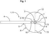
- Figure 1 shows a schematic representation of a measuring device 1 according to the invention with a measuring sensor 2, which is formed at a distal end 3 of a shaft 4.
- the shaft 4 of the measuring device 1 is inserted with its distal end 3 first into a measuring area 6 through an opening 5 matched to a size of the measuring sensor 2.
- Distance sensors 7, 8, 9 are also formed at the distal end 3 and aligned in different directions.
- the measuring sensor 2 is a volume flow sensor 10, so that the measuring device represents a flow probe 11.
- the measured variable is a flow velocity.
- the distance sensors 7, 8, 9, which are laser distance sensors, determine the distances 12, 13, 14 of the distal end 3 to the boundary 15 of the measuring area 6. The determined distances or a position of the distal end 3 of the shaft 4 and thus also of the measuring sensor 2 are recorded and/or output together with the respective measured values.
- the measuring area 6 is also multidimensional. Furthermore, an acceleration sensor 16 is arranged at the distal end 3.
- the at least one distance sensor 7, 8, 9 can be set up to continuously measure a distance 12, 13, 14.
- the measuring device has a signal generator (not shown) for outputting an optical and acoustic signal, the signal being able to be output as a function of a distance 12, 13, 14 determined by the at least one distance sensor 7, 8, 9.
- the signal generator is a combination, not shown, of a lighting element with a loudspeaker.
- the measuring device 1 shown is suitable for carrying out a method according to the invention.
- at least one distance sensor 7, 8, 9 is introduced into the two-dimensional or three-dimensional measuring area 6 using the measuring sensor 2.
- the measured variable here is a flow velocity.
- the distance sensors 7, 8, 9 With the distance sensors 7, 8, 9, at least a distance 12, 13, 14 of the measuring sensor 2 to the boundary 15 is recorded at the time of the measurement, even continuously.
- An alignment of the measuring sensor 2 and the distance sensors 7, 8, 9 in the gravitational field is determined by means of the acceleration sensor 16, which is stationarily connected to the measuring sensor 2 and the distance sensors 7, 8, 9.
- the orientation determined by the acceleration sensor 16 is used to inform a user about the orientation, for example an impermissible orientation, and is determined at the time of a measurement.
- Measured values of the measuring sensor 2 are corrected for a deviation of the alignment from an ideal and output with the associated distances 12, 13, 14 and the associated alignment. From measured values of the at least one distance sensor 7, 8, 9 and of the acceleration sensor 16, a geometric quantity, namely the shape and size of the measuring area 6, as well as a measuring location is determined. The measurement by the measuring sensor 2 takes place depending on a distance 12, 13, 14 recorded by means of the at least one distance sensor 7, 8, 9 and depending on a determined position of the measuring sensor 2 in the measuring area 6. An optical and acoustic signal is generated output when the distance 12, 13, 14 determined by means of the at least one distance sensor 7, 8, 9 corresponds to a previously determined distance and when the determined position of the measuring sensor 2 corresponds to a previously determined position. The measured values of the measuring sensor 2 are also corrected to cover the measuring range 6 by the measuring device 1.
- measuring devices 1 with measuring sensors 2 at a distal end 3 of a shaft 4, to also form at least one distance sensor 7, 8, 9 and/or an acceleration sensor 16 at this distal end 3 in order to ensure automatic distance measurement and/or determination of the distance Position and/or the orientation of the measuring sensor 2 within a measuring range 6 and thus enable the recording of spatially resolved measured values (cf. Fig. 1 ).
Landscapes
- Physics & Mathematics (AREA)
- General Physics & Mathematics (AREA)
- Fluid Mechanics (AREA)
- Length Measuring Devices With Unspecified Measuring Means (AREA)
- Measuring Pulse, Heart Rate, Blood Pressure Or Blood Flow (AREA)
Applications Claiming Priority (1)
| Application Number | Priority Date | Filing Date | Title |
|---|---|---|---|
| DE102022108402 | 2022-04-07 |
Publications (2)
| Publication Number | Publication Date |
|---|---|
| EP4257932A1 true EP4257932A1 (fr) | 2023-10-11 |
| EP4257932B1 EP4257932B1 (fr) | 2025-09-24 |
Family
ID=85873562
Family Applications (1)
| Application Number | Title | Priority Date | Filing Date |
|---|---|---|---|
| EP23166528.2A Active EP4257932B1 (fr) | 2022-04-07 | 2023-04-04 | Mesure automatique de distance dans un canal d'écoulement |
Country Status (2)
| Country | Link |
|---|---|
| US (1) | US12584778B2 (fr) |
| EP (1) | EP4257932B1 (fr) |
Citations (4)
| Publication number | Priority date | Publication date | Assignee | Title |
|---|---|---|---|---|
| DE4016529C1 (en) * | 1990-05-22 | 1991-11-07 | Turbo-Werk Messtechnik Gmbh, 5000 Koeln, De | Flowmeter for open duct - has flow sensor movable across channel to supply computer with flow speeds measured at several points |
| US6973842B1 (en) * | 2004-09-22 | 2005-12-13 | Feller Murray F | Flow probe pipe size detector |
| US20210172816A1 (en) * | 2019-12-04 | 2021-06-10 | Siemens Aktiengesellschaft | Multifunctional Sensor for the Process Industry |
| CN215573150U (zh) * | 2021-07-14 | 2022-01-18 | 合肥健威智能科技有限公司 | 一种便携式多普勒流速流量仪 |
Family Cites Families (3)
| Publication number | Priority date | Publication date | Assignee | Title |
|---|---|---|---|---|
| US6584860B1 (en) * | 2002-01-14 | 2003-07-01 | Murray F. Feller | Flow probe insertion gauge |
| WO2012132638A1 (fr) * | 2011-03-30 | 2012-10-04 | オリンパスメディカルシステムズ株式会社 | Système d'endoscope |
| WO2019232016A1 (fr) * | 2018-05-31 | 2019-12-05 | Schlumberger Technology Corporation | Débitmètre de fond de trou |
-
2023
- 2023-04-04 EP EP23166528.2A patent/EP4257932B1/fr active Active
- 2023-04-04 US US18/295,415 patent/US12584778B2/en active Active
Patent Citations (4)
| Publication number | Priority date | Publication date | Assignee | Title |
|---|---|---|---|---|
| DE4016529C1 (en) * | 1990-05-22 | 1991-11-07 | Turbo-Werk Messtechnik Gmbh, 5000 Koeln, De | Flowmeter for open duct - has flow sensor movable across channel to supply computer with flow speeds measured at several points |
| US6973842B1 (en) * | 2004-09-22 | 2005-12-13 | Feller Murray F | Flow probe pipe size detector |
| US20210172816A1 (en) * | 2019-12-04 | 2021-06-10 | Siemens Aktiengesellschaft | Multifunctional Sensor for the Process Industry |
| CN215573150U (zh) * | 2021-07-14 | 2022-01-18 | 合肥健威智能科技有限公司 | 一种便携式多普勒流速流量仪 |
Also Published As
| Publication number | Publication date |
|---|---|
| US12584778B2 (en) | 2026-03-24 |
| US20230324212A1 (en) | 2023-10-12 |
| EP4257932B1 (fr) | 2025-09-24 |
Similar Documents
| Publication | Publication Date | Title |
|---|---|---|
| EP3507227B1 (fr) | Procede d'analyse et systeme de mesure destine a mesurer une cage d'ascenseur | |
| DE102010012858B4 (de) | Vorrichtung und Verfahren zur rotatorischen Ausrichtung eines Tubenkopfes relativ zu einem Tubenkörper | |
| EP2378242B1 (fr) | Dispositif et procédé de mesure de forages | |
| EP2105242A1 (fr) | Procédé de mesure d'au moins un forage dans au moins une première surface d'un composant | |
| DE102016111570A1 (de) | Verfahren zur Ermittlung einer Linearisierungskurve zur Ermittlung des Füllstands in einem Behälter aus einer Füllhöhe sowie Verwendung eines mobilen Endgeräts hierfür | |
| DE102014210244A1 (de) | Verfahren zum Ermitteln einer geschlossenen Bahnkurve mittels eines Lasers und einem Laserlicht-Sensor und Vorrichtung zum Ermitteln einer geschlossenen Bahnkurve | |
| EP3403051B1 (fr) | Procédé et dispositif pour définir des données de consigne pour un mesurage d'une pièce à mesurer au moyen d'un appareil de mesure de coordonnées et/ou pour évaluer des résultats de mesure d'un mesurage d'une pièce mesurée au moyen d'un appareil de mesure de coordonnées | |
| EP3377846B1 (fr) | Mesure de planéité et mesure de longueur par voie tactile | |
| DE102012212210A1 (de) | Verfahren und Vorrichtung zum Bestimmen einer Höhe eines Fluidniveaus in einem Fluidbehälter | |
| EP4257932A1 (fr) | Mesure automatique de distance dans un canal d'écoulement | |
| EP3571462B1 (fr) | Procédé et dispositif de génération d'un thermogramme 3d | |
| EP1017061A1 (fr) | Méthode et dispositif pour mésurer une inhomogéneité sur une surface d'un composant d'un réacteur nucléaire et utilisation de cette méthode pour mésurer une surface pratiquement non-conductrice electrique | |
| DE10256122B4 (de) | Verfahren und Vorrichtung zur Ermittlung wenigstens einer Zustandsgröße einer Rad-Schiene-Paarung | |
| EP2950046B1 (fr) | Procédé de détermination d'une trajectoire fermée à l'aide d'un laser et d'un capteur à lumière laser et dispositif de détermination d'une trajectoire fermée | |
| WO2024125838A1 (fr) | Procédé, agencement de mesure et système de mesure d'un contour interne, en particulier d'un filetage interne sur un manchon ou une extrémité de manchon d'un tuyau | |
| EP2500615B1 (fr) | Procédé de détermination d'un diamètre de tuyau | |
| DE102005037411A1 (de) | Vorrichtung und Verfahren zur Qualitätskontrolle von Markierungen | |
| EP0887805B1 (fr) | Instrument d'exploration du profil de la paroi intérieure d'un tube | |
| DE102012103977A1 (de) | Verfahren und Vorrichtung zur Bestimmung der Oberfläche eines Objektes durch Abstandsmessung | |
| EP3519765B1 (fr) | Système de mesure à ultrasons et procédé de détection de l'épaisseur de paroi d'un tube | |
| DE102021209296B4 (de) | Verfahren zum Bestimmen der Bewegung eines mit wenigstens einer Videokamera zur Bilderfassung ausgestatteten Objekts | |
| DE102004046752A1 (de) | Messsystem | |
| DE102019204725B4 (de) | Applikationseinheit zur Dichtungsanalyse und Verfahren | |
| EP3798570B1 (fr) | Procédé d'étalonnage d'un système de mesure optique, système de mesure optique et objet d'étalonnage pour un système de mesure optique | |
| WO2011110568A1 (fr) | Procédé de validation d'un résultat de mesure d'un appareil de mesure de coordonnées |
Legal Events
| Date | Code | Title | Description |
|---|---|---|---|
| PUAI | Public reference made under article 153(3) epc to a published international application that has entered the european phase |
Free format text: ORIGINAL CODE: 0009012 |
|
| STAA | Information on the status of an ep patent application or granted ep patent |
Free format text: STATUS: THE APPLICATION HAS BEEN PUBLISHED |
|
| AK | Designated contracting states |
Kind code of ref document: A1 Designated state(s): AL AT BE BG CH CY CZ DE DK EE ES FI FR GB GR HR HU IE IS IT LI LT LU LV MC ME MK MT NL NO PL PT RO RS SE SI SK SM TR |
|
| STAA | Information on the status of an ep patent application or granted ep patent |
Free format text: STATUS: REQUEST FOR EXAMINATION WAS MADE |
|
| 17P | Request for examination filed |
Effective date: 20231220 |
|
| RBV | Designated contracting states (corrected) |
Designated state(s): AL AT BE BG CH CY CZ DE DK EE ES FI FR GB GR HR HU IE IS IT LI LT LU LV MC ME MK MT NL NO PL PT RO RS SE SI SK SM TR |
|
| GRAP | Despatch of communication of intention to grant a patent |
Free format text: ORIGINAL CODE: EPIDOSNIGR1 |
|
| STAA | Information on the status of an ep patent application or granted ep patent |
Free format text: STATUS: GRANT OF PATENT IS INTENDED |
|
| RIC1 | Information provided on ipc code assigned before grant |
Ipc: G01F 15/06 20220101ALI20250501BHEP Ipc: G01F 15/00 20060101ALI20250501BHEP Ipc: G01F 1/00 20220101ALI20250501BHEP Ipc: G01F 1/20 20060101ALI20250501BHEP Ipc: G01B 11/02 20060101ALI20250501BHEP Ipc: G01F 1/002 20220101AFI20250501BHEP |
|
| INTG | Intention to grant announced |
Effective date: 20250522 |
|
| GRAS | Grant fee paid |
Free format text: ORIGINAL CODE: EPIDOSNIGR3 |
|
| GRAA | (expected) grant |
Free format text: ORIGINAL CODE: 0009210 |
|
| STAA | Information on the status of an ep patent application or granted ep patent |
Free format text: STATUS: THE PATENT HAS BEEN GRANTED |
|
| AK | Designated contracting states |
Kind code of ref document: B1 Designated state(s): AL AT BE BG CH CY CZ DE DK EE ES FI FR GB GR HR HU IE IS IT LI LT LU LV MC ME MK MT NL NO PL PT RO RS SE SI SK SM TR |
|
| REG | Reference to a national code |
Ref country code: GB Ref legal event code: FG4D Free format text: NOT ENGLISH |
|
| REG | Reference to a national code |
Ref country code: CH Ref legal event code: EP |
|
| REG | Reference to a national code |
Ref country code: DE Ref legal event code: R096 Ref document number: 502023001837 Country of ref document: DE |
|
| REG | Reference to a national code |
Ref country code: IE Ref legal event code: FG4D Free format text: LANGUAGE OF EP DOCUMENT: GERMAN |
|
| PG25 | Lapsed in a contracting state [announced via postgrant information from national office to epo] |
Ref country code: NO Free format text: LAPSE BECAUSE OF FAILURE TO SUBMIT A TRANSLATION OF THE DESCRIPTION OR TO PAY THE FEE WITHIN THE PRESCRIBED TIME-LIMIT Effective date: 20251224 |
|
| REG | Reference to a national code |
Ref country code: LT Ref legal event code: MG9D |
|
| PG25 | Lapsed in a contracting state [announced via postgrant information from national office to epo] |
Ref country code: FI Free format text: LAPSE BECAUSE OF FAILURE TO SUBMIT A TRANSLATION OF THE DESCRIPTION OR TO PAY THE FEE WITHIN THE PRESCRIBED TIME-LIMIT Effective date: 20250924 |
|
| PG25 | Lapsed in a contracting state [announced via postgrant information from national office to epo] |
Ref country code: HR Free format text: LAPSE BECAUSE OF FAILURE TO SUBMIT A TRANSLATION OF THE DESCRIPTION OR TO PAY THE FEE WITHIN THE PRESCRIBED TIME-LIMIT Effective date: 20250924 |
|
| PG25 | Lapsed in a contracting state [announced via postgrant information from national office to epo] |
Ref country code: GR Free format text: LAPSE BECAUSE OF FAILURE TO SUBMIT A TRANSLATION OF THE DESCRIPTION OR TO PAY THE FEE WITHIN THE PRESCRIBED TIME-LIMIT Effective date: 20251225 |
|
| PG25 | Lapsed in a contracting state [announced via postgrant information from national office to epo] |
Ref country code: SE Free format text: LAPSE BECAUSE OF FAILURE TO SUBMIT A TRANSLATION OF THE DESCRIPTION OR TO PAY THE FEE WITHIN THE PRESCRIBED TIME-LIMIT Effective date: 20250924 |
|
| PG25 | Lapsed in a contracting state [announced via postgrant information from national office to epo] |
Ref country code: LV Free format text: LAPSE BECAUSE OF FAILURE TO SUBMIT A TRANSLATION OF THE DESCRIPTION OR TO PAY THE FEE WITHIN THE PRESCRIBED TIME-LIMIT Effective date: 20250924 |
|
| PG25 | Lapsed in a contracting state [announced via postgrant information from national office to epo] |
Ref country code: BG Free format text: LAPSE BECAUSE OF FAILURE TO SUBMIT A TRANSLATION OF THE DESCRIPTION OR TO PAY THE FEE WITHIN THE PRESCRIBED TIME-LIMIT Effective date: 20250924 |
|
| PG25 | Lapsed in a contracting state [announced via postgrant information from national office to epo] |
Ref country code: RS Free format text: LAPSE BECAUSE OF FAILURE TO SUBMIT A TRANSLATION OF THE DESCRIPTION OR TO PAY THE FEE WITHIN THE PRESCRIBED TIME-LIMIT Effective date: 20251224 |
|
| REG | Reference to a national code |
Ref country code: NL Ref legal event code: MP Effective date: 20250924 |
|
| PG25 | Lapsed in a contracting state [announced via postgrant information from national office to epo] |
Ref country code: NL Free format text: LAPSE BECAUSE OF FAILURE TO SUBMIT A TRANSLATION OF THE DESCRIPTION OR TO PAY THE FEE WITHIN THE PRESCRIBED TIME-LIMIT Effective date: 20250924 |
|
| PG25 | Lapsed in a contracting state [announced via postgrant information from national office to epo] |
Ref country code: SM Free format text: LAPSE BECAUSE OF FAILURE TO SUBMIT A TRANSLATION OF THE DESCRIPTION OR TO PAY THE FEE WITHIN THE PRESCRIBED TIME-LIMIT Effective date: 20250924 |
|
| PG25 | Lapsed in a contracting state [announced via postgrant information from national office to epo] |
Ref country code: ES Free format text: LAPSE BECAUSE OF FAILURE TO SUBMIT A TRANSLATION OF THE DESCRIPTION OR TO PAY THE FEE WITHIN THE PRESCRIBED TIME-LIMIT Effective date: 20250924 |
|
| PG25 | Lapsed in a contracting state [announced via postgrant information from national office to epo] |
Ref country code: IT Free format text: LAPSE BECAUSE OF FAILURE TO SUBMIT A TRANSLATION OF THE DESCRIPTION OR TO PAY THE FEE WITHIN THE PRESCRIBED TIME-LIMIT Effective date: 20250924 |
|
| PG25 | Lapsed in a contracting state [announced via postgrant information from national office to epo] |
Ref country code: IS Free format text: LAPSE BECAUSE OF FAILURE TO SUBMIT A TRANSLATION OF THE DESCRIPTION OR TO PAY THE FEE WITHIN THE PRESCRIBED TIME-LIMIT Effective date: 20260124 |
|
| PG25 | Lapsed in a contracting state [announced via postgrant information from national office to epo] |
Ref country code: CZ Free format text: LAPSE BECAUSE OF FAILURE TO SUBMIT A TRANSLATION OF THE DESCRIPTION OR TO PAY THE FEE WITHIN THE PRESCRIBED TIME-LIMIT Effective date: 20250924 Ref country code: PT Free format text: LAPSE BECAUSE OF FAILURE TO SUBMIT A TRANSLATION OF THE DESCRIPTION OR TO PAY THE FEE WITHIN THE PRESCRIBED TIME-LIMIT Effective date: 20260126 |
|
| PG25 | Lapsed in a contracting state [announced via postgrant information from national office to epo] |
Ref country code: PL Free format text: LAPSE BECAUSE OF FAILURE TO SUBMIT A TRANSLATION OF THE DESCRIPTION OR TO PAY THE FEE WITHIN THE PRESCRIBED TIME-LIMIT Effective date: 20250924 |
|
| PG25 | Lapsed in a contracting state [announced via postgrant information from national office to epo] |
Ref country code: EE Free format text: LAPSE BECAUSE OF FAILURE TO SUBMIT A TRANSLATION OF THE DESCRIPTION OR TO PAY THE FEE WITHIN THE PRESCRIBED TIME-LIMIT Effective date: 20250924 Ref country code: SK Free format text: LAPSE BECAUSE OF FAILURE TO SUBMIT A TRANSLATION OF THE DESCRIPTION OR TO PAY THE FEE WITHIN THE PRESCRIBED TIME-LIMIT Effective date: 20250924 |