EP4257988A1 - Verfahren zum lokalisieren eines fehlerpunktes auf einem hochspannungs-drehstromkabel und system zum lokalisieren eines fehlerpunktes - Google Patents
Verfahren zum lokalisieren eines fehlerpunktes auf einem hochspannungs-drehstromkabel und system zum lokalisieren eines fehlerpunktes Download PDFInfo
- Publication number
- EP4257988A1 EP4257988A1 EP22382332.9A EP22382332A EP4257988A1 EP 4257988 A1 EP4257988 A1 EP 4257988A1 EP 22382332 A EP22382332 A EP 22382332A EP 4257988 A1 EP4257988 A1 EP 4257988A1
- Authority
- EP
- European Patent Office
- Prior art keywords
- snf
- fault
- shield
- jwi
- cnf
- Prior art date
- Legal status (The legal status is an assumption and is not a legal conclusion. Google has not performed a legal analysis and makes no representation as to the accuracy of the status listed.)
- Granted
Links
Images



Classifications
-
- G—PHYSICS
- G01—MEASURING; TESTING
- G01R—MEASURING ELECTRIC VARIABLES; MEASURING MAGNETIC VARIABLES
- G01R19/00—Arrangements for measuring currents or voltages or for indicating presence or sign thereof
- G01R19/25—Arrangements for measuring currents or voltages or for indicating presence or sign thereof using digital measurement techniques
- G01R19/2513—Arrangements for monitoring electric power systems, e.g. power lines or loads; Logging
-
- G—PHYSICS
- G01—MEASURING; TESTING
- G01R—MEASURING ELECTRIC VARIABLES; MEASURING MAGNETIC VARIABLES
- G01R19/00—Arrangements for measuring currents or voltages or for indicating presence or sign thereof
- G01R19/0092—Measuring current only
-
- G—PHYSICS
- G01—MEASURING; TESTING
- G01R—MEASURING ELECTRIC VARIABLES; MEASURING MAGNETIC VARIABLES
- G01R31/00—Arrangements for testing electric properties; Arrangements for locating electric faults; Arrangements for electrical testing characterised by what is being tested not provided for elsewhere
- G01R31/08—Locating faults in cables, transmission lines, or networks
- G01R31/081—Locating faults in cables, transmission lines, or networks according to type of conductors
- G01R31/083—Locating faults in cables, transmission lines, or networks according to type of conductors in cables, e.g. underground
-
- G—PHYSICS
- G01—MEASURING; TESTING
- G01R—MEASURING ELECTRIC VARIABLES; MEASURING MAGNETIC VARIABLES
- G01R31/00—Arrangements for testing electric properties; Arrangements for locating electric faults; Arrangements for electrical testing characterised by what is being tested not provided for elsewhere
- G01R31/08—Locating faults in cables, transmission lines, or networks
- G01R31/088—Aspects of digital computing
-
- G—PHYSICS
- G01—MEASURING; TESTING
- G01R—MEASURING ELECTRIC VARIABLES; MEASURING MAGNETIC VARIABLES
- G01R31/00—Arrangements for testing electric properties; Arrangements for locating electric faults; Arrangements for electrical testing characterised by what is being tested not provided for elsewhere
- G01R31/50—Testing of electric apparatus, lines, cables or components for short-circuits, continuity, leakage current or incorrect line connections
- G01R31/52—Testing for short-circuits, leakage current or ground faults
-
- G—PHYSICS
- G01—MEASURING; TESTING
- G01R—MEASURING ELECTRIC VARIABLES; MEASURING MAGNETIC VARIABLES
- G01R31/00—Arrangements for testing electric properties; Arrangements for locating electric faults; Arrangements for electrical testing characterised by what is being tested not provided for elsewhere
- G01R31/50—Testing of electric apparatus, lines, cables or components for short-circuits, continuity, leakage current or incorrect line connections
- G01R31/58—Testing of lines, cables or conductors
Definitions
- the present invention relates to a method for locating a fault point on a high-voltage three-phase AC cable and to a system for locating a fault point.
- US20210072302A1 relates to a method for locating a fault point on a high-voltage cable based on providing at least two current measuring apparatuses arranged at the cable at a given distance and having timers synchronized with one another, and a measuring device for detecting an electric current flowing in the shield and/or an earthing line connecting the shield and earth.
- the measuring apparatus transmits pairs of current measurement values and associated values of the timer to an analysis unit which, upon the occurrence of a current exceeding a threshold value and/or of a current profile over time that satisfies specific stipulations, feeds to a calculation unit the associated values of the timers and also an indication about the location of the measurement, for which first effects of the short circuit occurred.
- the calculation unit calculates the location of the fault from the known distance between the measuring apparatuses and a difference between the values of the synchronized timers.
- the object of the invention is to provide a method for locating a fault point on a high-voltage three-phase AC cable, and a system for locating a fault point on a high-voltage three-phase AC cable, as defined in the claims.
- a first aspect of the invention relates to a method for locating a fault point on a high-voltage three-phase AC cable.
- the cable in which the method of the invention is applied comprises a first end, a second end, and at least one main section extending between said ends, the cable comprising one conductor per phase and three shields associated with said conductor, said shields being attached to one another and connected to ground at both ends of each main section. Therefore, the method of the invention is configured for being applied in cables with cross bonding connection systems of the shields and in cables with solid bonded connection systems.
- the method comprises the following steps
- a second aspect of the invention relates to a system for locating a fault point on a cable such as the one described in the first aspect of the invention, the system comprising:
- the method for locating and the system for locating of the invention offer a rapid solution for locating a fault point on a high-voltage three-phase AC cable, with the result virtually being obtained in real time.
- the fault resistance i.e., the resistance between the conductor in fault and the shield in fault at fault point F, nor is it necessary to know the ground resistance of the connections to ground of the shields.
- a first aspect of the invention relates to a method for locating a fault point F on a high-voltage three-phase AC cable 1.
- the method of the invention is configured for locating a fault point F on a cable 1 comprising a first end 10, a second end 11, and at least one main section MP 1 , MP 2 , MP 3 extending between said ends 10, 11.
- the cable 1 comprises one conductor R, S, T for each phase and three shields S A , S B , Sc; S R , S S , S T associated with said conductors R, S, T.
- the shields S A , S B , Sc; S R , S S , S T are attached to one another and connected to ground G at both ends of each main section MP 1 , MP 2 , MP 3 , preferably by means of a corresponding grounding device 3, 4. Therefore, the method of the invention is configured for being applied in cables 1 with shield cross bonding connection systems, and in cables with solid bonded connection systems.
- fault point F is considered the point where one of the conductors R, S, T, of the cable 1 has electrical contact with the corresponding shield S A , S B , S C ; S R , S S , S T , such that a short circuit occurs between said conductor R, S, T and the corresponding shield S A , S B , Sc; S R , S S , S T at said fault point F.
- main section in fault will be considered the main section MP 1 , MP 2 , MP 3 of cable 1 at which the fault point F is arranged.
- the method of the invention comprises the following steps:
- the conductor current I R1 ; I S1 ; I T1 measured at the first end 10 of the cable 1 for each conductor R, S, T is compared with the conductor current I R2 ; I S2 ; I T2 measured at the second end 11 of the cable 1, determining that the conductor R, S, T in fault will be the conductor in which the conductor current I R1 , I R2 ; I S1 , I S2 ; I T1 , I T2 at said ends 10, 11 is different.
- the main section MP 1 , MP 2 , MP 3 in fault is determined taking into account that at the ends of said main section MP 1 , MP 2 , MP 3 in fault, the shield currents I SA1 , I SB1 , I SC1 ; I SA2 , I SB2 , I SC2 ; I SA3 , I SB3 , I SC3 ; I SA4 , I SB4 , I SC4 are not in phase.
- the shield currents I SA1 , I SB1 , I SC1 ; I SA2 , I SB2 , I SC2 ; I SA3 , I SB3 , I SC3 ; I SA4 , I SB4 , I SC4 are successively analyzed starting from one of the ends 10, 11 of the cable 1 until observing that the shield currents I SA1 , I SB1 , I SC1 ; I SA2 , I SB2 , I SC2 ; I SA3 , I SB3 , I SC3 ; I SA4 , I SB4 , I SC4 are not in phase, determining that the main section MP 1 , MP 2 , MP 3 in fault will be the main section MP 1 , MP 2 , MP 3 after the connection point to ground G in which it is detected that said shield currents I SA1 , I SB1 , I SB1
- the main section in fault will be determined by observing said shield currents and seeing at which point they are out of phase, or alternatively detecting the main part in which for one of the shields the shield current at both ends of the main section in fault is different.
- each main section MP 1 , MP 2 , MP 3 comprises three minor sections mp 1 , mp 2 , mp 3 , the method comprising determining the minor section mp 1 , mp 2 , mp 3 in fault once the main section MP 1 , MP 2 , MP 3 in fault has been determined.
- the shield S A , S B , S C in fault is determined by comparing for each shield S A , S B , S C the shield current I SA1 , I SB1 , I SC1 ; I SA2 , I SB2 , I SC2 ; I SA3 , I SB3 , I SC3 ; I SA4 , I SB4 , I SC4 measured at one of the ends of the main part MP 1 , MP 2 , MP 3 in fault with the shield current I SA1 , I SB1 , I SC1 ; I SA2 , I SB2 , I SC2 ; I SA3 , I SB3 , I SC3 ; I SA4 , I SB4 , I SC4 measured at the other end of the main part MP 1 , MP 2 , MP 3 in fault, the shield S A , S B , S C in fault being the shield SA, SB, Sc whose current I SA1 ,
- the minor section mp 1 , mp 2 , mp 3 in fault will be the minor section mp 1 , mp 2 , mp 3 in which the conductor R, S, T in fault and the shield S A , S B , S C in fault coincide. It should be pointed out that the case of the cables with a cross bonding connection system, the minor part mp 1 , mp 2 , mp 3 in fault is determined univocally, since the determination of said minor part mp 1 , mp 2 , mp 3 in fault is performed from the short circuit values, without the need for models or suppositions.
- the model of the shields S A , S B , S C of main section MP 1 , MP 2 , MP 3 in fault of each shield S A , S B , S C comprises per minor section mp 1 , mp 2 , mp 3 its own resistance R SA , R SB , Rsc and its own self-inductance L SA , L SB , L SC of the corresponding shield SA, SB, Sc, the mutual inductance M SB-SA , M SC-SA ; M SA-SB , M SC-SB ; M SA-SC , M SB-SC between said shield S A , S B , Sc and the rest of the shields S A , S B , Sc, and the mutual inductance M R-SA , M S-SA , M T-SA ; M R-SB , M S-SB , M T-SB ; M R-SC , M S-SC , M T-SC between said shield S A
- the capacitive resistance between said shield and the rest of the shields and the conductors is not taken into account, since in case of fault, as the currents are very high and the frequency is the nominal frequency of the facility, they are completely negligible.
- the model of shield of each shield S A , S B , Sc does not include the admittance between said shield and the rest of the shields and the conductors, since they are values that contribute nothing in fault situations.
- the parameters that are considered to define the model of the shield for each shield S A , S B , Sc are the following:
- the shields S A , S B , Sc are attached and connected to ground at both ends of each main section MP 1 , MP 2 , MP 3 .
- the ends of the model corresponding to each shield S A , S B , Sc are attached to one another, such that three nets in which the sum of voltages is zero are formed, the only unknown being the distance x to the fault point F.
- V SF V SNF
- V SF V SF _ mpf + V SF _ mpnf 1 + V SF _ mpnf 2
- V SF mpf xI SF 1 R SF mpf + xjwI SF 1 L SF mpf + xjwI CF 1 M CF ⁇ SF mpf + xjwI CNF 1 M CNF 1 ⁇ SF mpf + xjwI CNF 2 M CNF 2 ⁇ SF mpf + xjwI SNF 1 M SNF 1 ⁇ SF mpf + xjwI SNF 2 M SNF 2 ⁇ SF mpf ⁇ 1 ⁇ x I SF 2 R SF mpf ⁇ 1 ⁇ x jwI SF 2 L SF mpf ⁇ 1 ⁇ x xjwI
- the cable 1 comprises a single main section MP 1 .
- the model of the shields S R , S S , S T of each shield S R , S S , S T comprises its own resistance R SR , R SS , R ST and self-inductance L SR , L SS , L ST , the mutual inductance M SS-SR , M ST-SR ; M SR-SS , M ST-SS ; M SR-ST , M SS-ST between said shield S R , S S , S T and the rest of the shields S R , S S , S T and the mutual inductance M R-SR , M S-SR , M T-SR ; M R-SS , M S-SS , M T-SS ; M R-ST , M S-ST , M T-ST between said shield S R , S S , S T and the conductors R, S, T.
- the shields S R , S S , S T are attached and connected to ground at both ends of the main section MP 1 . For this reason, the ends of the models corresponding to each shield S R , S S , S T are attached to one another, such that three nets in which the sum of voltages is zero are formed, the only unknown being the distance x to the fault point F.
- V SF xI SF 1 R SF + xjwI SF 1 L SF + xjwI CF 1 M CF ⁇ SF + xjwI CNF 1 M CNF 1 ⁇ SF + xjwI CNF 2 M CNF 2 ⁇ SF + xjwI SNF 1 M SNF 1 ⁇ SF + xjwI SNF 2 M SNF 2 ⁇ SF ⁇ 1 ⁇ x I SF 2 R SF ⁇ 1 ⁇ x jwI SF 2 L SF ⁇ 1 ⁇ x jwI CF 2 M CF ⁇ SF + 1 ⁇ x jwI CNF 1 M CNF 1 ⁇ SF + 1 ⁇ x jwI CNF 2 M C
- a second aspect of the invention relates to a system for locating a fault point F on a high-voltage three-phase AC cable 1.
- the system of the invention is configured for locating a fault point F on a cable 1 comprising a first end 10, a second end 11, and at least one main section MP 1 , MP 2 , MP 3 extending between said ends 10, 11.
- the cable 1 comprises one conductor R, S, T per phase and three shields S A , S B , S C ; S R , S S , S T associated with said conductors R, S, T.
- the shields S A , S B , S C ; S R , S S , S T are attached to one another and connected to ground G at both ends of each main section MP 1 , MP 2 , MP 3 .
- the system of the invention comprises
- Figure 1 schematically shows a first embodiment of the system of the invention, said system being applied on a high-voltage three-phase AC cable 1 having a first cable configuration.
- the cable 1 according to the first configuration has a cross bonding connection system.
- the cable 1 comprises a first end 10, a second end 11, and three main sections MP 1 , MP 2 , MP 3 extending between said ends 10, 11.
- the shields S A , S B , Sc are attached to one another and connected to ground G at both ends of each main section MP 1 , MP 2 , MP 3 .
- Each main section MP 1 , MP 2 , MP 3 comprises three minor sections mp 1 , mp 2 , mp 3 which are defined by the points where the shields S A , S B , Sc are cross bonded.
- the system comprises a first current measuring equipment configured for measuring the conductor current I R1 , I S1 , I T1 , I R2 , I S2 , I T2 circulating through each conductor R, S, T both at the first end 10 and at the second end 11 of the cable 1.
- the first current measuring equipment comprises six current sensors 50, 51, 52, 53, 54, 55, with one current sensor 50, 51, 52, 53, 54, 55 being arranged at each end of each conductor R, S, T.
- the system comprises a second current measuring equipment configured for measuring the shield current I SA1 , I SB1 , I SC1 ; I SA2 , I SB2 , I SC2 ; I SA3 , I SB3 , I SC3 ; I SA4 , I SB4 , I SC4 of each shield S A , S B , S C in the vicinity of the connection points to ground G of the shields S A , S B , Sc.
- the second current measuring equipment comprises twelve current sensors 60, 61, 62, 63, 64, 65, 66, 67, 68, 69, 70, 71, with one current sensor 60, 61, 62, 63, 64, 65, 66, 67, 68, 69, 70, 71 being arranged in the vicinity of the connection points to ground G of each shield S A , S B , Sc.
- shield currents I SA1 , I SB1 , I SC1 , I SA2 , I SB2 , I SC2 at the ends 10, 11 of the cable 1 is exclusive to the corresponding main section MP 1 , MP 3 (only shield current measurement)
- the measurement of shield currents I SA3 , I SB3 , I SC3 ; I SA4 , I SB4 , I SC4 in the intermediate connections to ground G does not present said separation, since the shields S A , S B , Sc are attached to the corresponding grounding device 3, 4 through a coaxial cable 30, as shown for example in Figure 1 .
- the system of the invention comprises a processor, not shown in the figures, configured for executing the method of the invention based on the current measurements performed by said current measuring equipment.
- a fault between the conductor S and the shield S B in the main section MP 2 and the minor section mp 2 has been depicted in Figures 1 and 2 .
- the method of the invention would be applied as follows: Measuring the conductor current I R1 , I S1 , I T1 , I R2 , I S2 , I T2 circulating through each conductor R, S, T both at the first end 10 and at the second end 11 of the cable 1 by means of the first current measuring equipment.
- the shield currents I SA1 , I SB1 , I SC1 ; I SA2 , I SB2 , I SC2 ; I SA3 , I SB3 , I SC3 ; I SA4 , I SB4 , I SC4 are successively analyzed starting from one of the ends 10, 11 of the cable 1, for example starting from the first end 10.
- the main section MP 1 is the section that is in fault, and therefore the shield currents I SA2 , I SB2 , I SC2 in the following connection point to ground G are analyzed.
- the shields S A , S B , Sc are attached to one another at both ends of each main section MP 1 , MP 2 , MP 3 , in the main section MP 2 in fault the shield currents I SA3 , I SB3 , I SC3 ; I SA4 , I SB4 , I SC4 , are out of phase, but once the shield currents I SA3 , I SB3 , I SC3 ; I SA4 , I SB4 , I SC4 reach the end of the main section MP 2 in fault, in the rest of the main sections MP 1 , MP 3 the distribution of the shield currents I SA1 , I SB1 , I SC1 ; I SA2 , I SB2 , I SC2 is the same for all the shields S A , S B , Sc.
- the minor section mp 1 , mp 2 , mp 3 is determined.
- the shield S A , S B , S C in fault is determined by comparing for each shield S A , S B , S C the shield current I SA2 , I SB2 , I SC2 measured at one of the ends of the main part MP 2 in fault with the shield current I SA3 , I SB3 , I SC3 measured at the other end of the main part MP 2 in fault.
- the shield current I SB3 at the first end of the main section MP 2 in fault will be different from the shield current I SB4 at the second end of the main section MP 2 in fault, determining that the shield S B is the section that is in fault.
- the minor section mp 1 , mp 2 , mp 3 in fault will be the minor section mp 2 in which the conductor S in fault and the shield S B in fault coincide.
- the model of the shields S A , S B , S C of main section MP 2 in fault is defined.
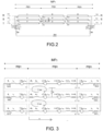
- the model of the shields S A , S B , S C of the main section MP 2 in fault are observed in Figure 3 .
- the shields S A , S B , Sc are attached to one another at the ends of the main part MP 2 in fault, three nets S A -S B , S A -S C , S B -S C in which the sum of the voltages is equal to zero, or in other words, the voltage at the ends of the shields is the same for the three shields, are created.
- Figure 4 shows in detail the model of the shield S B which is in fault
- Figure 5 shows said model of the shield S B which is in fault in which the mutual inductances are depicted as generators.
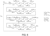
- Figure 6 shows the model of the shield S A which is not in fault in which the mutual inductances are depicted as generators.
- each shield S A , S B , S C comprises per minor section mp 1 , mp 2 , mp 3 its own resistance R SA , R SB , Rsc and its own self-inductance L SA , L SB , Lsc of the corresponding shield S A , S B , S C , the mutual inductance M SB-SA , M SC-SA ; M SA-SB , M SC-SB ; M SA-SC , M SB-SC between said shield S A , S B , Sc and the rest of the shields S A , S B , S C , and the mutual inductance M R-SA , M S-SA , M T-SA ; M R-SB , M S-SB , M T-SB ; M R-SC , M S-SC , M T-SC between said shield S A , S B , Sc and the conductors R, S, T.
- V SB I SB 3 R SB 1 + jwI SB 3 L SB 1 + jwI R M R ⁇ SB 1 + jwI S 1 M S ⁇ SB 1 + jwI T M T ⁇ SB 1 + jwI SA 3 M SA 1 ⁇ SB 1 + jwI SC 3 M SC 1 ⁇ SB 1 xI SB 3 R SB 2 + xjwI SB 3 L SB 2 + xjwI R M R ⁇ SB 2 + xjwI S 1 M S ⁇ SB 2 + xjwI T M T ⁇ SB 2 + xjwI SA 3 M SA 2 ⁇ SB 2 + xjwI SC 3 M SC 2 ⁇ SB 2 ⁇ 1 ⁇ x I SB 4 R SB 2 ⁇ 1 ⁇ x jwI SB 4 L SB 2 + 1 ⁇ x jwI R M R ⁇ SB 2 ⁇ 1 ⁇ x jwI R M R ⁇ SB 2 ⁇ 1 ⁇ x jwI SB 4 L SB 2 + 1
- Figure 7 schematically shows a second embodiment of the system of the invention, said system being applied on a high-voltage three-phase AC cable 1 having a second cable configuration.
- the cable 1 according to the second configuration has a solid bonded connection system.
- the cable 1 comprises a first end 10, a second end 11, and a single main section MP 1 extending between said ends 10, 11.
- the cable 1 comprises one conductor R, S, T and one shield S R , Ss, S T per phase.
- the shields S R , S S , S T are attached to one another and connected to ground G at both ends of the main section MP 1 .
- the system comprises a first current measuring equipment configured for measuring the conductor current I R1 , I S1 , I T1 , I R2 , I S2 , I T2 circulating through each conductor R, S, T both at the first end 10 and at the second end 11 of the cable 1.
- the first current measuring equipment comprises six current sensors 50, 51, 52, 53, 54, 55, with one current sensor 50, 51, 52, 53, 54, 55 being arranged at each end of each conductor R, S, T.
- the system comprises a second current measuring equipment configured for measuring the shield current I SR1 , I SS1 , I ST1 ; I SR2 , I SS2 , I ST2 ; of each shield S R , Ss, S T in the vicinity of the connection points to ground G of the shields S R , S S , S T .
- the second current measuring equipment comprises six current sensors 60, 61, 62, 63, 64, 65, with one current sensor 60, 61, 62, 63, 64, 65 being arranged in the vicinity of the connection points to ground G of each shield S R , Ss, S T .
- the system of the invention comprises a processor, not shown in the figures, configured for executing the method of the invention based on the current measurements performed by said current measuring equipment 50, 51, 52, 53, 54, 55, 60, 61, 62, 63, 64, 65.
- a fault between the conductor S and the shield Ss has been depicted in Figure 7 .
- the method of the invention would be applied as follows: Measuring the conductor current I R1 , I S1 , I T1 , I R2 , I S2 , I T2 circulating through each conductor R, S, T both at the first end 10 and at the second end 11 of the cable 1 by means of the first current measuring equipment 5.
- each shield S R , S S , S T comprises its own resistance Rss, R SR , Rsc and its own self-inductance Lss, L SR , L ST of the corresponding shield S R , S S , S T , the mutual inductance Mss-S R , M ST-SR ; M SR-SS , M ST-SS ; M SR-ST , M SS-ST between said shield S R , S S , S T and the rest of the shields S R , S S , S T , and the mutual inductance M R-SR , M S-SR , M T-SR ; M R-SS , M S-SS , M T-SS ; M R-ST , M S-ST , M T-ST between said shield S R , S S , S T and the conductors R, S, T.
- the shields S R , S S , S T are attached and connected to ground at both ends of the main section MP 1 . For this reason, in the model of the shields S R , S S , S T the ends of the models corresponding to each shield S A , S B , Sc are attached to one another, such that three nets in which the sum of voltages is zero are formed.
- FIG 8 shows the detailed model of the shields S R and Ss.
Landscapes
- Physics & Mathematics (AREA)
- General Physics & Mathematics (AREA)
- Engineering & Computer Science (AREA)
- Mathematical Physics (AREA)
- Theoretical Computer Science (AREA)
- Power Engineering (AREA)
- Locating Faults (AREA)
Priority Applications (3)
| Application Number | Priority Date | Filing Date | Title |
|---|---|---|---|
| ES22382332T ES3008713T3 (en) | 2022-04-06 | 2022-04-06 | Method for locating a fault point on a high-voltage three-phase ac cable, and system for locating a fault point |
| EP22382332.9A EP4257988B1 (de) | 2022-04-06 | 2022-04-06 | Verfahren zum lokalisieren eines fehlerpunktes auf einem hochspannungs-drehstromkabel und system zum lokalisieren eines fehlerpunktes |
| US18/129,351 US12282050B2 (en) | 2022-04-06 | 2023-03-31 | Method for locating a fault point on a high-voltage three-phase AC cable, and system for locating a fault point |
Applications Claiming Priority (1)
| Application Number | Priority Date | Filing Date | Title |
|---|---|---|---|
| EP22382332.9A EP4257988B1 (de) | 2022-04-06 | 2022-04-06 | Verfahren zum lokalisieren eines fehlerpunktes auf einem hochspannungs-drehstromkabel und system zum lokalisieren eines fehlerpunktes |
Publications (3)
| Publication Number | Publication Date |
|---|---|
| EP4257988A1 true EP4257988A1 (de) | 2023-10-11 |
| EP4257988C0 EP4257988C0 (de) | 2025-01-01 |
| EP4257988B1 EP4257988B1 (de) | 2025-01-01 |
Family
ID=81850040
Family Applications (1)
| Application Number | Title | Priority Date | Filing Date |
|---|---|---|---|
| EP22382332.9A Active EP4257988B1 (de) | 2022-04-06 | 2022-04-06 | Verfahren zum lokalisieren eines fehlerpunktes auf einem hochspannungs-drehstromkabel und system zum lokalisieren eines fehlerpunktes |
Country Status (3)
| Country | Link |
|---|---|
| US (1) | US12282050B2 (de) |
| EP (1) | EP4257988B1 (de) |
| ES (1) | ES3008713T3 (de) |
Cited By (1)
| Publication number | Priority date | Publication date | Assignee | Title |
|---|---|---|---|---|
| CN121164829A (zh) * | 2025-11-20 | 2025-12-19 | 内蒙古电力(集团)有限责任公司呼和浩特供电分公司 | 护层接地环流在线监测与故障源定位诊断方法及系统 |
Citations (1)
| Publication number | Priority date | Publication date | Assignee | Title |
|---|---|---|---|---|
| US20210072302A1 (en) | 2019-08-29 | 2021-03-11 | Nexans | Method and system for localizing a short circuit between a conductor and an electrically conductive shield surrounding said conductor |
Family Cites Families (8)
| Publication number | Priority date | Publication date | Assignee | Title |
|---|---|---|---|---|
| JPS61243375A (ja) * | 1985-04-19 | 1986-10-29 | Tokyo Electric Power Co Inc:The | 電力ケ−ブルの絶縁体劣化診断法 |
| US5202812A (en) * | 1988-09-21 | 1993-04-13 | Ngk Insulators, Ltd. | Apparatus for detecting faults on power transmission lines |
| US7282944B2 (en) * | 2003-07-25 | 2007-10-16 | Power Measurement, Ltd. | Body capacitance electric field powered device for high voltage lines |
| US7683798B2 (en) * | 2006-07-07 | 2010-03-23 | Ssi Power, Llc | Current monitoring device for high voltage electric power lines |
| US10852359B2 (en) * | 2017-12-05 | 2020-12-01 | The University Of Hong Kong | Apparatus and method for DC-component-based fault classification of three-phase distribution power cables with magnetic sensing |
| EP3850381A2 (de) * | 2018-09-10 | 2021-07-21 | 3M Innovative Properties Company | Stromkabelüberwachungsvorrichtung mit teilentladungssensor |
| US11971440B2 (en) * | 2018-11-01 | 2024-04-30 | University Of Manitoba | Method for determining conductors involved in a fault on a power transmission line and fault location using local current measurements |
| EP4257987B1 (de) * | 2022-04-06 | 2025-01-01 | Lumiker Aplicaciones Tecnologicas S.L. | Verfahren zum lokalisieren eines fehlerpunktes auf einem hochspannungs-drehstromkabel und system zum lokalisieren eines fehlerpunktes |
-
2022
- 2022-04-06 EP EP22382332.9A patent/EP4257988B1/de active Active
- 2022-04-06 ES ES22382332T patent/ES3008713T3/es active Active
-
2023
- 2023-03-31 US US18/129,351 patent/US12282050B2/en active Active
Patent Citations (1)
| Publication number | Priority date | Publication date | Assignee | Title |
|---|---|---|---|---|
| US20210072302A1 (en) | 2019-08-29 | 2021-03-11 | Nexans | Method and system for localizing a short circuit between a conductor and an electrically conductive shield surrounding said conductor |
Non-Patent Citations (4)
| Title |
|---|
| DONG XIANG ET AL: "Online Monitoring and Diagnosis of HV Cable Faults by Sheath System Currents", IEEE TRANSACTIONS ON POWER DELIVERY, IEEE SERVICE CENTER, NEW YORK, NY, US, vol. 32, no. 5, 1 October 2017 (2017-10-01), pages 2281 - 2290, XP011659419, ISSN: 0885-8977, [retrieved on 20170822], DOI: 10.1109/TPWRD.2017.2665818 * |
| LI MINGZHEN ET AL: "A Revised Model for Calculating HV Cable Sheath Current Under Short-Circuit Fault Condition and Its Application for Fault Location-Part 1: The Revised Model", IEEE TRANSACTIONS ON POWER DELIVERY, IEEE SERVICE CENTER, NEW YORK, NY, US, vol. 34, no. 4, 1 August 2019 (2019-08-01), pages 1674 - 1683, XP011736336, ISSN: 0885-8977, [retrieved on 20190724], DOI: 10.1109/TPWRD.2019.2918159 * |
| MINGZHEN LI ET AL: "A novel fault localization method based on monitoring of sheath current in a cross-bonded HV cable system", 2017 IEEE ELECTRICAL INSULATION CONFERENCE (EIC), IEEE, 11 June 2017 (2017-06-11), pages 123 - 126, XP033138823, ISBN: 978-1-5090-3965-4, [retrieved on 20170808], DOI: 10.1109/EIC.2017.8004678 * |
| ZHOU CHENGKE ET AL: "An integrated cable condition diagnosis and fault localization system via sheath current monitoring", 2016 INTERNATIONAL CONFERENCE ON CONDITION MONITORING AND DIAGNOSIS (CMD), IEEE, 25 September 2016 (2016-09-25), pages 1 - 8, XP033013422, DOI: 10.1109/CMD.2016.7757837 * |
Cited By (1)
| Publication number | Priority date | Publication date | Assignee | Title |
|---|---|---|---|---|
| CN121164829A (zh) * | 2025-11-20 | 2025-12-19 | 内蒙古电力(集团)有限责任公司呼和浩特供电分公司 | 护层接地环流在线监测与故障源定位诊断方法及系统 |
Also Published As
| Publication number | Publication date |
|---|---|
| EP4257988C0 (de) | 2025-01-01 |
| US12282050B2 (en) | 2025-04-22 |
| US20230324450A1 (en) | 2023-10-12 |
| EP4257988B1 (de) | 2025-01-01 |
| ES3008713T3 (en) | 2025-03-24 |
Similar Documents
| Publication | Publication Date | Title |
|---|---|---|
| EP3482472B1 (de) | Verfahren und system zur ortung eines fehlers in einer gemischten energieübertragungsleitung | |
| US10746779B2 (en) | Fault location detection and distance protection apparatus and associated method | |
| US10598717B2 (en) | Method, device and system for determining the fault location of a fault on a line of an electrical energy supply network | |
| US4499417A (en) | Determining location of faults in power transmission lines | |
| US9453871B2 (en) | Fault location on a de-energized power line section | |
| EP1724597A2 (de) | Vorrichtung und Verfahren zur Ortsbestimmung eines Erdschlussfehlers | |
| US20140336959A1 (en) | Fault location in power distribution systems | |
| EP3710843B1 (de) | Parameterfreie wanderwellenbasierte fehlerortung für energieübertragungsleitungen | |
| EP0062446B1 (de) | Fehlerortbestimmung in Hochspannungsnetzen | |
| SE1150535A1 (sv) | A method for detecting earth faults | |
| KR102089187B1 (ko) | 전력케이블 접속함 진단 시스템 및 방법 | |
| CN107624209A (zh) | 直流电距离保护系统的改进或其相关改进 | |
| JP2022502993A (ja) | 電力システムの少なくとも1つの回路遮断器を制御するための方法および装置 | |
| RU2394250C2 (ru) | Способ и устройство для определения места аварийного заземления | |
| EP4257988B1 (de) | Verfahren zum lokalisieren eines fehlerpunktes auf einem hochspannungs-drehstromkabel und system zum lokalisieren eines fehlerpunktes | |
| EP4257987B1 (de) | Verfahren zum lokalisieren eines fehlerpunktes auf einem hochspannungs-drehstromkabel und system zum lokalisieren eines fehlerpunktes | |
| EP0464662B1 (de) | Verfahren und Mittel zur Fehlerlokalisation in einem Netzwerk mit mehreren Endstationen | |
| Yang et al. | On-line monitoring and trending of dielectric loss in a cross-bonded HV cable system | |
| JPH11271384A (ja) | 非接地系電路の線路定数計測装置及び地絡監視装置 | |
| EP3185025B1 (de) | Elektrisches fehlerortungsverfahren | |
| JP4443099B2 (ja) | 架空配電線の事故点探査方法 | |
| EP3391064B1 (de) | Verfahren zur lokalisierung eines fehlers in einem leistungsübertragungsmedium | |
| EP0942292B1 (de) | Gerät und Verfahren zur Erfassung von Fehlern eines Kabelisolierungsmantels und Anlagen die sie benutzen | |
| JP4121979B2 (ja) | 非接地電路の絶縁監視方法とその装置 | |
| de Freitas | A brief history of fault location in transmission lines |
Legal Events
| Date | Code | Title | Description |
|---|---|---|---|
| PUAI | Public reference made under article 153(3) epc to a published international application that has entered the european phase |
Free format text: ORIGINAL CODE: 0009012 |
|
| STAA | Information on the status of an ep patent application or granted ep patent |
Free format text: STATUS: THE APPLICATION HAS BEEN PUBLISHED |
|
| AK | Designated contracting states |
Kind code of ref document: A1 Designated state(s): AL AT BE BG CH CY CZ DE DK EE ES FI FR GB GR HR HU IE IS IT LI LT LU LV MC MK MT NL NO PL PT RO RS SE SI SK SM TR |
|
| STAA | Information on the status of an ep patent application or granted ep patent |
Free format text: STATUS: REQUEST FOR EXAMINATION WAS MADE |
|
| 17P | Request for examination filed |
Effective date: 20240327 |
|
| RBV | Designated contracting states (corrected) |
Designated state(s): AL AT BE BG CH CY CZ DE DK EE ES FI FR GB GR HR HU IE IS IT LI LT LU LV MC MK MT NL NO PL PT RO RS SE SI SK SM TR |
|
| GRAP | Despatch of communication of intention to grant a patent |
Free format text: ORIGINAL CODE: EPIDOSNIGR1 |
|
| STAA | Information on the status of an ep patent application or granted ep patent |
Free format text: STATUS: GRANT OF PATENT IS INTENDED |
|
| INTG | Intention to grant announced |
Effective date: 20240729 |
|
| GRAS | Grant fee paid |
Free format text: ORIGINAL CODE: EPIDOSNIGR3 |
|
| GRAA | (expected) grant |
Free format text: ORIGINAL CODE: 0009210 |
|
| STAA | Information on the status of an ep patent application or granted ep patent |
Free format text: STATUS: THE PATENT HAS BEEN GRANTED |
|
| AK | Designated contracting states |
Kind code of ref document: B1 Designated state(s): AL AT BE BG CH CY CZ DE DK EE ES FI FR GB GR HR HU IE IS IT LI LT LU LV MC MK MT NL NO PL PT RO RS SE SI SK SM TR |
|
| REG | Reference to a national code |
Ref country code: GB Ref legal event code: FG4D |
|
| REG | Reference to a national code |
Ref country code: CH Ref legal event code: EP |
|
| REG | Reference to a national code |
Ref country code: DE Ref legal event code: R096 Ref document number: 602022009346 Country of ref document: DE |
|
| REG | Reference to a national code |
Ref country code: IE Ref legal event code: FG4D |
|
| U01 | Request for unitary effect filed |
Effective date: 20250115 |
|
| U07 | Unitary effect registered |
Designated state(s): AT BE BG DE DK EE FI FR IT LT LU LV MT NL PT RO SE SI Effective date: 20250127 |
|
| REG | Reference to a national code |
Ref country code: ES Ref legal event code: FG2A Ref document number: 3008713 Country of ref document: ES Kind code of ref document: T3 Effective date: 20250324 |
|
| U20 | Renewal fee for the european patent with unitary effect paid |
Year of fee payment: 4 Effective date: 20250430 |
|
| PG25 | Lapsed in a contracting state [announced via postgrant information from national office to epo] |
Ref country code: PL Free format text: LAPSE BECAUSE OF FAILURE TO SUBMIT A TRANSLATION OF THE DESCRIPTION OR TO PAY THE FEE WITHIN THE PRESCRIBED TIME-LIMIT Effective date: 20250101 |
|
| PG25 | Lapsed in a contracting state [announced via postgrant information from national office to epo] |
Ref country code: IS Free format text: LAPSE BECAUSE OF FAILURE TO SUBMIT A TRANSLATION OF THE DESCRIPTION OR TO PAY THE FEE WITHIN THE PRESCRIBED TIME-LIMIT Effective date: 20250501 |
|
| PG25 | Lapsed in a contracting state [announced via postgrant information from national office to epo] |
Ref country code: HR Free format text: LAPSE BECAUSE OF FAILURE TO SUBMIT A TRANSLATION OF THE DESCRIPTION OR TO PAY THE FEE WITHIN THE PRESCRIBED TIME-LIMIT Effective date: 20250101 |
|
| PG25 | Lapsed in a contracting state [announced via postgrant information from national office to epo] |
Ref country code: GR Free format text: LAPSE BECAUSE OF FAILURE TO SUBMIT A TRANSLATION OF THE DESCRIPTION OR TO PAY THE FEE WITHIN THE PRESCRIBED TIME-LIMIT Effective date: 20250402 |
|
| PG25 | Lapsed in a contracting state [announced via postgrant information from national office to epo] |
Ref country code: CZ Free format text: LAPSE BECAUSE OF FAILURE TO SUBMIT A TRANSLATION OF THE DESCRIPTION OR TO PAY THE FEE WITHIN THE PRESCRIBED TIME-LIMIT Effective date: 20250101 |
|
| U1N | Appointed representative for the unitary patent procedure changed after the registration of the unitary effect |
Representative=s name: GALBAIAN S.COOP.; ES |
|
| PG25 | Lapsed in a contracting state [announced via postgrant information from national office to epo] |
Ref country code: SM Free format text: LAPSE BECAUSE OF FAILURE TO SUBMIT A TRANSLATION OF THE DESCRIPTION OR TO PAY THE FEE WITHIN THE PRESCRIBED TIME-LIMIT Effective date: 20250101 |
|
| PG25 | Lapsed in a contracting state [announced via postgrant information from national office to epo] |
Ref country code: SK Free format text: LAPSE BECAUSE OF FAILURE TO SUBMIT A TRANSLATION OF THE DESCRIPTION OR TO PAY THE FEE WITHIN THE PRESCRIBED TIME-LIMIT Effective date: 20250101 |
|
| PLBE | No opposition filed within time limit |
Free format text: ORIGINAL CODE: 0009261 |
|
| STAA | Information on the status of an ep patent application or granted ep patent |
Free format text: STATUS: NO OPPOSITION FILED WITHIN TIME LIMIT |
|
| REG | Reference to a national code |
Ref country code: CH Ref legal event code: L10 Free format text: ST27 STATUS EVENT CODE: U-0-0-L10-L00 (AS PROVIDED BY THE NATIONAL OFFICE) Effective date: 20251112 |
|
| REG | Reference to a national code |
Ref country code: CH Ref legal event code: H13 Free format text: ST27 STATUS EVENT CODE: U-0-0-H10-H13 (AS PROVIDED BY THE NATIONAL OFFICE) Effective date: 20251125 |
|
| 26N | No opposition filed |
Effective date: 20251002 |
|
| PG25 | Lapsed in a contracting state [announced via postgrant information from national office to epo] |
Ref country code: MC Free format text: LAPSE BECAUSE OF FAILURE TO SUBMIT A TRANSLATION OF THE DESCRIPTION OR TO PAY THE FEE WITHIN THE PRESCRIBED TIME-LIMIT Effective date: 20250101 |
|
| PG25 | Lapsed in a contracting state [announced via postgrant information from national office to epo] |
Ref country code: CH Free format text: LAPSE BECAUSE OF NON-PAYMENT OF DUE FEES Effective date: 20250430 |
|
| PG25 | Lapsed in a contracting state [announced via postgrant information from national office to epo] |
Ref country code: IE Free format text: LAPSE BECAUSE OF NON-PAYMENT OF DUE FEES Effective date: 20250406 |
|
| U20 | Renewal fee for the european patent with unitary effect paid |
Year of fee payment: 5 Effective date: 20260430 |
|
| PG25 | Lapsed in a contracting state [announced via postgrant information from national office to epo] |
Ref country code: CY Free format text: LAPSE BECAUSE OF FAILURE TO SUBMIT A TRANSLATION OF THE DESCRIPTION OR TO PAY THE FEE WITHIN THE PRESCRIBED TIME-LIMIT Effective date: 20250101 |
|
| PG25 | Lapsed in a contracting state [announced via postgrant information from national office to epo] |
Ref country code: RS Free format text: LAPSE BECAUSE OF FAILURE TO SUBMIT A TRANSLATION OF THE DESCRIPTION OR TO PAY THE FEE WITHIN THE PRESCRIBED TIME-LIMIT Effective date: 20250101 |
|
| PGFP | Annual fee paid to national office [announced via postgrant information from national office to epo] |
Ref country code: ES Payment date: 20260508 Year of fee payment: 5 |
|
| PGFP | Annual fee paid to national office [announced via postgrant information from national office to epo] |
Ref country code: NO Payment date: 20260429 Year of fee payment: 5 |