EP4258024A1 - Taktfehlervorhersageverfahren und -vorrichtung - Google Patents
Taktfehlervorhersageverfahren und -vorrichtung Download PDFInfo
- Publication number
- EP4258024A1 EP4258024A1 EP21920854.3A EP21920854A EP4258024A1 EP 4258024 A1 EP4258024 A1 EP 4258024A1 EP 21920854 A EP21920854 A EP 21920854A EP 4258024 A1 EP4258024 A1 EP 4258024A1
- Authority
- EP
- European Patent Office
- Prior art keywords
- difference
- clock
- satellite
- clock error
- sequence
- Prior art date
- Legal status (The legal status is an assumption and is not a legal conclusion. Google has not performed a legal analysis and makes no representation as to the accuracy of the status listed.)
- Pending
Links
Images






Classifications
-
- G—PHYSICS
- G01—MEASURING; TESTING
- G01S—RADIO DIRECTION-FINDING; RADIO NAVIGATION; DETERMINING DISTANCE OR VELOCITY BY USE OF RADIO WAVES; LOCATING OR PRESENCE-DETECTING BY USE OF THE REFLECTION OR RERADIATION OF RADIO WAVES; ANALOGOUS ARRANGEMENTS USING OTHER WAVES
- G01S19/00—Satellite radio beacon positioning systems; Determining position, velocity or attitude using signals transmitted by such systems
- G01S19/01—Satellite radio beacon positioning systems transmitting time-stamped messages, e.g. GPS [Global Positioning System], GLONASS [Global Orbiting Navigation Satellite System] or GALILEO
- G01S19/03—Cooperating elements; Interaction or communication between different cooperating elements or between cooperating elements and receivers
- G01S19/07—Cooperating elements; Interaction or communication between different cooperating elements or between cooperating elements and receivers providing data for correcting measured positioning data, e.g. DGPS [differential GPS] or ionosphere corrections
-
- G—PHYSICS
- G01—MEASURING; TESTING
- G01S—RADIO DIRECTION-FINDING; RADIO NAVIGATION; DETERMINING DISTANCE OR VELOCITY BY USE OF RADIO WAVES; LOCATING OR PRESENCE-DETECTING BY USE OF THE REFLECTION OR RERADIATION OF RADIO WAVES; ANALOGOUS ARRANGEMENTS USING OTHER WAVES
- G01S19/00—Satellite radio beacon positioning systems; Determining position, velocity or attitude using signals transmitted by such systems
- G01S19/01—Satellite radio beacon positioning systems transmitting time-stamped messages, e.g. GPS [Global Positioning System], GLONASS [Global Orbiting Navigation Satellite System] or GALILEO
- G01S19/13—Receivers
- G01S19/35—Constructional details or hardware or software details of the signal processing chain
- G01S19/37—Hardware or software details of the signal processing chain
-
- G—PHYSICS
- G01—MEASURING; TESTING
- G01S—RADIO DIRECTION-FINDING; RADIO NAVIGATION; DETERMINING DISTANCE OR VELOCITY BY USE OF RADIO WAVES; LOCATING OR PRESENCE-DETECTING BY USE OF THE REFLECTION OR RERADIATION OF RADIO WAVES; ANALOGOUS ARRANGEMENTS USING OTHER WAVES
- G01S19/00—Satellite radio beacon positioning systems; Determining position, velocity or attitude using signals transmitted by such systems
- G01S19/01—Satellite radio beacon positioning systems transmitting time-stamped messages, e.g. GPS [Global Positioning System], GLONASS [Global Orbiting Navigation Satellite System] or GALILEO
- G01S19/13—Receivers
- G01S19/24—Acquisition or tracking or demodulation of signals transmitted by the system
- G01S19/27—Acquisition or tracking or demodulation of signals transmitted by the system creating, predicting or correcting ephemeris or almanac data within the receiver
Definitions
- This application relates to the field of satellite navigation technologies, and in particular, to a clock error prediction method and apparatus.
- a global navigation satellite system (Global Navigation Satellite System, GNSS) is required for terminal positioning.
- GNSS Global Navigation Satellite System
- a server performs clock error prediction and orbit prediction based on a data source to obtain a predicted orbit and a predicted clock error.
- a terminal device obtains the predicted orbit and the predicted clock error from the server in a network request manner, and then performs positioning based on the predicted orbit and the predicted clock error.
- Embodiments of this application provide a clock error prediction method and apparatus, which can effectively improve precision and reliability of clock error prediction.
- an embodiment of this application provides a clock error prediction method, applied to a server.
- the method includes: obtaining historical satellite clock error data of a preset time period, where the historical satellite clock error data includes broadcast ephemeris clock error data and precise ephemeris clock error data; correcting a reference deviation of the precise ephemeris clock error data based on the broadcast ephemeris clock error data to obtain corrected precise ephemeris clock error data; obtaining a single-day clock speed of each satellite through fitting based on single-day clock error data in the corrected precise ephemeris clock error data of each satellite; obtaining a clock speed time sequence of each satellite based on the single-day clock speed of each satellite; obtaining a clock speed change rate of each satellite through fitting based on the clock speed time sequence of each satellite; and obtaining a predicted clock error of each satellite in a preset future time period based on an initial clock error value, a clock speed, and the clock speed change rate of each satellite.
- the server first corrects the reference deviation of the precise ephemeris clock error data based on the broadcast ephemeris clock error data, and then performs clock error prediction by using the corrected precise ephemeris clock error data, to avoid impact of a reference deviation of precise clock error data on clock error prediction, which improves precision and reliability of clock error prediction.
- a process of correcting a reference deviation of the precise ephemeris clock error data based on the broadcast ephemeris clock error data to obtain corrected precise ephemeris clock error data may include:
- the precise ephemeris clock error data is corrected based on the broadcast ephemeris clock error data, to improve precision of the precise ephemeris clock error data, which improves precision and reliability of subsequent clock error prediction.
- a process of calculating a reference deviation based on the target difference sequence may include:
- a process of removing, from the difference sequence based on the average value and the standard deviation, a difference point that does not meet a preset condition, to obtain a target difference sequence includes:
- the obtaining a single-day clock speed of each satellite through fitting based on single-day clock error data in the corrected precise ephemeris clock error data of each satellite includes:
- a process of obtaining a clock speed change rate of each satellite through fitting based on the clock speed time sequence of each satellite may include:
- a value of the fitting residual is compared with the second preset threshold, and a value of a clock speed of a to-be-added window is compared with a value of a clock speed at a next moment of fitting prediction, to detect and remove an exception in a fitting process, which further improves accuracy of the clock speed change rate, to further improve precision and reliability of clock error prediction.
- an embodiment of this application provides a clock error prediction apparatus, used in a server.
- the apparatus may include:
- the reference deviation correction module is specifically configured to:
- the reference deviation correction module is specifically configured to:
- the reference deviation correction module is specifically configured to:
- the single-day clock speed fitting module is specifically configured to:
- the clock speed change rate fitting module is specifically configured to:
- an embodiment of this application provides a server, including a memory, a processor, and a computer program that is stored in the memory and that can be run on the processor.
- the processor executes the computer program, the processor implements the method according to any implementation of the first aspect.
- an embodiment of this application provides a computer-readable storage medium.
- the computer-readable storage medium stores a computer program.
- the computer program is executed by a processor, the method according to any implementation of the first aspect is implemented.
- an embodiment of this application provides a chip system.
- the chip system includes a processor, the processor is coupled to a memory, and the processor executes a computer program stored in the memory, to implement the method according to any implementation of the first aspect.
- the chip system may be a single chip or a chip module including a plurality of chips.
- an embodiment of this application provides a computer program product.
- the computer program product runs on an electronic device, the electronic device is enabled to perform the method according to any implementation of the first aspect.
- LBS Location-based Services
- the terminal device generally performs positioning based on a global navigation satellite system (Global Navigation Satellite System, GNSS). Specifically, when initiating a positioning request, the terminal device demodulates a complete set of ephemeris from a satellite navigation signal by using a built-in GNSS chip, and then completes positioning based on the complete ephemeris.
- GNSS Global Navigation Satellite System
- AGNSS assisted GNSS
- a time to first fix time To First Fix
- TTFF time To First Fix
- PGNSS predicted GNSS
- the GNSS observation stations 14 are configured to: obtain GNSS signals of the GNSS satellites 15, demodulate broadcast ephemeris parameters from the GNSS signals in real time, and send the demodulated broadcast ephemeris parameters to the AGNSS server 13.
- the AGNSS server 13 is configured to: receive the broadcast ephemeris parameters sent by the GNSS observation stations 14, and store the broadcast ephemeris parameters. In addition, the AGNSS server 13 is further configured to: after receiving a positioning request of the terminal device 11, send the broadcast ephemeris parameters to the terminal device 11 in response to the positioning request.
- the terminal device 11 is configured to: initiate the positioning request, and send the positioning request to the AGNSS service 13 through the data exchange centers 12.
- the terminal device 11 is further configured to: receive the broadcast ephemeris parameters returned by the AGNSS server 13, and perform positioning based on the broadcast ephemeris parameters.
- a terminal positioning process based on a standard GNSS system includes:
- the terminal device 11 sends a positioning request to the AGNSS server 13 through a network, where the positioning request is used for obtaining broadcast ephemeris parameters.
- the AGNSS server 13 After receiving the positioning request of the terminal device 11, the AGNSS server 13 sends, through the network, broadcast ephemeris parameters corresponding to the positioning request to the terminal device 11.
- the terminal device 11 receives, through the network, the broadcast ephemeris parameters returned by the AGNSS server 13, calculates positions and speeds of all visible GNSS satellites by using a built-in GNSS chip based on the broadcast ephemeris parameters, and then determines a current position and/or a current speed based on the positions and speeds of the GNSS satellites and GNSS observation data. In other words, the terminal device may determine, based on the GNSS, the current position, the current speed, or the current position and the current speed.
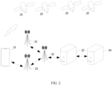
- FIG. 2 is a schematic block diagram of an architecture of a PGNSS system according to an embodiment of this application. As shown in FIG. 2 , the system may include a terminal device 21, data exchange centers 22, a PGNSS server 23, a data source server 24, and GNSS satellites 25.
- the data exchange centers 22 are configured to transmit data.
- the data source server 24 is configured to store a data source, where the data source may be, but is not limited to, precise ephemeris data, broadcast ephemeris data, or an original carrier phase observation quantity.
- the PGNSS server 23 is configured to: obtain the data source stored in the data source server 24, and generate predicted ephemeris data based on the data source.
- the terminal device 21 is configured to: obtain the predicted ephemeris data generated by the PGNSS server 23, and determine a current position and/or a current speed of the terminal device 21 based on the predicted ephemeris data.
- a terminal positioning process based on the PGNSS system includes:
- the PGNSS server 23 After obtaining the data source, the PGNSS server 23 performs modeling based on the data source to obtain a satellite orbit prediction model and a satellite clock error prediction model; then performs satellite orbit prediction based on the satellite orbit prediction model to obtain a predicted orbit; performs satellite clock error prediction based on the satellite clock error prediction model to obtain a predicted clock error; and then fits the predicted orbit and the predicted clock error into broadcast ephemeris parameters and transmits the broadcast ephemeris parameters to the terminal device 21.
- the terminal device 21 may periodically inject the broadcast ephemeris parameters into a GNSS chip, to calculate positions, speeds, and clock errors of visible GNSS satellites by using the GNSS chip and the broadcast ephemeris parameters, and determine the current position and/or the current speed based on the positions, the speeds, and the clock errors of the visible GNSS satellites, a pseudorange, a carrier phase observation quantity, and the like.
- FIG. 3 is a schematic block diagram of a system architecture of an ephemeris prediction solution according to an embodiment of this application.
- the system may include a terminal device 31 and a server 33.
- the terminal device 31 and the server 33 are connected by a network 32.
- the terminal device 31 is a device that has a wireless transceiver function, and may be a handheld terminal device, a vehicle, a vehicle-mounted terminal, an intelligent wearable device, another computing device, or the like.
- the terminal device is a portable terminal device, for example, a mobile phone or a tablet computer, or may be an augmented reality (augmented reality, AR) device, a virtual reality (virtual reality, VR) device, or an ultra-mobile personal computer (ultra-mobile personal computer, UMPC).
- augmented reality augmented reality, AR
- VR virtual reality
- UMPC ultra-mobile personal computer
- FIG. 4 is a schematic structural block diagram of a terminal device 31 according to an embodiment of this application.
- the terminal device 31 may include, but is limited to, a processor 311, a GNSS chip 312, and a memory 313. Both the GNSS chip 312 and the memory 313 are communicatively connected to the processor 311.
- the terminal device 31 further includes a GNSS antenna configured to send and receive a GNSS signal.
- the processor 311 may include one or more processing units.
- the processor 311 may include an application processor (application processor, AP), a modem processor, a controller, a baseband processor, and the like.
- Different processing units may be independent components, or may be integrated into one or more processors.
- the controller may be a nerve center and a command center of the terminal device 31.
- the controller may generate an operation control signal based on an instruction operation code and a time sequence signal, to complete control of instruction fetching and instruction execution.
- the memory 313 may be configured to store computer-executable program code, and the executable program code includes instructions.
- the processor 311 executes various function applications and data processing of the terminal device 31 by running the instructions stored in the memory 313.
- the memory 313 may include a program storage area and a data storage area.
- the program storage area may store an operating system, an application required by at least one function, and the like.
- the data storage area may store data or the like created during use of the terminal device 31. For example, after receiving broadcast ephemeris parameters from a server end, the terminal device 31 stores the broadcast ephemeris parameters in the data storage area, periodically reads the broadcast ephemeris parameters from the data storage area, and injects the broadcast ephemeris parameters into the GNSS chip 312.
- the memory 313 may include a high-speed random access memory, and may further include a non-volatile memory, for example, at least one magnetic disk storage device, a flash memory device, or a universal flash storage (universal flash storage, UFS).
- a non-volatile memory for example, at least one magnetic disk storage device, a flash memory device, or a universal flash storage (universal flash storage, UFS).
- the terminal device 31 may send and receive a GNSS signal and implement GNSS positioning and/or speed setting through the GNSS antenna and the GNSS chip 312.
- the GNSS may include a global positioning system (global positioning system, GPS), a global navigation satellite system (global navigation satellite system, GLONASS), a BeiDou navigation satellite system (BeiDou navigation satellite system, BDS), a quasi-zenith satellite system (quasi-zenith satellite system, QZSS), and/or a satellite based augmentation system (satellite based augmentation system, SBAS).
- a global positioning system global positioning system
- GLONASS global navigation satellite system
- BeiDou navigation satellite system BeiDou navigation satellite system
- BDS BeiDou navigation satellite system
- QZSS quasi-zenith satellite system
- SBAS satellite based augmentation system
- the terminal device 31 may include more or fewer components than those shown in the figure, or some components can be combined, or some components can be split, or a different component arrangement can be used.
- the components shown in the figure may be implemented by hardware, software, or a combination of software and hardware.
- the intelligent wearable device may be a smart band, a smart watch, smart glasses, or the like.
- the terminal device 31 may further include a sensor, a display screen, and the like.
- the sensor may include a photoelectric sensor and a physiological sensor.
- the terminal device 31 may further include a charging management module, a power management module, a battery, a mobile communication module, an audio module, a speaker, a receiver, a microphone, a headset interface, a sensor module, a button, a motor, an indicator, a camera, a display screen, a subscriber identification module (subscriber identification module, SIM) card interface, and the like.
- a charging management module a power management module, a battery
- a mobile communication module an audio module, a speaker, a receiver, a microphone, a headset interface, a sensor module, a button, a motor, an indicator, a camera, a display screen, a subscriber identification module (subscriber identification module, SIM) card interface, and the like.
- SIM subscriber identification module
- the server 32 may include one or more servers. Generally, the server 32 mainly includes a PGNSS server.
- the server 32 is configured to: obtain a data source, perform satellite orbit prediction and satellite clock error prediction based on the data source, convert a predicted orbit and a predicted clock error into specific parameters, and transmit the parameters to the terminal device 31.
- the terminal device 31 is configured to: obtain the predicted orbit and the predicted clock error from the server 32 in a network request manner, calculate positions, speeds, and the like of visible GNSS satellites by using the GNSS chip based on the predicted orbit and the predicted clock error, and then determine a current position and/or a current speed of the terminal device based on the positions, the speeds, and the like of the GNSS satellites.
- Embodiments of this application may be applicable to a navigation positioning and/or speed testing scenario.
- the terminal device 31 is a vehicle-mounted terminal, and the vehicle-mounted terminal performs vehicle positioning and vehicle speed measurement by using the GNSS.
- the terminal device 31 is a mobile phone, and an application program of the mobile phone recommends a commodity to a user by using an LBS.
- Application scenarios are not limited in embodiments of this application.
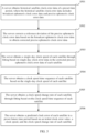
- FIG. 5 is a schematic block diagram of a procedure of a clock error prediction method according to an embodiment of this application. The method is applied to a server, and the procedure may include the following steps.
- Step S501 The server obtains historical satellite clock error data of a preset time period, where the historical satellite clock error data includes broadcast ephemeris clock error data and precise ephemeris clock error data.
- the preset time period may be set according to an actual requirement.
- the preset time period is two days, to be specific, the server obtains historical satellite clock error data of two days.
- a clock error of an atomic clock carried on a GNSS satellite is usually described by using a linear polynomial or a quadratic polynomial.
- a broadcast ephemeris clock error may be shown in the following Formula (1).
- clk n ( t ) is a satellite clock error at a moment t.
- a 0 n is a clock error at an initial moment t 0
- a 1 n is a clock speed at the initial moment t 0
- a 2 n is a clock drift at the initial moment t 0 .
- ⁇ ( t ) is an uncertainty component that changes randomly.
- the precise ephemeris clock error data has higher precision than broadcast ephemeris clock error data, and a predicted clock error with higher precision may be generated based on the precise ephemeris clock error data.
- a precise clock error has a time-varying reference deviation b ( t ) .
- reference deviations b ( t ) of precise ephemeris clock error data from different sources are different.
- the reference deviation b ( t ) affects precision of clock error prediction.
- the precise ephemeris clock error data may be corrected before the precise ephemeris clock error data is used for satellite clock error prediction, and then the corrected precise ephemeris clock error data is used for satellite clock error prediction.
- Step S502 The server corrects a reference deviation of the precise ephemeris clock error data based on the broadcast ephemeris clock error data to obtain corrected precise ephemeris clock error data.
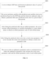
- FIG. 6 is a schematic block diagram of a correction process of a reference deviation of precise ephemeris clock error data.
- the correction process may include the following steps.
- Step S601 The server calculates a difference between a broadcast ephemeris clock error sequence and a precise ephemeris clock error sequence of a same epoch to obtain a difference sequence of each epoch, where the broadcast ephemeris clock error data includes broadcast ephemeris clock error sequences of epochs, and the precise ephemeris clock error data includes precise ephemeris clock error sequences of the epochs.
- GPS broadcast ephemeris clock errors and precise clock errors of an epoch correspond to 32 clock error sequences (that is, 32 satellites) respectively.
- each epoch corresponds to one difference sequence.
- Step S602 The server determines an average value and a standard deviation of each difference sequence.
- Step S603 For each difference sequence, the server removes, from the difference sequence based on the average value and the standard deviation, a difference point that does not meet a preset condition, to obtain a target difference sequence.
- an abnormal difference in the difference sequence may be eliminated in an iterative manner by using 3 sigma. Specifically, for each difference sequence, it is determined, based on the average value and the standard deviation, whether each difference point in the difference sequence satisfies x ⁇ ⁇ ⁇ > 3 , where x is the difference point in the difference sequence, ⁇ is the average value of the difference sequence, and ⁇ is the standard deviation of the difference sequence.
- a next round of abnormal difference elimination process is performed based on the difference sequence after elimination of the difference point.
- the server calculates an average value and a standard deviation of the difference sequence after elimination of the difference point, and determines, based on the average value and the standard deviation, whether each difference point in the difference sequence after elimination of the difference point satisfies x ⁇ ⁇ ⁇ > 3 , and if the difference point satisfies the formula, eliminates the corresponding difference point. In this way, each difference point is determined, to obtain a difference sequence again after the difference point is eliminated.
- the foregoing abnormal difference elimination process is performed iteratively until no difference point is eliminated from a difference sequence, and the difference sequence is the target difference sequence.
- the process returns to the step of determining, based on the average value and the standard deviation, whether each difference point in the difference sequence satisfies x ⁇ ⁇ ⁇ > 3 , until no difference point in the difference sequence satisfies the preset condition, and the difference sequence with no difference point meeting the preset condition is used as the target difference sequence.
- an average value and a standard deviation of the difference sequence are calculated, and it is determined whether each of the 32 difference points satisfies x ⁇ ⁇ ⁇ > 3 .
- the two abnormal difference points are eliminated to obtain a difference sequence after elimination of the difference points.
- the difference sequence after elimination of the difference points herein includes 30 difference points. At this point, the first round of abnormal difference point elimination process is completed.
- a next round of abnormal difference point elimination process is performed.
- an average value and a standard deviation of the difference sequence including 30 difference points are calculated, and it is determined, based on the average value and the standard deviation, whether each of the 30 difference points satisfies x ⁇ ⁇ ⁇ > 3 .
- the difference sequence after elimination of the difference point herein includes 29 difference points.
- a next round of abnormal difference point elimination process is then performed.
- an average value and a standard deviation of the difference sequence including 29 difference points are calculated, and it is determined, based on the average value and the standard deviation, whether each of the 29 difference points satisfies x ⁇ ⁇ ⁇ > 3 .
- the difference sequence after elimination of the difference point herein includes 28 difference points.
- a next round of abnormal difference point elimination process is then performed.
- an average value and a standard deviation of the difference sequence including 28 difference points are calculated, and it is determined, based on the average value and the standard deviation, whether each of the 28 difference points satisfies x ⁇ ⁇ ⁇ > 3 .
- it is assumed that no difference point satisfies x ⁇ ⁇ ⁇ > 3 in other words, there is no difference point to be eliminated, and the difference sequence including 28 difference points is used as the target difference sequence.
- Step S604 The server calculates a reference deviation based on the target difference sequence.
- the reference deviation is calculated by using the following Formula (3).
- Step S605 The server calculates a difference between the precise ephemeris clock error data and the reference deviation to obtain the corrected precise ephemeris clock error data.
- the server may subtract the reference deviation from the precise ephemeris clock error data in satellite clock error data to obtain the corrected precise ephemeris clock error data.
- the precise ephemeris clock error data is corrected based on the broadcast ephemeris clock error data, which can further improve the precision and reliability of satellite clock error prediction.
- Step S503 The server obtains a single-day clock speed of each satellite through fitting based on single-day clock error data in the corrected precise ephemeris clock error data of each satellite.
- the corrected precise ephemeris clock error data includes clock error data of one or more days of each satellite, and single-day fitting is performed on each satellite based on the single-day clock error data of each satellite, to obtain the single-day clock speed.
- the server may first perform coarse difference detection on the single-day clock error data in the corrected precise ephemeris clock error data, to obtain the precise ephemeris clock error data obtained through the coarse difference detection.
- the original clock error time sequence herein refers to the corrected precise ephemeris clock error data.
- the item a 0 refers to a clock error
- the item a 1 refers to a clock speed.
- the coarse difference detection method may be any method.
- the coarse difference detection method may be median detection.
- the server may not perform coarse difference detection on clock error data.
- the coarse difference detection may eliminate a coarse difference from the clock error data, so that precision of subsequent clock error prediction is higher.
- the server uses the precise ephemeris clock error data obtained through coarse difference detection as an observation value, and establishes a linear polynomial model or a quadratic polynomial model for each satellite.
- an observation equation of a satellite is shown in the following Formula (4).
- a 0 indicates the clock error
- a 1 indicates the clock speed
- the server Based on the single-day clock error data of each satellite, the server performs single-day fitting on clock errors by using a least square method, to calculate a clock error model coefficient of each satellite every day.
- a least square method For example, the foregoing Formula (4) is used as an example.
- Single-day fitting is performed on clock errors, to obtain clock error model coefficients a 0 and a 1 of each satellite every day.
- Step S504 The server obtains a clock speed time sequence of each satellite based on the single-day clock speed of each satellite.
- the server may obtain clock error model coefficients a 0 and a 1 of each satellite of a plurality of days based on the satellite clock error data of each satellite every day.
- FIG. 7 shows a clock speed time sequence of some satellites of 235 days.
- Step S505 The server obtains a clock speed change rate of each satellite through fitting based on the clock speed time sequence of each satellite.
- the clock speed time sequence may be fit by using a sliding window.
- the sliding window is used to slide in the clock speed time sequence.
- a predicted clock speed at a next moment is predicted based on a clock speed in the sliding window at a current moment and a fitting result obtained through previous fitting.
- the clock speed to be added to the sliding window may participate in a fitting process of a next clock speed change rate.
- fitting is performed based on the clock speed in the sliding window, a clock speed change rate and a fitting residual of current fitting are obtained.
- a clock speed time sequence of a satellite includes five clock speeds, and the five clock speeds are sequentially b 1 , b 2 , b 3 , b 4 , and b 5 in a time sequence.
- a clock speed value corresponding to t 1 is b 1
- a clock speed value corresponding to t 2 is b 2
- a clock speed value corresponding to t 3 is b 3
- a clock speed value corresponding to t 4 is b 4
- a clock speed value corresponding to t 5 is b 5 .
- clock speeds included in the sliding window are b 1 , b 2 , b 3 , and b 4 .
- a predicted clock speed at t 5 (that is, the next moment) is predicted based on the clock speeds in the sliding window at this time, and the predicted clock speed is B 5 .
- the clock speed to be added to the sliding window is b 5 .
- a difference between the predicted clock speed B 5 and a real clock speed b 5 at the moment t 5 is calculated, and it is determined whether the difference is less than or equal to the first preset threshold.
- clock speeds included in the sliding window are b 1 , b 2 , b 3 , b 4 , and b 5 .
- Fitting is performed based on b 1 , b 2 , b 3 , b 4 , and b 5 in the sliding window at this moment, to obtain a current clock speed change rate and a fitting residual of current fitting.
- the fitting residual is less than or equal to a second preset threshold. If the fitting residual is less than or equal to the second preset threshold, the current clock speed change rate is used as a clock speed change rate of the satellite. In contrast, if the fitting residual is greater than the second preset threshold, it is considered that a coarse difference or the item a 1 jumps, and after the sliding window is reset, the sliding window continues to slide forward. In the sliding process, fitting and determining are performed according to the foregoing process until the clock speed time sequence is traversed or the fitting residual is less than or equal to the second preset threshold.
- the sliding window is reset and the sliding window continues to slide forward until the clock speed time sequence is traversed or the fitting residual is less than or equal to the second preset threshold.
- the first preset threshold, the second preset threshold, and the preset quantity may be set according to an actual requirement, which is not limited herein.
- a size of the sliding window is 5, in other words, a quantity of clock speeds that can be accommodated in the sliding window is preset to 5.
- a quantity of clock speeds that can be accommodated in the sliding window is preset to 5.
- the preset quantity is 3, and each time the quantity of clock speeds in the sliding window is greater than or equal to 3, fitting and prediction start to be performed based on the clock speeds in the sliding window.
- a clock speed time sequence of a satellite includes 100 clock speeds, to be specific, clock speed values corresponding to moments t 1 , t 2 , t 3 , ..., and t 100 are b 1 , b 2 , b 3 , ..., and b 100 respectively.
- the quantity of clock speeds in the sliding window is 0, in other words, there is no clock speed in the sliding window.
- the sliding window continues to slide forward, and it is determined whether the quantity of clock speeds included in the sliding window is greater than or equal to 3.
- the sliding window includes a total of five clock speed values, namely, b 5 , b 6 , b 7 , b 8 , and b 9 .
- a predicted clock speed B10 at a next moment is predicted based on the five clock speed values, namely, b 5 , b 6 , b 7 , b 8 , and b9.
- a difference between the predicted clock speed B 10 and a real clock speed b 10 is calculated, and it is determined whether the difference is less than or equal to the first preset threshold. If the difference is less than or equal to the first preset threshold, a real clock speed b 11 at a next moment is added to the sliding window. In this case, a maximum quantity of clock speeds in the sliding window is 5. Therefore, one clock speed needs to be removed, and the clock speed b 10 at the next time needs to be added to the sliding window.
- the clock speed values included in the sliding window are b 6 , b 7 , b 8 , b 9 , and b 10 , and fitting is performed based on the clock speed values in the sliding window at this moment to obtain a clock speed change rate and fitting residual. Then, it is further determined whether a fitting residual of current fitting is less than or equal to the second preset threshold.
- the sliding window is reset.
- Resetting the sliding window means resetting a quantity of clock speeds in the sliding window, to be specific, the reset sliding window does not include any clock speed.
- the sliding window continues to slide forward based on a sliding step size, and in a sliding process, it continues to be determined whether the quantity of clock speeds in the sliding window is greater than or equal to 3.
- a predicted clock speed at a next moment is predicted based on the clock speeds in the sliding window at the moment, a difference between the predicted clock speed and the real clock speed is calculated, and the difference is compared with the first preset threshold. This process is repeated until the clock speed time sequence is traversed, or a fitting residual of a clock speed change rate fitting process is less than or equal to the second preset threshold.
- the clock speed change rate is fitted based on the clock speed time sequence, and abnormality detection is performed, by using the sliding window, on the clock speeds and the fitting residual that are for fitting prediction, which improves accuracy of the clock speed change rate, and further improves precision and reliability of clock error prediction of a candidate satellite.
- an existing clock speed change rate fitting manner may be used.
- Step S506 The server obtains a predicted clock error of each satellite in a preset future time period based on an initial clock error value, a clock speed, and the clock speed change rate of each satellite.
- the server After fitting the clock speed change rate based on the clock speed time sequence of each satellite, the server performs satellite clock error prediction based on the satellite clock error a 0 (that is, the initial clock error value) of reference time, the clock speeds obtained through fitting, and the clock speed change rate, to obtain the predicted clock error of each satellite in the preset future time period.
- satellite clock error a 0 that is, the initial clock error value
- an improved satellite clock error prediction procedure provided in embodiments of this application can further improve precision and reliability of satellite clock error prediction.
- An ephemeris prediction procedure includes a clock error prediction procedure and an orbit prediction procedure.
- the ephemeris prediction procedure is described below.
- FIG. 8 is a schematic flowchart of an ephemeris prediction method according to an embodiment of this application. As shown in FIG. 8 , the procedure may include the following steps.
- Step S801 A server obtains EOP data and historical ephemeris data of a preset time period.
- the historical ephemeris data may include precise ephemeris data, may include real-time broadcast ephemeris data, or may include an original carrier phase observation quantity.
- the historical ephemeris data may be a data source in a PGNSS.
- the historical ephemeris data includes satellite orbit data and satellite clock error data.
- the satellite orbit data includes satellite position information of each satellite at each moment
- the satellite clock error data includes satellite clock error information of each satellite at each moment.
- the satellite orbit data and earth orientation parameter (Earth Orientation Parameter, EOP) data may be used for satellite orbit prediction
- the satellite clock error data may be used for satellite clock error prediction.
- the satellite clock error data may be the historical satellite clock error data in FIG. 5 above.
- the precise ephemeris data may include a precise orbit product and a precise clock error product.
- the precise orbit product and an EOP file are used for satellite orbit prediction, and the precise clock error product is used for satellite clock error prediction.
- the server may download the precise orbit product and the precise clock error product from a file transfer protocol (File Transfer Protocol, FTP) server of an international GNSS service (International GNSS Service, IGS), and download the EOP file from a server of an international earth rotation service (International Earth Rotation Service, IERS).
- FTP File Transfer Protocol
- IGS International GNSS Service
- IERS International Earth Rotation Service
- the preset time period may be set according to an actual requirement.
- the preset time period is two days, to be specific, the server obtains historical ephemeris data of two days.
- the server may obtain satellite orbit data of one or more days, and perform satellite orbit prediction based on the satellite orbit data of one or more days.
- optimal fitting duration may be set to two days, to estimate a satellite orbit dynamic parameter more accurately, which improves precision of satellite orbit prediction.
- the server obtains satellite orbit data of two consecutive days, and uses the satellite orbit data of the two consecutive days to perform satellite orbit prediction. Compared with using satellite orbit data of one day or at least three days to perform satellite orbit prediction, the former has higher precision of satellite orbit prediction.
- Step S802 The server performs satellite orbit prediction and satellite clock error prediction based on the EOP data and the historical ephemeris data, to obtain a predicted orbit and a predicted clock error in a preset future time period.
- the server may use the EOP data and the satellite orbit data in the historical ephemeris data to perform satellite orbit prediction, and use the satellite clock error data in the historical ephemeris data to perform satellite clock error prediction.
- the preset future time period may be set according to an actual requirement.
- the preset future time period may be 7 to 28 days, that is, the server may predict a satellite orbit and a satellite clock error in the future 7 to 28 days.
- a satellite orbit prediction procedure and a satellite clock error prediction procedure are separately described below.
- an embodiment of this application provides an improved satellite orbit prediction procedure.
- the satellite orbit prediction procedure different solar radiation pressure models may be used for different types of satellites.
- the satellite orbit prediction procedure refer to a schematic block diagram of a satellite orbit prediction procedure shown in FIG. 9 . As shown in FIG. 9 , the procedure may include the following steps.
- Step S901 The server converts, based on the EOP data, satellite position information in an earth-fixed system into satellite position information in an inertial system.
- the satellite orbit data includes the satellite position information in the earth-fixed system.
- the satellite orbit data may be a precise orbit product.
- the server may perform satellite orbit prediction based on satellite orbit data of two consecutive days, in other words, optimal fitting estimation duration is set to two days.
- Step S902 The server determines, based on a correspondence between a satellite type and a solar radiation pressure model, a target solar radiation pressure model corresponding to each satellite in the satellite orbit data.
- a solar radiation pressure model used by each type of satellite is determined in advance.
- Table 1 Satellite type Solar radiation pressure model GPS satellite or GLONASS satellite ECOM5 parameter model Galileo (Galileo) satellite Box-wing initial light pressure model and ECOM5 parameter model BeiDou GEO satellite Initial light pressure model, ECOM5 parameter model, and periodic empirical force parameter BeiDou IGSO satellite or BeiDou MEO satellite ECOM5 parameter model QZSS satellite Initial light pressure model and ECOM5 parameter model
- a target solar radiation pressure model of the satellite is an ECOM5 parameter model.
- a target light pressure model of the satellite is an initial light pressure model and an ECOM5 parameter model.
- the satellite orbit data includes three-dimensional position information of each satellite at each moment, and the satellite orbit data includes identification information of each satellite.
- the identification information may be, for example, a satellite number.
- the server determines a satellite type of each satellite in the satellite orbit data based on the identification information such as the satellite number in the satellite orbit data, and then determines, based on the satellite type of each satellite and the preset correspondence between a satellite type and a solar radiation pressure model, a target solar radiation pressure model corresponding to each satellite.
- Step S903 The server establishes a satellite motion equation and a variational equation of each satellite based on the target solar radiation pressure model of each satellite and the satellite position information in the inertial system.
- the server establishes the satellite motion equation and the variational equation of the satellite based on the target solar radiation pressure model of the satellite and the satellite position information of the satellite in the inertial system.
- Step S904 The server obtains, based on the motion equation and the variational equation of each satellite, a reference orbit position, a speed, and a state transfer matrix of each satellite at each moment in a numerical integration manner.
- the server In a process of obtaining the reference orbit position, the speed, and the state transfer matrix at each moment in the numerical integral manner, the server needs to obtain a reference orbit position, a speed, and a state transfer matrix at a current moment based on information such as a position, a speed, and a state transfer matrix of a reference orbit at a previous moment.
- Step S905 The server obtains, based on the satellite orbit data, the reference orbit position, and the state transfer matrix, satellite orbit status parameters of each satellite at a reference moment by using a least square integral solution.
- the satellite orbit status parameters at the reference moment may include, but are not limited to, a satellite position, a speed, a dynamic model parameter, and an empirical force parameter at the reference moment.
- Step S906 The server obtains a satellite orbit in a preset future time period in a numerical integral manner based on the satellite orbit status parameters at the reference moment and a satellite dynamic model.
- the obtained satellite orbit in the preset future time period is a satellite orbit in the inertial system.
- Step S907 The server converts, based on the EOP data, a satellite orbit in the preset future time period in the inertial system into the earth-fixed system, to obtain a predicted orbit in the preset future time period.
- the server may convert, based on an EOP prediction value in the EOP data, the satellite orbit of the inertial system obtained in step S906 into the earth-fixed system.
- an existing satellite orbit prediction manner may be used to perform satellite orbit prediction.
- the server may use the improved satellite orbit prediction procedure provided in embodiments of this application, or may use an existing satellite orbit prediction procedure.
- the server may use the improved satellite clock error prediction procedure provided in embodiments of this application, or may use an existing satellite clock error prediction procedure.
- the improved satellite clock error prediction procedure provided in embodiments of this application is shown in FIG. 5 .
- FIG. 5 For a specific description, refer to related content in FIG. 5 above. Details are not described herein again.
- Step S803 After fitting the predicted orbit into an orbital parameter, the server encodes orbital parameters of satellites belonging to a same orbital plane to obtain an orbital parameter code of each orbital plane.
- Step S804 After fitting the predicted clock error into a clock error parameter, the server encodes the clock error parameter to obtain a clock error parameter code.
- the server encodes the clock error parameter to obtain the clock error parameter code.
- the server may perform segment fitting on the predicted orbit by using a group of Kepler orbital parameters, to obtain an orbital parameter of each segment of the predicted orbit.
- a process in which the server fits the predicted orbit into the orbital parameter may be as follows: First, the server performs equal-interval sampling on the predicted orbit to obtain the satellite position of each sampling point.
- a sampling interval may be set according to an actual requirement, for example, the sampling interval may be 5 minutes. To be specific, the server performs sampling once every 5 minutes.
- the initial sampling point is T 0
- a predicted orbit position corresponding to a moment T 0 is (x 0 , y 0 , z 0 )
- a next sampling point is T 1
- T 1 T 0 + 5
- a predicted orbit position corresponding to a moment T1 is (x1, y1, z1), and so on, until sampling is completed.
- a plurality of sampling points and a predicted orbit position corresponding to each sampling point are obtained.
- the server segments the plurality of sampling points according to time, to obtain a segmentation result. For example, segmentation is performed by using four hours, and a segmentation result obtained through sampling at an interval of five minutes is shown in Table 2.
- Table 2 Time X-coordinate value Y-coordinate value Z-coordinate value T 0 X 0 Y 0 Z 0 T 1 X 1 Y 1 Z 1 ... ... ... ... T 48 X 48 Y 48 Z48
- the predicted orbit position corresponding to the moment T 0 is (x 0 , y 0 , z 0 ), and a predicted orbit position corresponding to a moment T 48 is (x 48 , y 48 , z 48 ).
- a 16-parameter broadcast ephemeris model or an 18-parameter broadcast ephemeris model may be used, and fitting is performed on each segment of the predicted orbit to obtain a broadcast ephemeris parameter corresponding to each segment of the predicted orbit.
- a fitting algorithm such as a least square method may be used in a fitting process.
- the 16-parameter broadcast ephemeris model may be shown in Table 3 below.
- the server may directly send the orbital parameter to the terminal device.
- the server may directly send the orbital parameter to the terminal device.
- there is a large amount of data of orbital ephemeris parameters and direct sending of the orbital ephemeris parameters to the terminal device causes a large amount of parameter broadcast data.
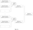
- this embodiment of this application provides a manner of broadcasting ephemeris parameters based on an orbital plane.
- orbital ephemeris parameters belonging to a same orbital plane are encoded, to obtain an orbital ephemeris parameter code of each orbital plane.
- Orbital ephemeris parameters of satellites on a same orbital plane have strong consistency, and therefore the orbital ephemeris parameters of the same orbital plane may be encoded.
- FIG. 10 is a schematic diagram of a manner of encoding orbital ephemeris parameters based on an orbital plane.
- an ephemeris parameter code 1 of the orbital plane 1 is obtained.
- an ephemeris parameter code N of the orbital plane N is obtained.
- the original broadcast ephemeris parameter refers to an ephemeris parameter obtained by performing segment fitting on the predicted orbit and the predicted clock error by the server by using a Kepler orbital parameter.
- the server After obtaining the ephemeris parameter code 1, ..., and the ephemeris parameter code N, the server sends the ephemeris parameter code 1, ..., and the ephemeris parameter code N to the terminal device, instead of sending the original broadcast ephemeris parameter to the terminal device.
- an amount of data of ephemeris parameter broadcast can be reduced.
- Table 4 below shows a comparison between an amount of data broadcast based on an original broadcast ephemeris parameter and an amount of data broadcast based on an orbital plane.
- Table 4 Broadcast mode Weekly amount of data of a single constellation/kb Broadcast based on an original broadcast ephemeris parameter 54.35 Broadcast based on an orbital plane 44.92
- an original ephemeris parameter of one satellite may be normally encoded first, and then ephemeris parameters of other satellites on the same orbital plane are incrementally encoded based on the normally encoded ephemeris parameter of the satellite, to finally obtain the ephemeris parameter code of the orbital plane.
- the orbital plane 1 includes three satellites.
- One of the three satellites is selected as a target satellite, and an original broadcast ephemeris parameter of the target satellite is normally encoded, to obtain an ephemeris parameter code of the target satellite.
- an original broadcast ephemeris parameter of the target satellite is normally encoded, to obtain an ephemeris parameter code of the target satellite.
- incremental encoding is performed based on the ephemeris parameter code of the target satellite.
- Step S805 The server sends an ephemeris parameter code to the terminal device, where the ephemeris parameter code includes the clock error parameter code and the orbital parameter code of each orbital plane.
- the terminal device may obtain the predicted orbit and the predicted clock error from the server in a network request manner.
- the server may send the clock error parameter code and the orbital parameter code of each orbital plane to the terminal device in response to the request.
- the terminal device After obtaining the ephemeris parameter code, the terminal device decodes the orbital parameter code to obtain an orbital ephemeris parameter of each satellite, calculates positions, speeds, and clock errors of all visible GNSS satellites based on the broadcast ephemeris parameter and the clock error parameter, and finally determines a current position and/or a current speed based on the positions and speeds of the visible GNSS satellites, an observation quantity, and the like.
- an orbital ephemeris parameter is encoded based on an orbital plane, to obtain an orbital ephemeris parameter code of each orbital plane, so that an amount of data of parameter broadcast can be effectively reduced.
- an embodiment of this application further provides an improved satellite orbit prediction procedure, to improve precision of satellite orbit prediction.
- an embodiment of this application further provides an improved satellite clock error prediction procedure, to improve precision and reliability of satellite clock error prediction.
- an embodiment of this application provides another ephemeris prediction solution.
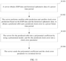
- FIG. 11 is another schematic block diagram of a procedure of an ephemeris prediction method according to an embodiment of this application.
- the ephemeris prediction method may include the following steps.
- Step S1101 A server obtains EOP data and historical ephemeris data of a preset time period.
- Step S1102 The server performs satellite orbit prediction and satellite clock error prediction based on the EOP data and the historical ephemeris data, to obtain a predicted orbit and a predicted clock error in a preset future time period.
- step S1101 and step S1102 refer to the foregoing step S801 and step S802. Details are not described herein again.
- the server may perform satellite orbit prediction in an existing satellite orbit prediction manner, or may perform satellite orbit prediction in an improved satellite orbit prediction manner provided in embodiments of this application.
- the server may perform satellite clock error prediction in an existing satellite clock error prediction manner, or may perform clock error prediction in an improved satellite clock error prediction manner provided in embodiments of this application.
- the improved satellite orbit prediction procedure refer to FIG. 9 and related content.
- the improved satellite clock error prediction procedure refer to FIG. 5 and related content. Details are not described herein again.
- Step S1103 The server fits the predicted orbit into a polynomial coefficient by using a polynomial model, and fits the predicted clock error into a clock error parameter.
- the polynomial model includes a basis function and a coefficient of the basis function.
- n a basis function order.
- a GNSS satellite position may be represented by using a basis function.
- x ( t ), y ( t ), and z ( t ) represent three-dimensional satellite positions.
- a process in which the server fits the predicted orbit into the polynomial coefficient by using a polynomial may include: First, the server performs equal-interval sampling and segmentation on the predicted orbit to obtain a segmentation result. For descriptions of sampling and segmentation, refer to related content in step S503. Details are not described herein again.
- the server uses a basis function to represent a satellite position at each sampling point, to determine a basis function coefficient corresponding to the satellite position at each sampling point.
- a segmentation result of a segment of a predicted orbit is shown in Table 2, the foregoing Formula (6) is used to separately represent predicted orbit positions corresponding to moments T 0 , T 1 , ..., and T 48 , and based on X-coordinate values, Y-coordinate values, and Z-coordinate values corresponding to each moment, basis function coefficients corresponding to the moments T 0 , T 1 , ..., and T 48 are determined.
- the server fits the predicted clock error into the clock error parameter.
- Step S1104 The server sends the polynomial coefficient and the clock error parameter to a terminal device.
- the terminal device may obtain the predicted orbit and the predicted clock error from the server in a network request manner.
- the server may send the polynomial coefficient and the clock error parameter to the terminal device in response to the request.
- the terminal device receives the polynomial coefficient and the clock error parameter from a generator. After obtaining the polynomial coefficient, the terminal device may calculate a satellite clock error of a visible GNSS satellite based on the clock error parameter, calculate a position of the GNSS satellite based on the basis function and the polynomial coefficient, and calculate a speed of the GNSS satellite based on the polynomial coefficient and a basis function derivative.
- a polynomial model is used to fit a predicted orbit into a polynomial coefficient, so that an operation amount, a time consumed for operations, and power consumption of a GNSS chip in a positioning process of the terminal device can be reduced.
- the terminal device calculates positions and speeds of all visible GNSS satellites based on the broadcast ephemeris parameter.
- a process in which the terminal device calculates a position and a speed of a single GNSS satellite based on the broadcast ephemeris parameter involves many complex floating-point operations. As a result, an operation amount is large, and a large quantity of processor resources are occupied.
- a quantity of visible GNSS satellites in each current positioning epoch is up to 50 or more.
- the operation amount is larger. For example, it is assumed that the terminal device performs positioning once per second, and the terminal device needs to perform more than 50 position resolving processes and more than 50 speed resolving processes for GNSS satellites per second. Therefore, the operation amount is extremely large, and power consumption is high.
- the terminal device calculates the positions and speeds of the GNSS satellites based on the broadcast ephemeris parameter, an operation amount is large, a time consumed for operations is long, and power consumption of the GNSS chip is high.
- the predicted orbit is segmented and fitted into a polynomial coefficient by using a polynomial model.
- the terminal device may calculate a position of a GNSS satellite based on only the polynomial coefficient and the basis function, and may calculate a speed of the satellite based on the polynomial coefficient and the basis function derivative.
- a small quantity of floating-point operations are involved, so that an operation amount is reduced, a time consumed for calculation is reduced, and power consumption of the GNSS chip is reduced.
- fitting duration of each group of broadcast ephemeris parameters is usually four hours.
- the predicted orbit is segmented and fitted by using the polynomial model.
- n 18
- a validity time period of each group of parameters may be up to 12 hours. This means that a lower parameter update frequency may be used for the GNSS chip.
- a polynomial model is used to fit a predicted orbit into a polynomial coefficient, so that an operation amount in a positioning process of a terminal device is effectively reduced, to reduce power consumption in a GNSS positioning process.
- an embodiment of this application further provides an improved satellite orbit prediction procedure, to improve precision of satellite orbit prediction.
- an embodiment of this application further provides an improved satellite clock error prediction procedure, to improve precision and reliability of satellite clock error prediction.
- sequence numbers of the steps do not mean an execution sequence in the foregoing embodiments.
- the execution sequence of the processes should be determined based on functions and internal logic of the processes, and should not constitute any limitation on the implementation processes of embodiments of this application.
- each functional module may be obtained through division based on the foregoing method examples.
- each functional module may be obtained through division based on each corresponding function, or two or more functions may be integrated into one processing module.
- the integrated module may be implemented in a form of hardware, or may be implemented in a form of a software functional module.
- module division is an example, and is merely logical function division. In an actual implementation, there may be another division manner. An example in which each functional module is obtained through division based on each corresponding function is used below for description.
- FIG. 12 is a schematic block diagram of a clock error prediction apparatus according to an embodiment of this application.
- the apparatus may be used in a server, and the apparatus may include:
- the reference deviation correction module is specifically configured to:
- the reference deviation correction module is specifically configured to:
- the reference deviation correction module is specifically configured to:
- the single-day clock speed fitting module is specifically configured to:
- the clock speed change rate fitting module is specifically configured to:
- the terminal device may include a memory, a processor, and a computer program that is stored in the memory and that can be run on the processor.
- the processor When executing the computer program, the processor implements the method according to any one of the method embodiments on the side of the terminal device.
- An embodiment of this application provides a server, including a memory, a processor, and a computer program that is stored in the memory and that can be run on the processor.
- the processor executes the computer program, implements the method according to any one of the method embodiments on the side of the server.
- An embodiment of this application further provides an ephemeris prediction system.
- the system includes a server and a terminal device.
- the server is configured to implement the method according to any one of the embodiments on the side of the server.
- the terminal device is configured to implement the method according to any one of the foregoing method embodiments on the side of terminal device.
- An embodiment of this application further provides a computer-readable storage medium.
- the computer-readable storage medium stores a computer program.
- steps in the foregoing method embodiments can be implemented.
- An embodiment of this application provides a computer program product.
- the computer program product runs on an electronic device
- the electronic device is enabled to implement the steps in the foregoing method embodiments when executing the computer program product.
- the electronic device may be a server or a terminal device.
- An embodiment of this application further provides a chip system.
- the chip system includes a processor, the processor is coupled to a memory, and the processor executes a computer program stored in the memory, to implement the method in the foregoing method embodiments.
- the chip system may be a single chip or a chip module including a plurality of chips.
Landscapes
- Engineering & Computer Science (AREA)
- Radar, Positioning & Navigation (AREA)
- Remote Sensing (AREA)
- Signal Processing (AREA)
- Computer Networks & Wireless Communication (AREA)
- Physics & Mathematics (AREA)
- General Physics & Mathematics (AREA)
- Power Engineering (AREA)
- Position Fixing By Use Of Radio Waves (AREA)
Applications Claiming Priority (2)
| Application Number | Priority Date | Filing Date | Title |
|---|---|---|---|
| CN202110099422.9A CN114791614B (zh) | 2021-01-25 | 2021-01-25 | 钟差预报方法和装置 |
| PCT/CN2021/140946 WO2022156480A1 (zh) | 2021-01-25 | 2021-12-23 | 钟差预报方法和装置 |
Publications (2)
| Publication Number | Publication Date |
|---|---|
| EP4258024A1 true EP4258024A1 (de) | 2023-10-11 |
| EP4258024A4 EP4258024A4 (de) | 2024-06-19 |
Family
ID=82460183
Family Applications (1)
| Application Number | Title | Priority Date | Filing Date |
|---|---|---|---|
| EP21920854.3A Pending EP4258024A4 (de) | 2021-01-25 | 2021-12-23 | Taktfehlervorhersageverfahren und -vorrichtung |
Country Status (4)
| Country | Link |
|---|---|
| US (1) | US20240151857A1 (de) |
| EP (1) | EP4258024A4 (de) |
| CN (1) | CN114791614B (de) |
| WO (1) | WO2022156480A1 (de) |
Cited By (1)
| Publication number | Priority date | Publication date | Assignee | Title |
|---|---|---|---|---|
| CN117630986A (zh) * | 2023-12-05 | 2024-03-01 | 中国人民解放军火箭军工程大学 | 一种基于arima与灰色预报模型的顾及随机项的gps卫星钟差预报方法 |
Families Citing this family (15)
| Publication number | Priority date | Publication date | Assignee | Title |
|---|---|---|---|---|
| CN115733489B (zh) * | 2022-11-25 | 2024-01-05 | 中科启迪光电子科技(广州)有限公司 | 一种芯片原子钟驯服方法、装置和系统 |
| CN115792978B (zh) * | 2023-02-17 | 2023-04-28 | 中国科学院国家授时中心 | 一种基于相对论效应的低轨卫星钟差预报方法 |
| CN116520376B (zh) * | 2023-07-05 | 2023-09-08 | 中国科学院空天信息创新研究院 | 一种钟辅助下的高轨北斗接收机定位解算方法 |
| CN116931037B (zh) * | 2023-09-15 | 2023-12-22 | 中国科学院国家空间科学中心 | 一种掩星探测的数据校正方法、装置及设备 |
| CN117092664B (zh) * | 2023-10-17 | 2024-01-09 | 青岛杰瑞自动化有限公司 | 一种基于授时系统的定位抗干扰方法及系统、电子设备 |
| CN117471502B (zh) * | 2023-10-31 | 2024-04-02 | 北京华云星地通科技有限公司 | 一种定位源参数异常检测和修正方法、系统及电子设备 |
| CN117761748B (zh) * | 2023-12-25 | 2024-09-27 | 河南芯港半导体有限公司 | 一种gnss精密钟差数据的监测方法及装置 |
| CN118938267B (zh) * | 2024-07-23 | 2025-04-25 | 广东工业大学 | 一种基于频域信息增强的北斗卫星星历预测方法 |
| CN118549955B (zh) | 2024-07-29 | 2024-09-27 | 广东工业大学 | 一种基于波浪式并行网络的北斗卫星星历预测方法及系统 |
| CN118604862B (zh) * | 2024-07-31 | 2024-11-29 | 深圳市安则为科技有限公司 | 一种提高gnss定位精度的方法、系统及定位终端 |
| CN119105050B (zh) * | 2024-09-02 | 2025-09-23 | 哈尔滨工程大学 | 一种基于vmd-lstm模型的卫星实时钟差预报方法 |
| CN119471737A (zh) * | 2024-11-08 | 2025-02-18 | 中国矿业大学 | 一种基于状态空间表示的gnss精密卫星钟差改正数计算方法 |
| CN120044553B (zh) * | 2025-02-24 | 2025-12-05 | 中国人民解放军网络空间部队信息工程大学 | 低轨卫星星载gnss观测量完好性监测方法及系统 |
| CN120150796B (zh) * | 2025-03-13 | 2025-12-02 | 北京航天飞行控制中心 | 基于星间链路的卫星钟差确定方法及其装置、电子设备 |
| CN120491124B (zh) * | 2025-05-28 | 2026-01-02 | 中国科学院上海天文台 | 基于bds-3导航电文sisre精度提升的低轨卫星定轨方法和系统 |
Family Cites Families (14)
| Publication number | Priority date | Publication date | Assignee | Title |
|---|---|---|---|---|
| US7839324B2 (en) * | 2007-02-12 | 2010-11-23 | Sirf Technology, Inc. | Efficient ephemeris coding |
| US8260540B2 (en) * | 2007-04-27 | 2012-09-04 | Sirf Technology, Inc. | Systems and methods of communication in an assisted navigation system |
| US10185035B2 (en) * | 2014-12-30 | 2019-01-22 | Mediatek Inc. | Satellite-based positioning method and associated apparatus |
| CN105182374B (zh) * | 2015-08-28 | 2018-02-13 | 山东鼎成卫星导航定位技术有限公司 | 一种基于北斗短报文精密轨道和钟差播发的方法及系统 |
| CN109387859B (zh) * | 2017-08-14 | 2023-05-30 | 千寻位置网络有限公司 | 基于地面跟踪站产生长期卫星轨道和钟差的方法和装置 |
| CN107748372A (zh) * | 2017-09-15 | 2018-03-02 | 千寻位置网络有限公司 | 基于gnss高精度系统的卫星钟差实时估计系统及方法 |
| CN108107455A (zh) * | 2017-10-30 | 2018-06-01 | 千寻位置网络(浙江)有限公司 | 一种基于相位跳变的卫星钟差实时预报方法 |
| CN108415050B (zh) * | 2018-06-04 | 2020-05-26 | 北京未来导航科技有限公司 | 一种基于低轨星座导航增强系统的ppp-rtk定位方法 |
| CN110058287B (zh) * | 2019-05-16 | 2022-03-15 | 北京合众思壮科技股份有限公司 | 一种低轨卫星定轨方法、装置及系统 |
| CN110376620B (zh) * | 2019-07-24 | 2022-03-04 | 广州中海达卫星导航技术股份有限公司 | 实时钟差预报方法、装置和计算机设备 |
| CN110376621B (zh) * | 2019-08-15 | 2020-06-09 | 北京航天宏图信息技术股份有限公司 | 一种基于北斗三号B2b信号的卫星定位方法及装置 |
| CN111413719B (zh) * | 2020-03-21 | 2022-07-15 | 哈尔滨工程大学 | 一种基于神经网络的北斗实时精密时钟预测方法 |
| CN111580132B (zh) * | 2020-05-08 | 2022-07-12 | 中国科学院国家授时中心 | 基于时间实验室增强信息的北斗局域精密时间传递方法 |
| CN111766615A (zh) * | 2020-06-15 | 2020-10-13 | 中国人民解放军61081部队 | 基于igs rts数据的站间实时时间传递方法 |
-
2021
- 2021-01-25 CN CN202110099422.9A patent/CN114791614B/zh active Active
- 2021-12-23 WO PCT/CN2021/140946 patent/WO2022156480A1/zh not_active Ceased
- 2021-12-23 EP EP21920854.3A patent/EP4258024A4/de active Pending
- 2021-12-23 US US18/262,596 patent/US20240151857A1/en active Pending
Cited By (1)
| Publication number | Priority date | Publication date | Assignee | Title |
|---|---|---|---|---|
| CN117630986A (zh) * | 2023-12-05 | 2024-03-01 | 中国人民解放军火箭军工程大学 | 一种基于arima与灰色预报模型的顾及随机项的gps卫星钟差预报方法 |
Also Published As
| Publication number | Publication date |
|---|---|
| US20240151857A1 (en) | 2024-05-09 |
| CN114791614B (zh) | 2025-07-04 |
| WO2022156480A1 (zh) | 2022-07-28 |
| EP4258024A4 (de) | 2024-06-19 |
| CN114791614A (zh) | 2022-07-26 |
Similar Documents
| Publication | Publication Date | Title |
|---|---|---|
| EP4258024A1 (de) | Taktfehlervorhersageverfahren und -vorrichtung | |
| CN114791613B (zh) | 星历预报方法和装置 | |
| CN111045034B (zh) | 基于广播星历的gnss多系统实时精密时间传递方法及系统 | |
| EP2673658B1 (de) | Verfahren und system zur bestimmung von taktkorrekturen | |
| EP2567256B1 (de) | Verfahren und vorrichtung für schnelles ttff | |
| CN117388881B (zh) | 一种低轨卫星的星载原子钟向UTC(k)的溯源方法及系统 | |
| CN115308779B (zh) | 星历预报方法和星历预报装置 | |
| CN113325446B (zh) | 一种多模共频gnss载波相位时间传递方法及系统 | |
| CN112285749B (zh) | 全球导航卫星系统原始观测数据处理方法、装置及存储介质 | |
| CN111123331A (zh) | 一种北斗导航伪距监测方法及系统 | |
| CN112505735A (zh) | 对终端进行定位的方法、装置和存储介质 | |
| CN120703791A (zh) | 一种北斗PPP-B2b定位补偿方法及系统 | |
| Anghileri et al. | Reduced navigation data for a fast first fix | |
| CN112540389A (zh) | 一种利用卫星历书的时间同步方法和装置 | |
| CN117368946B (zh) | 基于多基准站实时数据流的卫星广播星历综合方法和系统 | |
| CN114252898B (zh) | 位移监测方法、装置、系统及电子设备 | |
| CN117075153A (zh) | 广播星历异常确定方法、装置、电子设备及存储介质 | |
| CN114966788B (zh) | 一种顾及大气残余误差的ppp-rtk定位方法及装置 | |
| CN117538918A (zh) | 一种对卫星导航定位技术中基准站数据延迟的补偿方法 | |
| CN112415547B (zh) | 卫星信号的周跳计算方法及装置 | |
| CN116893433B (zh) | 一种实现跟踪站观测值预测的方法及装置 | |
| JP2022097435A (ja) | 基準受信機を用いたロービング受信機の時間非依存位置決定 | |
| CN111538045A (zh) | 一种星载导航接收机在轨精度预先评估方法 | |
| CN119758387B (zh) | 卫星钟差的确定方法及装置、程序产品、存储介质 | |
| HK40037485B (en) | Method and apparatus for processing raw observation data of global navigation satellite system, and storage medium |
Legal Events
| Date | Code | Title | Description |
|---|---|---|---|
| STAA | Information on the status of an ep patent application or granted ep patent |
Free format text: STATUS: THE INTERNATIONAL PUBLICATION HAS BEEN MADE |
|
| PUAI | Public reference made under article 153(3) epc to a published international application that has entered the european phase |
Free format text: ORIGINAL CODE: 0009012 |
|
| STAA | Information on the status of an ep patent application or granted ep patent |
Free format text: STATUS: REQUEST FOR EXAMINATION WAS MADE |
|
| 17P | Request for examination filed |
Effective date: 20230706 |
|
| AK | Designated contracting states |
Kind code of ref document: A1 Designated state(s): AL AT BE BG CH CY CZ DE DK EE ES FI FR GB GR HR HU IE IS IT LI LT LU LV MC MK MT NL NO PL PT RO RS SE SI SK SM TR |
|
| DAV | Request for validation of the european patent (deleted) | ||
| DAX | Request for extension of the european patent (deleted) | ||
| REG | Reference to a national code |
Ref country code: DE Ref legal event code: R079 Free format text: PREVIOUS MAIN CLASS: G01S0019370000 Ipc: G01S0019070000 |
|
| A4 | Supplementary search report drawn up and despatched |
Effective date: 20240516 |
|
| RIC1 | Information provided on ipc code assigned before grant |
Ipc: G01S 19/27 20100101ALN20240511BHEP Ipc: G01S 19/07 20100101AFI20240511BHEP |
|
| STAA | Information on the status of an ep patent application or granted ep patent |
Free format text: STATUS: EXAMINATION IS IN PROGRESS |
|
| 17Q | First examination report despatched |
Effective date: 20260225 |