EP4258306A1 - Schaltsystem - Google Patents
Schaltsystem Download PDFInfo
- Publication number
- EP4258306A1 EP4258306A1 EP23305507.8A EP23305507A EP4258306A1 EP 4258306 A1 EP4258306 A1 EP 4258306A1 EP 23305507 A EP23305507 A EP 23305507A EP 4258306 A1 EP4258306 A1 EP 4258306A1
- Authority
- EP
- European Patent Office
- Prior art keywords
- contact area
- contact
- arc
- bracket
- main
- Prior art date
- Legal status (The legal status is an assumption and is not a legal conclusion. Google has not performed a legal analysis and makes no representation as to the accuracy of the status listed.)
- Granted
Links
Images







Classifications
-
- H—ELECTRICITY
- H01—ELECTRIC ELEMENTS
- H01H—ELECTRIC SWITCHES; RELAYS; SELECTORS; EMERGENCY PROTECTIVE DEVICES
- H01H1/00—Contacts
- H01H1/12—Contacts characterised by the manner in which co-operating contacts engage
- H01H1/36—Contacts characterised by the manner in which co-operating contacts engage by sliding
- H01H1/42—Knife-and-clip contacts
-
- H—ELECTRICITY
- H01—ELECTRIC ELEMENTS
- H01H—ELECTRIC SWITCHES; RELAYS; SELECTORS; EMERGENCY PROTECTIVE DEVICES
- H01H9/00—Details of switching devices, not covered by groups H01H1/00 - H01H7/00
- H01H9/30—Means for extinguishing or preventing arc between current-carrying parts
- H01H9/38—Auxiliary contacts on to which the arc is transferred from the main contacts
-
- H—ELECTRICITY
- H01—ELECTRIC ELEMENTS
- H01H—ELECTRIC SWITCHES; RELAYS; SELECTORS; EMERGENCY PROTECTIVE DEVICES
- H01H9/00—Details of switching devices, not covered by groups H01H1/00 - H01H7/00
- H01H9/30—Means for extinguishing or preventing arc between current-carrying parts
- H01H9/38—Auxiliary contacts on to which the arc is transferred from the main contacts
- H01H9/386—Arcing contact pivots relative to the fixed contact assembly
-
- H—ELECTRICITY
- H01—ELECTRIC ELEMENTS
- H01H—ELECTRIC SWITCHES; RELAYS; SELECTORS; EMERGENCY PROTECTIVE DEVICES
- H01H1/00—Contacts
- H01H1/60—Auxiliary means structurally associated with the switch for cleaning or lubricating contact-making surfaces
-
- H—ELECTRICITY
- H01—ELECTRIC ELEMENTS
- H01H—ELECTRIC SWITCHES; RELAYS; SELECTORS; EMERGENCY PROTECTIVE DEVICES
- H01H2300/00—Orthogonal indexing scheme relating to electric switches, relays, selectors or emergency protective devices covered by H01H
- H01H2300/018—Application transfer; between utility and emergency power supply
-
- H—ELECTRICITY
- H01—ELECTRIC ELEMENTS
- H01H—ELECTRIC SWITCHES; RELAYS; SELECTORS; EMERGENCY PROTECTIVE DEVICES
- H01H9/00—Details of switching devices, not covered by groups H01H1/00 - H01H7/00
- H01H9/30—Means for extinguishing or preventing arc between current-carrying parts
- H01H9/34—Stationary parts for restricting or subdividing the arc, e.g. barrier plate
- H01H9/36—Metal parts
Definitions
- the present disclosure relates to a switching system.
- Plug-in contact structure is a common contact in the field of low-voltage switch.
- the contact spring force (resultant force) is concentric with the contact rotation center to ensure that the pressures of the contact at the two open positions are substantially equal.
- both ends of the movable contact clamp the first stationary contact and the second stationary contact respectively.
- an electrical switch which includes a first fixed contact and a second fixed contact, and a movable blade contact that includes at least a pair of longitudinal blades flexibly connected to each other, whereby the blades come into contact with contact portions of the first fixed contact and/or the second fixed contact in a switching event.
- the opposite surfaces of the contact portions of the first and second fixed contacts include rough areas, while the inner surface of each blade includes protruding areas or the opposite surfaces of the contact portions of the first and second fixed contacts include protruding areas, while the inner surface of each blade includes rough areas.
- a switching system which comprises two stationary contacts and one movable contact.
- the movable contact switches between the two stationary contacts.
- the movable contact is provided with a contact zone which can contact with the stationary contact.
- An oil reservoir is provided in the contact zone.
- the movable contact includes a first bracket and a second bracket in the form of a clamping structure.
- the contact zone is arranged on one end of the first bracket and of the second bracket.
- a movable contact arc contact area, a first main contact area and a second main contact area are respectively arranged in the contact zone at the one end of the first bracket and of the second bracket.
- the other end of the first bracket and of the second bracket are respectively provided with a load-side bulge.
- the first main contact area and the second main contact area are arranged side by side in the width direction (lateral direction) of the first bracket and the second bracket.
- the movable contact arc contact area is arranged adjacent to the first main contact area and the second main contact area and closer to an outer edge of the one end of the first bracket and the second bracket than the first main contact area and the second main contact area.
- an oil reservoir is provided between the first main contact area and the second main contact area.
- An oil reservoir is arranged between the movable contact arc contact area and the first main contact area and between the movable contact arc contact area and the second main contact area.
- the movable contact arc contact area has a flat contact surface and chamfers located at either side of the contact surface.
- the first main contact area, the second main contact area and the load-side bulge all have arc-shaped outer surfaces.
- the height of the contact surface of the movable contact arc contact area is lower than the highest points of the arc-shaped outer surfaces of the first main contact area, of the second main contact area and of the load-side bulge, that is, there is a height difference h between the contact surface of the movable contact arc contact area and the highest points of the arc-shaped outer surfaces of the first main contact area, of the second main contact area and of the load-side bulge;
- the height difference h is, for example, between 0.1 mm and 0.5 mm, preferably 0.3 mm.
- the highest point of the arc-shaped outer surface of the first main contact area, the highest point of the arc-shaped outer surface of the second main contact area and the highest point of the arc-shaped outer surface of the load-side bulge have the same height.
- the highest points of the arc-shaped outer surfaces of the first main contact area and of the second main contact area have a position difference s compared with a corresponding edge of the corresponding movable contact arc contact area.
- the position difference s is between 1 mm and 6 mm, preferably 4 mm.
- the edge is formed at the joint of the contact surface and the chamfer.
- the other end of the first bracket and of the second bracket are pivotally connected to an output terminal via the load-side bulge.
- the movable contact further comprises a sleeve, a pressure spring and a holder for holding the pressure spring.
- the first bracket and the second bracket are held in the sleeve under the combined action of the sleeve, the pressure spring and the holder.
- the holder is of ring shape with a rectangular cross section and is held in the sleeve, and the first bracket, the second bracket and the pressure spring pass through the holder.
- the pressure spring acts between the holder and the first bracket and between the holder and the second bracket, thereby pressing the first bracket and the second bracket toward each other.
- the one end of the first bracket and of the second bracket protrudes from the sleeve.
- a sleeve partition is provided inside the sleeve.
- the first bracket and the second bracket respectively abuts against one side of the sleeve partition.
- the movable contact arc contact area extends respectively from the highest point of the first main contact area and the highest point of the second main contact area in the form of a ramp.
- the oil reservoir extends into the movable contact arc contact area in the form of a ramp.
- the first main contact area, the second main contact area and the load-side bulge all have arc-shaped outer surfaces.
- the movable contact arc contact area in the form of a ramp is lower than the highest points of the arc-shaped outer surfaces of the first main contact area, of the second main contact area and of the load-side bulge.
- the plane where the highest points of the first main contact area and the second main contact area are located has an angle difference a relative to the movable contact arc contact area in the form of a ramp.
- the highest point of the arc-shaped outer surface of the first main contact area, the highest point of the arc-shaped outer surface of the second main contact area and the highest point of the arc-shaped outer surface of the load-side bulge have the same height.
- the angle difference a is between 1 and 5°, preferably 3°.
- the highest points of the arc-shaped outer surfaces of the first main contact area and of the second main contact area have a position difference s compared with a corresponding edge of the corresponding movable contact arc contact area.
- the edge is formed at the joint of the contact surface and the chamfer.
- the position difference s is between 1 mm and 6 mm, preferably 4 mm.
- the movable contact arc contact area, the first main contact area and the second main contact area are all made of conductive metal materials and are arranged on the one end of the first bracket and of the second bracket by welding and/or electroplating.
- the movable contact arc contact area is made of alloy material with high melting point.
- the melting point of the alloy material of the movable contact arc contact area is higher than that of the materials of the first main contact area and the second main contact area.
- a plurality of oil reservoirs may be provided in the movable contact arc contact area in the form of a ramp.
- the plurality of oil reservoirs extend along the length direction of the first bracket and the second bracket. Or the plurality of oil reservoirs extend substantially along the width direction of the first bracket and the second bracket.
- one end of the stationary contact is provided with a stationary contact arc striking portion, a stationary contact arc contact area and a stationary contact notch.
- a gradually changing chamfered portion is arranged on one end of the stationary contact, and the stationary contact arc contact area is arranged on the gradually changing chamfered portion and adjacent to the stationary contact arc striking portion
- the one end of the stationary contact is provided with a main contact area of the stationary contact, and the main contact area of the stationary contact is located below the stationary contact notch and the stationary contact arc contact area.
- gaps exist between the movable contact arc contact area, the first main contact area and the second main contact area of the first bracket and the movable contact arc contact area, the first main contact area and the second main contact area of the second bracket, respectively.
- the stationary contact arc striking portion is arranged for the combustion of an arc, and the stationary contact arc contact area and the main contact area of the stationary contact are protected by burning the stationary contact arc striking portion.
- the stationary contact arc contact area is located between the stationary contact arc striking portion and the main contact area of the stationary contact.
- the contact of the stationary contact arc contact area with the movable contact arc contact area and the contact of the main contact area of the stationary contact with the first main contact area and the second main contact area meet the following timing sequence:
- the main contact area of the stationary contact is located in the lowermost region of the stationary contact.
- the stationary contact notch of the stationary contact is provided such that when the switching system cuts off the current, the arc between the stationary contact arc contact area of the stationary contact and the movable contact arc contact area can be subjected to a magnetic blowing force in the direction of the arc-extinguishing grid, thereby the arc can be quickly transferred to the latter to protect the movable contact arc contact area and the stationary contact arc contact area from less erosion by the arc.
- At least one of the first main contact area and the second main contact area keeps in contact with the main contact area of the stationary contact for carrying rated current and short-circuit current under special working conditions.
- the movable contact arc contact area and the stationary contact arc contact area are kept separate.
- one end of the stationary contact is provided with a stationary contact arc striking portion, a stationary contact arc contact area and a stationary contact notch.
- a gradually changing chamfered portion is arranged on one end of the stationary contact, and the stationary contact arc contact area is arranged on the gradually changing chamfered portion and adjacent to the stationary contact arc striking portion
- the one end of the stationary contact is provided with a main contact area of the stationary contact, and the main contact area of the stationary contact is located below the stationary contact notch and the stationary contact arc contact area.
- the stationary contact arc striking portion is provided for the combustion of an arc, and the stationary contact arc contact area and the main contact area of the stationary contact are protected by burning the stationary contact arc striking portion.
- the stationary contact arc contact area is located between the stationary contact arc striking portion and the main contact area of the stationary contact.
- the contact of the stationary contact arc contact area with the movable contact arc contact area and the contact of the main contact area of the stationary contact with the first main contact area and the second main contact area meet the following timing sequence:
- the contact between the stationary contact arc contact area and the movable contact arc contact area is earlier than the contact between the main contact area of the stationary contact and the first main contact area and the second main contact area of the movable contact, and when completely closed, due to the angle difference ⁇ , only the main contact area of the stationary contact contacts at least one of the first main contact area and the second main contact area, while the stationary contact arc contact area is separated from the second act contact area.
- the separation between the stationary contact arc contact area and the movable contact arc contact area is later than the separation between the main contact area of the stationary contact and at least one of the first main contact area and the second main contact area.
- the main contact area of the stationary contact is located in the lowermost region of the stationary contact.
- the stationary contact notch is provided such that when the switching system cuts off the current, the arc between the stationary contact arc contact area and the movable contact arc contact area can be subjected to a magnetic blowing force in the direction of the arc-extinguishing grid, thereby the arc can be quickly transferred to the latter to protect the movable contact arc contact area and the stationary contact arc contact area from less erosion by the arc.
- At least one of the first main contact area and the second main contact area keeps in contact with the main contact area of the stationary contact for carrying rated current and short-circuit current under special working conditions.
- the movable contact arc contact area and the stationary contact arc contact area are kept separate.
- the zone where the movable contact arc contact area and the main contact areas of the movable contact are located is the contact zone, and a plurality of oil reservoirs are arranged in the contact zone, so that when the contact zone contacts with the stationary contact, there is a certain contact point to ensure the electrical performance of the switching system.
- the oil reservoir can store grease, which is used for lubrication when the movable and stationary contacts slide relatively, that is, in the process of closing and opening the switching system every time, and thus the contact portions of the movable and stationary contacts are supplemented with grease, and therefore, the wear of the contacts is reduced.
- the movable contact arc contact area and the stationary contact arc contact area are made from different material than that of the main contact areas of the movable contact and the main contact areas of the stationary contacts and embedded (such as welding, powder metallurgy, etc.) in the movable contact and the stationary contacts.
- the movable contact arc contact area and the stationary contact arc contact area are made of high-melting-point alloy (the melting point is higher than that of the material of the main contact areas of the movable contact and the main contact areas of the stationary contacts), which can reduce the wearing speed of the movable contact arc contact area and the stationary contact arc contact area, providing better protection for the main contact areas of the movable contact and the main contact areas of the stationary contacts and thus further improving the electrical performance of the switching system.
- the stationary contact arc striking portion is provided for the combustion of the arc, and the purpose of protecting the stationary contact arc contact area and the main contact area of the stationary contact is achieved by burning the stationary contact arc striking portion.
- the main contact area of the stationary contact is located in the lowermost region of the stationary contact. Due to the protection realized by the stationary contact arc contact area and the stationary contact arc striking portion, the switching system is protected from electrical wearing or from suffering less electrical wearing resulted by electrical operation in the whole life cycle, thus always showing excellent current carrying capacity (lower temperature rise).
- the stationary contact notch is provided such that when the switching system cuts off the current, the arc between the stationary contact arc contact area of the stationary contact and the movable contact arc contact area can be subjected to a magnetic blowing force in the direction of the arc-extinguishing grid, thereby the arc can be quickly transferred to the latter to protect the movable contact arc contact area and the stationary contact arc contact area from less erosion by the arc.
- the first main contact area and the second main contact area are kept in contact with the main contact area of the stationary contact for carrying rated current and short-circuit current under special working conditions, while the movable contact arc contact area and the stationary contact arc contact area are kept separated, so as to ensure good contact between the main contact areas and realize excellent performance of the switch with lower temperature rise.
- the conduction of the corresponding arc contact areas of the movable and stationary contacts is always earlier than that of the corresponding main contact areas of the movable and stationary contacts (as shown in Fig. 2 ), until the corresponding main contact areas of the movable and stationary contacts are completely contacted (as shown in Fig. 3 ), since the height difference h between the main contact areas of the movable contact and the movable contact arc contact area will raise the movable contact arc contact area, separating it from the stationary contact arc contact area.
- each corresponding main contact area of the movable contact slides on each corresponding main contact area of the stationary contact firstly.
- the movable contact arc contact area is not in contact with the stationary contact arc contact area, until the corresponding main contact area of the movable contact slides into the chamfered portion, the gap begins to decrease, and the movable contact arc contact area contacts with the stationary contact arc contact area, and each corresponding main contact area is separated.
- the movable contact arc contact area is separated from the stationary contact arc contact area.
- the arc burns between the stationary contact arc contact area and the movable contact arc contact area and quickly transfers to the arc-extinguishing grid and the movable contact arc contact area to burn until it is extinguished.
- the movable contact arc contact area and the stationary contact arc contact area can protect the main contact areas of the movable contact and the stationary contacts from arc ablation and improve the service life of the switching system.
- the conduction of each corresponding arc contact area of the movable and stationary contacts is always earlier than that of each corresponding main contact area of the movable and stationary contacts (as shown in Fig. 2 ), and the contact point between the movable contact and the stationary contact first moves from point b to point a (as shown in Fig. 13 ).
- the main contact area of the movable contact is kept in contact with the main contact area of the stationary contact, and all the zones where the main contact areas of the movable contact extend outward (including the movable contact arc contact area) are kept separated from the stationary contact.
- the main contact areas of the movable contact first slide on the main contact area of the stationary contact.
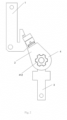
- Fig. 1 shows a switching system in an open state according to one embodiment of the present disclosure.
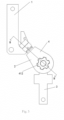
- Figs. 2 and 3 show a switching system in a closed state according to the above embodiment of the present disclosure.
- a stationary contact 1 and an arc-extinguishing grid in Fig. 1 are omitted for simplicity.
- the switching system includes two stationary contacts 1 and one movable contact 2.
- One of the stationary contacts 1 can be connected to a first power supply (not shown), the other of the stationary contacts 1 can be connected to a second power supply (not shown), and the movable contact 2 can be connected to a load (not shown).
- the arc-extinguishing grid is arranged between the two stationary contacts 1.
- the movable contact 2 is in a dual-open position (the movable contact 2 is in open position for the two stationary contacts 1), so that the movable contact 2 is not in contact with any of the stationary contacts 1.
- the movable contact 2 is in a closed position, and the movable contact 2 is in contact with one of the stationary contacts 1 (for the other stationary contact 1, the movable contact 2 is in the opening position), and the first power supply supplies power to the load.
- the movable contact 2 can be switched between the two stationary contacts 1.
- the second power supply supplies power to the load.
- Figs. 4 and 5 show the stationary contact 1 according to one embodiment of the present disclosure.
- One end of the stationary contact 1 is provided with a stationary contact arc striking portion 11, a stationary contact arc contact area 12 and a stationary contact notch 13.
- the other end of the stationary contact 1 can be connected with the first power supply through a power supply input terminal (not shown).
- the movable contact 2 has a clamping structure, which includes a first bracket 21 and a second bracket 22.
- the first bracket 21 and the second bracket 22 are arranged face to face with respect to each other and separated from each other at one of their ends.
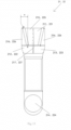
- a movable contact arc contact area 211, 221, a first main contact area 212, 222 and a second main contact area 213, 223 are respectively arranged at one end of the first bracket 21 and of the second bracket 22, and a load-side bulge 214, 224 is arranged at the other end of the first bracket 21 and of the second bracket 22.
- the first main contact area 212, 222 and the second main contact area 213, 223 are arranged side by side.
- the movable contact arc contact area 211, 221 is arranged adjacent to the first main contact area 212, 222 and the second main contact area 213, 223, and closer to an outer edge of the one end of the first bracket 21 and of the second bracket 22 than the first main contact area 212, 222 and the second main contact area 213, 223.
- Gaps exist between the movable contact arc contact area 211, the first main contact area 212 and the second main contact area 213 of the first bracket 21 and the movable contact arc contact area 221, the first main contact area 222 and the second main contact area 223 of the second bracket 22, respectively.
- An oil reservoir 217, 227 is provided between the first main contact area 212, 222 and the second main contact area 213, 223.
- Oil reservoirs 217, 227 are provided between the movable contact arc contact area 211, 221 and the first main contact area 212, 222 and between the movable contact arc contact area 211, 221 and the second main contact area 213, 223.
- the first main contact areas 212, 222, the second main contact areas 213, 223 and the load-side bulge 214, 224 all have arc-shaped outer surfaces, such as spherical outer surfaces.
- the movable contact arc contact area 211, 221 has a flat contact surface 215, 225 and a chamfer 216, 226 located at either side of the contact surface 215, 225.
- the height of the contact surface 215, 225 of the movable contact arc contact area 211, 221 is lower than the highest point of the arc-shaped outer surfaces of the first main contact area 212, 222, the second main contact area 213, 223 and the load-side bulge 214, 224, for example, by a mount of 0.1 mm to 0.5 mm, preferably by 0.3 mm.
- the highest point of the arc-shaped outer surface of the first main contact area 212, 222, the highest point of the arc-shaped outer surface of the second main contact area 213, 223 and the highest point of the arc-shaped outer surface of the load-side bulge 214, 224 have the same height.
- the thickness of the first main contact area 212 and of the second main contact area 213 is greater than that of the arc contact area 211, that is, the first main contact area 212 and the second main contact area 213 are higher than the movable contact arc contact area 211, and that is, the first main contact area 212 and the second main contact area 213 have a height difference h with respect to the movable contact arc contact area 211.
- the first main contact area 212 and the second main contact area 213 have the same thickness.
- the thickness of the first main contact area 222 and the second main contact area 223 is greater than that of the arc contact area 221, that is, the first main contact area 222 and the second main contact area 223 are higher than the movable contact arc contact area 221, and that is, the first main contact area 222 and the second main contact area 223 have a height difference h relative to the movable contact arc contact area 221.
- the thickness of the first main contact area 222 is equal to that of the second main contact area 223.
- the height difference h is, for example, between 0.1 mm and 0.5 mm, preferably 0.3 mm.
- the highest points of the arc-shaped outer surfaces of the first main contact area 212 and of the second main contact area 213 have a position difference s compared with a corresponding edge of a corresponding movable contact arc contact area 211, the edge being formed at the joint between the contact surface 215, 225 and the chamfer 216, 226.
- the highest point of the arc-shaped outer surfaces of the first main contact area 222 and of the second main contact area 223 has a position difference s compared with a corresponding edge of a corresponding movable contact arc contact area 221, the edge being formed at the joint between the contact surface 215, 225 and the chamfer 216, 226.
- the position difference s is between 1 mm and 6 mm, preferably 4 mm.
- the movable contact arc contact area 211, 221, the first main contact area 212, 222 and the second main contact area 213, 223 are all provided for conducting current, wherein when the movable contact 2 is in contact with one of the stationary contacts 1, the movable contact arc contact area 211, 221 and the first main contact area 212, 222 can successively contact with one of the stationary contacts 1. Thereafter, the second main contact area 213, 223 may be or may be not electrically connected to one of the stationary contacts 1 as required. When the movable contact 2 is in contact with the other one of the stationary contacts 1 (not shown), the movable contact arc contact area 211, 221 and the second main contact area 213, 223 can be successively conducted with the other one of the stationary contacts 1. Thereafter, the first main contact area 212, 222 may be or may be not electrically connected to the other one of the stationary contacts 1 as required.
- the movable contact arc contact area 211, 221, the first main contact area 212, 222 and the second main contact area 213, 223 are all made of conductive metal materials and are arranged on one end of the first bracket 21 and of the second bracket 22 by welding, electroplating and/or other methods.
- the other end of the first bracket 21 and of the second bracket 22 are pivotally connected to the output terminal 3 via the load-side bulge 214, 224.
- the output terminal 3 is electrically connected with the load.
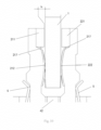
- the movable contact 2 further includes a sleeve 4, a pressure spring 5 and a holder 6 for holding the pressure spring.
- the first bracket 21 and the second bracket 22 are held in the sleeve 4 under the combined action of the sleeve 4, the pressure spring 5 and the holder 6.
- the holder 6 has a ring shape with a rectangular cross section and is held in the sleeve 4, and the first bracket 21, the second bracket 22 and the pressure spring 5 pass through the holder 6.
- the pressure spring 5 acts between the holder 6 and the first bracket 21 and acts between the holder 6 and the second bracket 22, thereby pressing the first bracket 21 and the second bracket 22 toward each other.
- One end of the first bracket 21 and the second bracket 22 extend from the sleeve 4.
- a sleeve driving member 41 is provided outside the sleeve 4.
- a driving mechanism (not shown) drives the sleeve driving member 41 to actuate the first bracket 21 and the second bracket 22 to rotate between the open position and the closed position.
- the sleeve driving member 41 is substantially in the shape of an oblate cylinder.
- the center of the top surface of the sleeve driving member 41 is provided with a spline-shaped depression 412.
- a sleeve partition 42 is provided inside the sleeve 4. Under the action of the pressure spring 5, the first bracket 21 and the second bracket 22 respectively abut against a side of the sleeve partition 42.
- the first main contact area 212, 222, the second main contact area 213, 223 and the movable contact arc contact area 211, 221 in the form of a ramp are respectively arranged on one end of the first bracket 21 and of the second bracket 22.
- a load-side bulge 214, 224 is provided on the other end of the first bracket 21 and of the second bracket 22.
- the movable contact arc contact area 211, 221 shown in Figs. 11 to 15 extend obliquely from the highest point of the first main contact area 212, 222 (as shown by dots in Fig. 13 ) and the highest point of the second main contact area 213, 223 (as shown by dots in Fig. 13 ), respectively.
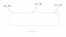
- Figs. 14 and 15 show cross-sectional profiles at both ends of the movable contact arc contact area 211, 221 in the form of a ramp, respectively.
- the first main contact area 212, 222 and the second main contact area 213, 223 are arranged side by side.
- the movable contact arc contact area 211, 221 in the form of a ramp is arranged adjacent to the first main contact area 212, 222 and the second main contact area 213, 223 and closer to the outer edge of one end of the first bracket 21 and the second bracket 22 than the first main contact area 212, 222 and the second main contact area 213, 223.
- Fig. 11 for each of the first bracket 21 and the second bracket 22, there is one movable contact arc contact area in the form of a ramp.
- the first main contact and the second main contact are one respectively, but they may be more than two respectively.
- Gaps exist between the movable contact arc contact area 211, the first main contact area 212 and the second main contact area 213 of the first bracket 21 and between the movable contact arc contact area 221, the first main contact area 222 and the second main contact area 223 of the second bracket 22.
- the movable contact arc contact area and the stationary contact arc contact area are made from different material than that of the main contact areas of the movable contact and the main contact areas of the stationary contacts and embedded (such as welding, powder metallurgy, etc.) in the movable contact and the stationary contacts.
- the movable contact arc contact area and the stationary contact arc contact area are made of high-melting-point alloy (the melting point is higher than that of the material of the main contact areas of the movable contact and the main contact areas of the stationary contacts), which can reduce the wearing speed of the movable contact arc contact area and the stationary contact arc contact area, providing better protection for the main contact areas of the movable contact and the main contact areas of the stationary contacts and thus further improving the electrical performance of the switching system.
- oil reservoirs 217, 227 are provided between the first main contact area 212, 222 and the second main contact area 213, 223.
- the oil reservoir 217, 227 may extend into the movable contact arc contact area 211, 221 in the form of a ramp.
- the first main contact area 212, 222, the second main contact area 213, 223 and the load-side bulge 214, 224 all have arc-shaped outer surfaces, such as spherical outer surfaces.
- the movable contact arc contact area 211, 221 in the form of a ramp has a flat contact surface 215, 225 and a chamfer 216, 226 located at either side of the contact surface 215, 225.
- the movable contact arc contact area 211, 221 in the form of a ramp is lower than the highest points of the arc-shaped outer surfaces of the first main contact area 212, 222, the second main contact area 213, 223 and the load-side bulge 214, 224.
- the highest point of the arc-shaped outer surface of the first main contact area 212, 222, the highest point of the arc-shaped outer surface of the second main contact area 213, 223 and the highest point of the arc-shaped outer surface of the load-side bulge 214, 224 have the same height.
- the plane where the highest points of the first main contact area 212 and the second main contact area 213 are located has an angle difference ⁇ with respect to the movable contact arc contact area 211 in the form of a ramp.
- the plane where the highest points of the first main contact area 222 and the second main contact area 223 are located has an angle difference ⁇ with respect to the movable contact arc contact area 221 in the form of a ramp.
- the angle difference ⁇ is between 1 and 5, preferably 3.
- the highest point of the arc-shaped outer surfaces of the first main contact area 212 and the second main contact area 213 has a position difference s compared with the corresponding edge of the corresponding movable contact arc contact area 211, and the edge is formed at the joint of the contact surface 215, 225 and the chamfer 216, 226.
- the highest points of the arc-shaped outer surfaces of the first main contact area 222 and the second main contact area 223 have a position difference s compared with the corresponding edge of the corresponding movable contact arc contact area 221, and the edge is formed at the joint of the contact surface 215, 225 and the chamfer 216, 226.
- the position difference s is between 1 mm and 6 mm, preferably 4 mm.
- the movable contact arc contact area 211, 221 in the form of a ramp, the first main contact area 212, 222 and the second main contact area 213, 223 are all provided for conducting current, wherein when the movable contact 2 is in contact with one of the stationary contacts 1 (as shown in Figs. 2 and 3 ), the movable contact arc contact area 211, 221 and the first main contact area 212, 222 can contact the one of the stationary contacts 1 one after another. Thereafter, the second main contact area 213, 223 may be or may be not electrically connected to one of the stationary contacts 1 as required.
- the movable contact 2 When the movable contact 2 is in contact with the other one of the stationary contacts 1 (not shown), the movable contact arc contact area 211, 221 and the second main contact area 213, 223 can be successively conducted with the other one of the stationary contacts 1. Thereafter, the first main contact area 212, 222 may be or may be not electrically connected to the other one of the stationary contacts 1 as required.
- the movable contact arc contact area 211, 221 in the form of a ramp, the first main contact area 212, 222 and the second main contact area 213, 223 are all made of conductive metal materials and are arranged on one end of the first bracket 21 and of the second bracket 22 by welding, electroplating and/or other methods.
- a plurality of oil reservoirs 217, 227 can be provided in the movable contact arc contact area 211, 221 in the form of a ramp, wherein in Fig. 18 , the plurality of oil reservoirs 217, 227 extend substantially along the length direction of the first bracket 21 and the second bracket 22; while in Fig. 19 , the plurality of oil reservoirs 217, 227 extend substantially along the width direction of the first bracket 21 and the second bracket 22.
- a switching system such as a dual power changeover switch
- Fig. 1 The overall layout of a switching system according to the present disclosure, such as a dual power changeover switch, is shown in Fig. 1 .
- Fig. 2 and Fig. 3 when the movable contact 2 rotates counterclockwise, it can be connected with the first power supply (not shown).
- the movable contact 2 rotates clockwise (not shown), it can be connected with the second power supply.
- the zone where the movable contact arc contact area 211, 221, the first main contact area 212, 222 and the second main contact area 213, 223 are located is the contact zone.
- a plurality of oil reservoirs 217, 227 are arranged in the contact zone, so that the movable contact 2 has a defined contact point when contacting with the stationary contact 1, and the electrical performance of the switching system is guaranteed.
- the oil reservoirs 217, 227 can store grease for lubrication when there is relative slide between the main contact area of the movable contact and main contact area of the stationary contact, that is, in each closing and opening process of the switching system, for grease to be supplemented to the contact portions of the movable contact and the stationary contacts, thereby reducing the wearing of the contacts and resistance in opening and closing processes, and thereby improving the mechanical and electrical life of the switching system.
- the gradually changing chamfer portion 14 of the stationary contact 1 is easy to be inserted into the contact gaps of the movable contact 2.
- the stationary contact 1 also has the following functional features:
- the gap between the arc contact area 211 of the first bracket 21 and the arc contact area 221 of the second bracket 22 and the gap between the main contact area 212 of the first bracket 21 and the main contact area 222 of the second bracket 22 are smaller than the thickness of the stationary contact 1, as shown in Figs. 9 and 10 ; while when the switching system is closed, the paired first bracket 21 and second bracket 22 can be pushed apart by the stationary contact 1.
- the first and second main contact area 212, 222 and 213, 223 are kept in contact with the main contact area of the stationary contact 15 for carrying rated current and short-circuit current under special working conditions, while the movable contact arc contact area 215 and 225 and the stationary contact arc contact area 12 are kept disengaged to ensure good contact between the main contact areas, thus achieving excellent performance of the switching system with lower temperature rise.
- the conduction of the corresponding arc contact areas of the movable and stationary contacts is always earlier than that of the corresponding main contact areas of the movable and stationary contacts (as shown in Fig. 2 ), until the corresponding main contact areas of the movable and stationary contacts are completely contacted (as shown in Fig. 3 ), since the height difference h between the main contact area of the movable contact and the movable contact arc contact area 215, 225 will raise the movable contact arc contact area 215, 225, separating it from the stationary contact arc contact area 12.
- each corresponding main contact area of the movable contact 2 slides on each corresponding main contact area of the stationary contact 1.
- the movable contact arc contact area 215, 225 is not in contact with the stationary contact arc contact area 12, until the corresponding main contact area of the movable contact slides into the chamfered portion 14, the gap begins to decrease, and the movable contact arc contact area 215, 225 contacts with the stationary contact arc contact area 12, and each corresponding main contact area is separated.
- the movable contact arc contact area 215, 225 is separated from the stationary contact arc contact area 12.
- the arc burns between the stationary contact arc contact area 12 and the movable contact arc contact area 215, 225 and quickly transfers to the arc-extinguishing grid and the movable contact arc contact area 215, 225 to burn until it is extinguished.
- the movable contact arc contact area and the stationary contact arc contact area can protect the main contact areas of the movable contact and the stationary contacts from arc ablation and improve the service life of the switching system.
- the main contact area of the movable contact is kept in contact with the main contact area 15 of the stationary contact, and all the zones where the main contact areas of the movable contact extend outward (including the movable contact arc contact area) are kept separated from the stationary contact.
- the main contact area of the movable contact first slides on the main contact area 15 of the stationary contact.
- the movable contact arc contact area and the stationary contact arc contact area can protect the corresponding main contact areas of the movable contact and the stationary contact from arc ablation, and improve the service life of the switching system.
Landscapes
- Arc-Extinguishing Devices That Are Switches (AREA)
- Contacts (AREA)
- Selective Calling Equipment (AREA)
- Circuits Of Receivers In General (AREA)
Applications Claiming Priority (1)
| Application Number | Priority Date | Filing Date | Title |
|---|---|---|---|
| CN202220814471.6U CN217690826U (zh) | 2022-04-08 | 2022-04-08 | 一种开关系统 |
Publications (3)
| Publication Number | Publication Date |
|---|---|
| EP4258306A1 true EP4258306A1 (de) | 2023-10-11 |
| EP4258306B1 EP4258306B1 (de) | 2026-03-04 |
| EP4258306C0 EP4258306C0 (de) | 2026-03-04 |
Family
ID=83733600
Family Applications (1)
| Application Number | Title | Priority Date | Filing Date |
|---|---|---|---|
| EP23305507.8A Active EP4258306B1 (de) | 2022-04-08 | 2023-04-06 | Schaltsystem |
Country Status (3)
| Country | Link |
|---|---|
| EP (1) | EP4258306B1 (de) |
| CN (1) | CN217690826U (de) |
| AU (1) | AU2023202213B2 (de) |
Cited By (2)
| Publication number | Priority date | Publication date | Assignee | Title |
|---|---|---|---|---|
| EP4415015A1 (de) * | 2023-02-08 | 2024-08-14 | Schneider Electric Industries Sas | Automatischer übertragungsschalter |
| EP4583134A1 (de) * | 2024-01-04 | 2025-07-09 | Schneider Electric Industries Sas | Kontaktanordnung für schaltgerät und schaltgerät |
Citations (5)
| Publication number | Priority date | Publication date | Assignee | Title |
|---|---|---|---|---|
| CH330629A (de) * | 1954-03-10 | 1958-06-15 | Siemens Ag | Elektrischer Schalter mit Vor- und Hauptkontaktstellen, insbesondere Hebelschalter |
| JPS4934960U (de) * | 1972-06-30 | 1974-03-27 | ||
| WO2002003410A1 (en) * | 2000-06-29 | 2002-01-10 | Siemens Energy & Automation, Inc. | Switch contact configuration |
| CN201663090U (zh) * | 2010-03-31 | 2010-12-01 | 浙江紫光电器有限公司 | 充气式负荷开关中的静刀 |
| EP3457422A1 (de) * | 2017-09-15 | 2019-03-20 | ABB Oy | Elektrischer schalter |
-
2022
- 2022-04-08 CN CN202220814471.6U patent/CN217690826U/zh active Active
-
2023
- 2023-04-06 EP EP23305507.8A patent/EP4258306B1/de active Active
- 2023-04-11 AU AU2023202213A patent/AU2023202213B2/en active Active
Patent Citations (5)
| Publication number | Priority date | Publication date | Assignee | Title |
|---|---|---|---|---|
| CH330629A (de) * | 1954-03-10 | 1958-06-15 | Siemens Ag | Elektrischer Schalter mit Vor- und Hauptkontaktstellen, insbesondere Hebelschalter |
| JPS4934960U (de) * | 1972-06-30 | 1974-03-27 | ||
| WO2002003410A1 (en) * | 2000-06-29 | 2002-01-10 | Siemens Energy & Automation, Inc. | Switch contact configuration |
| CN201663090U (zh) * | 2010-03-31 | 2010-12-01 | 浙江紫光电器有限公司 | 充气式负荷开关中的静刀 |
| EP3457422A1 (de) * | 2017-09-15 | 2019-03-20 | ABB Oy | Elektrischer schalter |
Cited By (2)
| Publication number | Priority date | Publication date | Assignee | Title |
|---|---|---|---|---|
| EP4415015A1 (de) * | 2023-02-08 | 2024-08-14 | Schneider Electric Industries Sas | Automatischer übertragungsschalter |
| EP4583134A1 (de) * | 2024-01-04 | 2025-07-09 | Schneider Electric Industries Sas | Kontaktanordnung für schaltgerät und schaltgerät |
Also Published As
| Publication number | Publication date |
|---|---|
| AU2023202213A1 (en) | 2023-10-26 |
| EP4258306B1 (de) | 2026-03-04 |
| AU2023202213B2 (en) | 2024-05-16 |
| CN217690826U (zh) | 2022-10-28 |
| EP4258306C0 (de) | 2026-03-04 |
Similar Documents
| Publication | Publication Date | Title |
|---|---|---|
| AU2023202213B2 (en) | A switching system | |
| CN111194473B (zh) | 电气开关 | |
| US9281138B2 (en) | Parallel type transfer switch contacts assemblies | |
| US4594489A (en) | Electrical switching element | |
| EP2442338B1 (de) | Kontakt für Vakuumunterbrecher | |
| CN111095462A (zh) | 电气开关 | |
| CN212136276U (zh) | 电气开关 | |
| EP4258305B1 (de) | Schaltsystem mit bypass-kontakt | |
| CN100437854C (zh) | 用于分接开关的负荷变换器 | |
| EP1297544B1 (de) | Schalter mit vor- und hauptkontakten | |
| US2606983A (en) | Circuit interrupter contact | |
| AU2001271128A1 (en) | Switch with auxiliary and main contacts | |
| JP2004273235A (ja) | 回路遮断器 | |
| CN217008949U (zh) | 一种具有多点接触的动触头的开关系统 | |
| RU2178927C1 (ru) | Контактная система вакуумной дугогасительной камеры (варианты) | |
| CN117043905A (zh) | 开关装置 | |
| CN217822414U (zh) | 动触桥及触头装置 | |
| CN114041197A (zh) | 开关装置的电接触系统 | |
| JPS6340827Y2 (de) | ||
| US3147358A (en) | Magnetic blowout contact switch | |
| CN222380533U (zh) | 触头组件及断路器 | |
| CN204966380U (zh) | 一种真空灭弧室 | |
| FR2985080A1 (fr) | Ensemble de connexion electrique | |
| JPS61173418A (ja) | 接点開閉装置 | |
| KR102078921B1 (ko) | 고압 및 대전류에 견딜 수 있는 릴레이 |
Legal Events
| Date | Code | Title | Description |
|---|---|---|---|
| PUAI | Public reference made under article 153(3) epc to a published international application that has entered the european phase |
Free format text: ORIGINAL CODE: 0009012 |
|
| STAA | Information on the status of an ep patent application or granted ep patent |
Free format text: STATUS: THE APPLICATION HAS BEEN PUBLISHED |
|
| AK | Designated contracting states |
Kind code of ref document: A1 Designated state(s): AL AT BE BG CH CY CZ DE DK EE ES FI FR GB GR HR HU IE IS IT LI LT LU LV MC ME MK MT NL NO PL PT RO RS SE SI SK SM TR |
|
| STAA | Information on the status of an ep patent application or granted ep patent |
Free format text: STATUS: REQUEST FOR EXAMINATION WAS MADE |
|
| 17P | Request for examination filed |
Effective date: 20240411 |
|
| RBV | Designated contracting states (corrected) |
Designated state(s): AL AT BE BG CH CY CZ DE DK EE ES FI FR GB GR HR HU IE IS IT LI LT LU LV MC ME MK MT NL NO PL PT RO RS SE SI SK SM TR |
|
| GRAP | Despatch of communication of intention to grant a patent |
Free format text: ORIGINAL CODE: EPIDOSNIGR1 |
|
| STAA | Information on the status of an ep patent application or granted ep patent |
Free format text: STATUS: GRANT OF PATENT IS INTENDED |
|
| RIC1 | Information provided on ipc code assigned before grant |
Ipc: H01H 1/42 20060101AFI20250919BHEP Ipc: H01H 9/38 20060101ALI20250919BHEP Ipc: H01H 9/36 20060101ALN20250919BHEP |
|
| INTG | Intention to grant announced |
Effective date: 20251008 |
|
| GRAS | Grant fee paid |
Free format text: ORIGINAL CODE: EPIDOSNIGR3 |
|
| GRAA | (expected) grant |
Free format text: ORIGINAL CODE: 0009210 |
|
| STAA | Information on the status of an ep patent application or granted ep patent |
Free format text: STATUS: THE PATENT HAS BEEN GRANTED |
|
| AK | Designated contracting states |
Kind code of ref document: B1 Designated state(s): AL AT BE BG CH CY CZ DE DK EE ES FI FR GB GR HR HU IE IS IT LI LT LU LV MC ME MK MT NL NO PL PT RO RS SE SI SK SM TR |
|
| REG | Reference to a national code |
Ref country code: CH Ref legal event code: F10 Free format text: ST27 STATUS EVENT CODE: U-0-0-F10-F00 (AS PROVIDED BY THE NATIONAL OFFICE) Effective date: 20260304 Ref country code: GB Ref legal event code: FG4D |
|
| REG | Reference to a national code |
Ref country code: DE Ref legal event code: R096 Ref document number: 602023012966 Country of ref document: DE |
|
| REG | Reference to a national code |
Ref country code: IE Ref legal event code: FG4D |
|
| U01 | Request for unitary effect filed |
Effective date: 20260304 |
|
| U07 | Unitary effect registered |
Designated state(s): AT BE BG DE DK EE FI FR IT LT LU LV MT NL PT RO SE SI Effective date: 20260311 |