EP4258431A1 - Élément de collecte de courant, cellule et dispositif électronique - Google Patents
Élément de collecte de courant, cellule et dispositif électronique Download PDFInfo
- Publication number
- EP4258431A1 EP4258431A1 EP22207806.5A EP22207806A EP4258431A1 EP 4258431 A1 EP4258431 A1 EP 4258431A1 EP 22207806 A EP22207806 A EP 22207806A EP 4258431 A1 EP4258431 A1 EP 4258431A1
- Authority
- EP
- European Patent Office
- Prior art keywords
- main body
- body structure
- electrode assembly
- current collecting
- collecting member
- Prior art date
- Legal status (The legal status is an assumption and is not a legal conclusion. Google has not performed a legal analysis and makes no representation as to the accuracy of the status listed.)
- Pending
Links
Images


Classifications
-
- H—ELECTRICITY
- H01—ELECTRIC ELEMENTS
- H01M—PROCESSES OR MEANS, e.g. BATTERIES, FOR THE DIRECT CONVERSION OF CHEMICAL ENERGY INTO ELECTRICAL ENERGY
- H01M10/00—Secondary cells; Manufacture thereof
- H01M10/04—Construction or manufacture in general
-
- H—ELECTRICITY
- H01—ELECTRIC ELEMENTS
- H01M—PROCESSES OR MEANS, e.g. BATTERIES, FOR THE DIRECT CONVERSION OF CHEMICAL ENERGY INTO ELECTRICAL ENERGY
- H01M50/00—Constructional details or processes of manufacture of the non-active parts of electrochemical cells other than fuel cells, e.g. hybrid cells
- H01M50/10—Primary casings; Jackets or wrappings
- H01M50/102—Primary casings; Jackets or wrappings characterised by their shape or physical structure
- H01M50/103—Primary casings; Jackets or wrappings characterised by their shape or physical structure prismatic or rectangular
-
- H—ELECTRICITY
- H01—ELECTRIC ELEMENTS
- H01M—PROCESSES OR MEANS, e.g. BATTERIES, FOR THE DIRECT CONVERSION OF CHEMICAL ENERGY INTO ELECTRICAL ENERGY
- H01M50/00—Constructional details or processes of manufacture of the non-active parts of electrochemical cells other than fuel cells, e.g. hybrid cells
- H01M50/10—Primary casings; Jackets or wrappings
- H01M50/147—Lids or covers
- H01M50/148—Lids or covers characterised by their shape
- H01M50/15—Lids or covers characterised by their shape for prismatic or rectangular cells
-
- H—ELECTRICITY
- H01—ELECTRIC ELEMENTS
- H01M—PROCESSES OR MEANS, e.g. BATTERIES, FOR THE DIRECT CONVERSION OF CHEMICAL ENERGY INTO ELECTRICAL ENERGY
- H01M50/00—Constructional details or processes of manufacture of the non-active parts of electrochemical cells other than fuel cells, e.g. hybrid cells
- H01M50/40—Separators; Membranes; Diaphragms; Spacing elements inside cells
- H01M50/471—Spacing elements inside cells other than separators, membranes or diaphragms; Manufacturing processes thereof
- H01M50/474—Spacing elements inside cells other than separators, membranes or diaphragms; Manufacturing processes thereof characterised by their position inside the cells
-
- H—ELECTRICITY
- H01—ELECTRIC ELEMENTS
- H01M—PROCESSES OR MEANS, e.g. BATTERIES, FOR THE DIRECT CONVERSION OF CHEMICAL ENERGY INTO ELECTRICAL ENERGY
- H01M50/00—Constructional details or processes of manufacture of the non-active parts of electrochemical cells other than fuel cells, e.g. hybrid cells
- H01M50/40—Separators; Membranes; Diaphragms; Spacing elements inside cells
- H01M50/471—Spacing elements inside cells other than separators, membranes or diaphragms; Manufacturing processes thereof
- H01M50/48—Spacing elements inside cells other than separators, membranes or diaphragms; Manufacturing processes thereof characterised by the material
- H01M50/486—Organic material
-
- H—ELECTRICITY
- H01—ELECTRIC ELEMENTS
- H01M—PROCESSES OR MEANS, e.g. BATTERIES, FOR THE DIRECT CONVERSION OF CHEMICAL ENERGY INTO ELECTRICAL ENERGY
- H01M50/00—Constructional details or processes of manufacture of the non-active parts of electrochemical cells other than fuel cells, e.g. hybrid cells
- H01M50/50—Current conducting connections for cells or batteries
- H01M50/531—Electrode connections inside a battery casing
- H01M50/533—Electrode connections inside a battery casing characterised by the shape of the leads or tabs
-
- H—ELECTRICITY
- H01—ELECTRIC ELEMENTS
- H01M—PROCESSES OR MEANS, e.g. BATTERIES, FOR THE DIRECT CONVERSION OF CHEMICAL ENERGY INTO ELECTRICAL ENERGY
- H01M50/00—Constructional details or processes of manufacture of the non-active parts of electrochemical cells other than fuel cells, e.g. hybrid cells
- H01M50/50—Current conducting connections for cells or batteries
- H01M50/531—Electrode connections inside a battery casing
- H01M50/534—Electrode connections inside a battery casing characterised by the material of the leads or tabs
-
- H—ELECTRICITY
- H01—ELECTRIC ELEMENTS
- H01M—PROCESSES OR MEANS, e.g. BATTERIES, FOR THE DIRECT CONVERSION OF CHEMICAL ENERGY INTO ELECTRICAL ENERGY
- H01M50/00—Constructional details or processes of manufacture of the non-active parts of electrochemical cells other than fuel cells, e.g. hybrid cells
- H01M50/50—Current conducting connections for cells or batteries
- H01M50/531—Electrode connections inside a battery casing
- H01M50/536—Electrode connections inside a battery casing characterised by the method of fixing the leads to the electrodes, e.g. by welding
-
- H—ELECTRICITY
- H01—ELECTRIC ELEMENTS
- H01M—PROCESSES OR MEANS, e.g. BATTERIES, FOR THE DIRECT CONVERSION OF CHEMICAL ENERGY INTO ELECTRICAL ENERGY
- H01M50/00—Constructional details or processes of manufacture of the non-active parts of electrochemical cells other than fuel cells, e.g. hybrid cells
- H01M50/50—Current conducting connections for cells or batteries
- H01M50/531—Electrode connections inside a battery casing
- H01M50/538—Connection of several leads or tabs of wound or folded electrode stacks
-
- H—ELECTRICITY
- H01—ELECTRIC ELEMENTS
- H01M—PROCESSES OR MEANS, e.g. BATTERIES, FOR THE DIRECT CONVERSION OF CHEMICAL ENERGY INTO ELECTRICAL ENERGY
- H01M50/00—Constructional details or processes of manufacture of the non-active parts of electrochemical cells other than fuel cells, e.g. hybrid cells
- H01M50/50—Current conducting connections for cells or batteries
- H01M50/543—Terminals
- H01M50/547—Terminals characterised by the disposition of the terminals on the cells
- H01M50/55—Terminals characterised by the disposition of the terminals on the cells on the same side of the cell
-
- Y—GENERAL TAGGING OF NEW TECHNOLOGICAL DEVELOPMENTS; GENERAL TAGGING OF CROSS-SECTIONAL TECHNOLOGIES SPANNING OVER SEVERAL SECTIONS OF THE IPC; TECHNICAL SUBJECTS COVERED BY FORMER USPC CROSS-REFERENCE ART COLLECTIONS [XRACs] AND DIGESTS
- Y02—TECHNOLOGIES OR APPLICATIONS FOR MITIGATION OR ADAPTATION AGAINST CLIMATE CHANGE
- Y02E—REDUCTION OF GREENHOUSE GAS [GHG] EMISSIONS, RELATED TO ENERGY GENERATION, TRANSMISSION OR DISTRIBUTION
- Y02E60/00—Enabling technologies; Technologies with a potential or indirect contribution to GHG emissions mitigation
- Y02E60/10—Energy storage using batteries
Definitions
- the disclosure relates to the technical field of secondary batteries, in particular to a current collecting member, a cell and an electronic device.
- electrode assembly needs to output the current uniformly through the current collecting member.
- the surface of the current collecting member especially the edge and corner of the current collecting member, will cause the tab to be worn, and it is very likely to cause damage to the tab and affect the service life of battery.
- the purpose of the present disclosure is to provide a current collecting member, a cell and an electronic device to solve the problem of wear occurred between the tab portion and the current collecting member.
- a current collecting member which includes a main body structure and a lead-out structure.
- the main body structure is further provided with a protection member, at least one end of the protection member is bent along the width direction of the main body structure and wraps the corner portion of the main body structure in the thickness direction.
- an electronic device is provided, which includes the above-mentioned cell.
- the advantageous effects of the present disclosure are as follows:
- the overall structure of the current collecting member of the disclosure is simple, so as to reduce the wear between the tab portion and the main body structure, thereby effectively protecting the tab portion.
- connection may be a fixed connection, a detachable connection, a mechanical connection, an electrical connection, a direct connection, an indirect connection through an intermediate medium, or may be an internal connection between two elements or an interaction relationship between two elements.
- connection may be a fixed connection, a detachable connection, a mechanical connection, an electrical connection, a direct connection, an indirect connection through an intermediate medium, or may be an internal connection between two elements or an interaction relationship between two elements.
- the first feature "on” or “under” the second feature may include direct contact between the first feature and the second feature, or may include indirect contact through an additional feature between the first feature and the second feature instead of direct contact between them.
- the first feature being “above”, “over” and “on top of' the second feature includes the first feature being directly above and obliquely above the second feature, or simply means that the first feature is at a higher level than the second feature.
- the first feature being “below”, “under” and “beneath” the second feature includes the first feature being directly below and obliquely below the second feature, or simply means that the first feature is at a lower level than the second feature.
- electronic devices may include, but are not limited to, notebook computers, pen input computers, mobile computers, e-book players, portable telephones, portable fax machines, portable copiers, portable printers, headsets, VCRs, LCD TVs, portable cleaners, portable CD players, mini discs, transceivers, electronic notepads, calculators, memory cards, portable recorders, radios, backup power supplies, motors, automobiles, motorcycles, assisted bicycles, bicycles, lighting equipment, toys, game consoles, clocks, power tools, flashlights, cameras, large-scale household storage batteries and lithium-ion capacitors, etc.
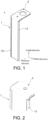
- the present disclosure provides a current collecting member, which includes a main body structure 1 and a lead-out structure 2 for drawing out current.
- the main body structure 1 is arranged at one end of the electrode assembly 100, and the main body structure 1 is parallel or substantially parallel to a lateral surface 105 of the electrode assembly, and extends along the width direction of the electrode assembly 100.
- the main body structure 1 and the lead-out structure 2 are integrally formed, and the main body structure 1 is bent relative to the lead-out structure 2 in a direction away from the cover plate assembly 102.
- the tab portion 101 is bent toward one side of the main body structure 1 away from the electrode assembly 100 along one end of the main body structure 1 in the width direction and is connected with the main body structure 1.
- the main body structure 1 is further provided with a protection member 13.
- the material of the protection member 13 includes at least one of polypropylene, ethylene phthalate or polyimide.
- the protection member 13 covers one side of the main body structure 1 close to the electrode assembly 100, and is bent along one end of the main body structure 1 in the width direction and wraps the corner portion of the main body structure 1 in the thickness direction.
- the structure of the current collecting member is shown in FIG. 1 , and the directions indicated by the arrows in FIG. 1 are the length, width, and thickness directions of the main body structure 1.
- FIG. 7 For a schematic diagram of the connection between the current collecting member and the electrode assembly 100, please refer to FIG. 7 .
- the electrode assembly 100 is an oblong rectangular cell, and the directions indicated by the arrows in FIG. 7 are the length, width, and thickness directions of the electrode assembly 100.
- the main body structure 1 of the current collecting member is disposed at one end of the electrode assembly 100 in the length direction, parallel or substantially parallel to the lateral surface 105 of the electrode assembly.
- the lead-out structure 2 is connected with the cover plate assembly 102, and the main body structure 1 is bent relative to the lead-out structure 2 in a direction away from the cover plate assembly 102 and extends along the width direction of the electrode assembly 100.
- the tab portion 101 led out from the electrode assembly 100 is bent around one side of the main body structure 1 in the width direction and connected to one side of the main body structure 1 away from the electrode assembly 100.
- the directions indicated by the arrows in FIG. 10 are the length and thickness directions of the electrode assembly 100 respectively.
- the thickness direction of the main body structure 1 is in the same direction as the length direction of the electrode assembly 100.
- a protection member 13 is provided on one side of the main body structure 1 close to the electrode assembly 100 and the corner portion of the main body structure 1 in the thickness direction. In this manner, it is possible to reduce the wear between the tab portion 101 and the main body structure 1, and the tabs are effectively protected.
- the protection member 13 may be a back adhesive layer or a polyester-based substance.
- At least part of the outer edge at one side of the main body structure 1 away from the electrode assembly 100 is provided with an accommodating groove 12, and the accommodating groove 12 extends along the length direction of the main body structure 1.
- the ratio of the depth of the accommodating groove 12 to the thickness of the main body structure 1 is in the range of 1/10 to 2/3.
- an accommodating groove 12 may be provided at least partially at the outer edge in the length direction at one side of the main body structure 1 away from the electrode assembly 100.
- the accommodating groove 12 may partially reduce the thickness of the edge of the main body structure 1 and reduce the amount of materials used.
- the tab portion 101 is bent around the main body structure 1, the total thickness of the bent portion of the tab portion 101 and the main body structure 1 may be reduced.
- FIG. 10 when the tab portion 101 is bent around the main body structure 1, since the outer edge in the length direction at one side of the main body structure 1 away from the electrode assembly 100 is provided with an accommodating groove 12 (not shown in FIG.
- the bending portion of the tab portion 101 along the thickness direction of the main body structure 1 and the total thickness of the main body structure 1 are reduced, so as to improve the energy density of the electrode assembly 100.
- the ratio of the depth of the accommodating groove 12 to the thickness of the main body structure 1 may be, but is not limited to, within a range formed by any two of 0.1, 0.2, 0.5 or 2/3. If the depth of the accommodating groove 12 is too deep, both ends of the main body structure 1 in the width direction will become thinner, which will affect the structural strength of the main body structure 1. If the depth of the accommodating groove 12 is too small, the bending part of the tab portion 101 along the thickness direction of the main body structure 1 and the overall thickness of the main body structure 1 will be too large.
- the protection member 13 at least partially covers the accommodating groove 12. It can be understood that the protection member 13 serves the function of protecting the tab portion 101 and reducing the wear between the tab portion 101 and the main body structure 1.
- the protection member 13 has a certain thickness, and the groove depth of the accommodating groove 12 is greater than or equal to the thickness of the protection member 13. In this manner, after the protection member 13 covers the accommodating groove 12, the protection member 13 will not protrude from the surface of the main body structure 1 and affect the overall size of the current collecting member in the thickness direction.
- a protection member 1011 is sleeved on the tab portion 101, and one side of the protection member 1011 is attached to one side of the main body structure 1 away from the electrode assembly 100.
- the protection member 1011 is sleeved on the tab portion 101, the protection member 1011 protects the tab portion 101, and the protection member 1011 is welded and connected to one side of the main body structure 1 away from the electrode assembly 100.
- the tab portion 101 is not directly welded with the main body structure 1 to prevent the tab portion 101 from being damaged.
- the electrode assembly 100 is provided with two sets.
- the tab portion 101 of one set of electrode assemblies 100 is led out in a direction away from the other set of electrode assemblies 100.
- the tab portions 101 of the two sets of electrode assemblies 100 are bent respectively around both ends of the main body structure 1 in the width direction.
- the main body structure 1 in this embodiment is correspondingly connected to the tab portions 101 of the two sets of electrode assemblies 100.
- the tab portions 101 of the two sets of electrode assemblies 100 are bent respectively around both ends of the main body structure 1 in the width direction.
- FIG. 10 of this embodiment shows the connection between the two sets of electrode assemblies 100 and the main body structure 1.
- the protection member 13 covers one side of the main body structure 1 close to the electrode assembly 100, and is bent along both ends of the main body structure 1 in the width direction and wraps two corner portions in the thickness direction.
- the two tab portions 101 at the same end of the two sets of electrode assemblies 100 are connected and output through one current collecting member, which reduces the number of current collecting members, improves the energy density of the electrode assembly 100 and reduces the production cost.
- the electrode assemblies 100 may be arranged in a set, and the protection member 13 covers one side of the main body structure 1 close to the electrode assembly 100 and the corner portion of the main body structure 1 on one side where the tab portion 101 is bent, which is not limited to the illustration in FIG. 10 .
- the main body structure 1 is further provided with a reinforcing rib 11, and the reinforcing rib 11 extends along the length direction of the main body structure 1.
- the main body structure 1 is provided with a reinforcing rib 11 in the length direction.
- the reinforcing rib 11 is arranged on one side of the main body structure 1 away from the electrode assembly 100.
- the reinforcing rib 11 facilitates to improve the structural strength of the main body structure 1, and the shape of the reinforcing rib 11 may also be a straight line, a wavy line, or other shapes and structures, etc., and is not limited to the shape shown in FIG. 3 of this embodiment.
- This embodiment further provides a cell, which includes an electrode assembly 100, a cover plate assembly 102 and the current collecting member.
- the electrode assembly 100 includes a tab portion 101 led out from a lateral surface 105 of the electrode assembly 100, and the cover plate assembly 102 is located on the top surface of the electrode assembly 102.
- the cover plate assembly 102 includes a pole 103.
- the lead-out structure 2 is located on the top surface of the electrode assembly 100 and is connected to the pole 103, and the tab portion 101 is connected to the main body structure 1.
- the main body structure 1 of the current collecting member is parallel to the lateral surface 105 of the electrode assembly 100.
- the lead-out structure 2 is located on the top surface of the electrode assembly 100 and is connected to the pole 103.
- One side of the main body structure 1 close to the electrode assembly 100 and the corner portions of the main body structure 1 in the thickness direction are both provided with protection members 13 (as shown in FIG. 10 ).
- the tab portion 101 is bent along one end of the main body structure 1 in the width direction and connected to one side of the main body structure 1 away from the electrode assembly 100. The wear between the current collecting member of the cell and the tab portion 101 is small, and the performance and service life of the cell are significantly improved.
- the cell further includes a housing 104, the housing 104 is sheathed outside the two sets of electrode assemblies 100 and is fixedly connected to the cover plate assembly 102.
- the above-mentioned cell further includes a housing 104, and the housing 104 is connected to the cover plate assembly 102 after sheathing the electrode assembly 100 to package and protect the electrode assembly 100 and other components.
- This embodiment further provides an electronic device including a plurality of the above-mentioned cells.
- the electronic device has good performance, less wear between the tab portion 101 and the current collecting member, and has a long service life.
- At least part of the outer edge of the main body structure is provided with an accommodating groove.
- the ratio of the depth of the accommodating groove to the thickness of the main body structure is in the range of 1/10 to 2/3, and the length direction of the accommodating groove is parallel to the length direction of the main body structure.
- the protection member at least partially covers one end of the accommodating groove close to the main body structure in the width direction.
- the thickness of the protection member is less than or equal to the depth of the accommodating groove.
- the main body structure and the lead-out structure are integrally formed.
- a reinforcing rib is further provided on the main body structure, and the reinforcing rib extends along the length direction of the main body structure.
- the material of the protection member includes at least one of polypropylene, polyethylene terephthalate or polyimide.
- a cell which includes an electrode assembly, a cover plate assembly and the above-mentioned current collecting member.
- the cover plate assembly is located on the top surface of the electrode assembly, the cover plate assembly includes a pole.
- the lead-out structure is located on the top surface of the electrode assembly and connected with the pole.
- the main body structure is disposed at one end of the electrode assembly in the length direction.
- One end of the electrode assembly is provided with a tab portion, and the tab portion is bent toward one side of the main body structure away from the electrode assembly along one end of the main body structure in the width direction and is connected with the main body structure.
- the electrode assembly is provided in two sets.
- the tab portion of one set of the electrode assemblies is led out in a direction away from the other set of the electrode assemblies.
- the tab portions of the two sets of the electrode assemblies are bent respectively around both ends of the main body structure in the width direction.
- the main body structure is parallel or substantially parallel to the lateral surface of the electrode assembly, and extends along the width direction of the electrode assembly.
- the main body structure is disposed vertically or substantially vertically relative to the lead-out structure in a direction away from the cover plate assembly.
- the cell further includes a housing, which is sheathed outside the electrode assembly and is fixedly connected to the cover plate assembly.
- At least one side of the tab portion is provided with a protection member, and one side of the protection member is attached to one side of the main body structure away from the electrode assembly.
Landscapes
- Chemical & Material Sciences (AREA)
- Chemical Kinetics & Catalysis (AREA)
- Electrochemistry (AREA)
- General Chemical & Material Sciences (AREA)
- Engineering & Computer Science (AREA)
- Manufacturing & Machinery (AREA)
- Connection Of Batteries Or Terminals (AREA)
- Sealing Battery Cases Or Jackets (AREA)
Applications Claiming Priority (1)
| Application Number | Priority Date | Filing Date | Title |
|---|---|---|---|
| CN202220801234.6U CN217134598U (zh) | 2022-04-07 | 2022-04-07 | 一种转接片、电池单元及电子设备 |
Publications (1)
| Publication Number | Publication Date |
|---|---|
| EP4258431A1 true EP4258431A1 (fr) | 2023-10-11 |
Family
ID=82647460
Family Applications (1)
| Application Number | Title | Priority Date | Filing Date |
|---|---|---|---|
| EP22207806.5A Pending EP4258431A1 (fr) | 2022-04-07 | 2022-11-16 | Élément de collecte de courant, cellule et dispositif électronique |
Country Status (4)
| Country | Link |
|---|---|
| US (1) | US20230327296A1 (fr) |
| EP (1) | EP4258431A1 (fr) |
| JP (1) | JP7623993B2 (fr) |
| CN (1) | CN217134598U (fr) |
Families Citing this family (5)
| Publication number | Priority date | Publication date | Assignee | Title |
|---|---|---|---|---|
| KR20240057717A (ko) * | 2022-10-25 | 2024-05-03 | 삼성에스디아이 주식회사 | 이차 전지 |
| CN115939688B (zh) * | 2022-12-28 | 2026-04-14 | 株式会社Aesc日本 | 电芯结构、电池模块及电池包 |
| US20240222806A1 (en) * | 2022-12-30 | 2024-07-04 | Aesc Japan Ltd. | Pin structure and battery cell assembly |
| CN219419418U (zh) * | 2023-04-07 | 2023-07-25 | 远景动力技术(江苏)有限公司 | 盖板组件及包含其的单体电池 |
| CN121195406A (zh) * | 2024-01-04 | 2025-12-23 | 宁德时代新能源科技股份有限公司 | 电池单体、电池及用电装置 |
Citations (3)
| Publication number | Priority date | Publication date | Assignee | Title |
|---|---|---|---|---|
| JP2011071109A (ja) * | 2009-08-27 | 2011-04-07 | Toshiba Corp | 電池 |
| EP3451415A1 (fr) * | 2017-08-31 | 2019-03-06 | Samsung SDI Co., Ltd. | Batterie secondaire |
| US20200373547A1 (en) * | 2019-05-24 | 2020-11-26 | Contemporary Amperex Technology Co., Limited | Battery unit and manufacturing method thereof, and battery module |
Family Cites Families (6)
| Publication number | Priority date | Publication date | Assignee | Title |
|---|---|---|---|---|
| US8574753B2 (en) * | 2009-08-27 | 2013-11-05 | Kabushiki Kaisha Toshiba | Battery comprising a conductive nipping member |
| US20110200865A1 (en) | 2010-02-18 | 2011-08-18 | Sang-Won Byun | Secondary battery and battery module including the same |
| JP2016139491A (ja) | 2015-01-26 | 2016-08-04 | 株式会社Gsユアサ | 蓄電素子 |
| JP2019067595A (ja) | 2017-09-29 | 2019-04-25 | 株式会社Gsユアサ | 蓄電素子 |
| CN111864172B (zh) * | 2019-04-25 | 2025-01-17 | 宁德时代新能源科技股份有限公司 | 电池单元和电池模组 |
| CN111048728B (zh) * | 2020-03-18 | 2020-06-23 | 江苏时代新能源科技有限公司 | 二次电池、电池模块以及使用二次电池作为电源的装置 |
-
2022
- 2022-04-07 CN CN202220801234.6U patent/CN217134598U/zh active Active
- 2022-10-31 US US17/978,084 patent/US20230327296A1/en active Pending
- 2022-11-16 EP EP22207806.5A patent/EP4258431A1/fr active Pending
- 2022-12-21 JP JP2022204076A patent/JP7623993B2/ja active Active
Patent Citations (3)
| Publication number | Priority date | Publication date | Assignee | Title |
|---|---|---|---|---|
| JP2011071109A (ja) * | 2009-08-27 | 2011-04-07 | Toshiba Corp | 電池 |
| EP3451415A1 (fr) * | 2017-08-31 | 2019-03-06 | Samsung SDI Co., Ltd. | Batterie secondaire |
| US20200373547A1 (en) * | 2019-05-24 | 2020-11-26 | Contemporary Amperex Technology Co., Limited | Battery unit and manufacturing method thereof, and battery module |
Also Published As
| Publication number | Publication date |
|---|---|
| US20230327296A1 (en) | 2023-10-12 |
| JP7623993B2 (ja) | 2025-01-29 |
| JP2023155143A (ja) | 2023-10-20 |
| CN217134598U (zh) | 2022-08-05 |
Similar Documents
| Publication | Publication Date | Title |
|---|---|---|
| EP4258431A1 (fr) | Élément de collecte de courant, cellule et dispositif électronique | |
| EP4207477A1 (fr) | Dispositif électrochimique et dispositif électronique | |
| US7166389B2 (en) | Battery pack and method for producing same | |
| CN104377339B (zh) | 可再充电电池组 | |
| US9431636B2 (en) | Rechargeable battery | |
| CN115347291B (zh) | 电化学装置和电子装置 | |
| CN218632377U (zh) | 电池和电子设备 | |
| CN113782917A (zh) | 连接件、电池组及用电设备 | |
| CN113597709B (zh) | 电池和具有所述电池的电子装置 | |
| US20250046966A1 (en) | Battery and electronic device | |
| CN112510240A (zh) | 二次电池和终端设备 | |
| KR20230018072A (ko) | 배터리 팩 | |
| KR20040054113A (ko) | 파우치형 케이스와, 이를 적용한 리튬 이차 전지 | |
| EP4583215A1 (fr) | Batterie et appareil électronique | |
| US11552339B2 (en) | Battery pack with overmolded module | |
| CN216055068U (zh) | 连接件、电池组及用电设备 | |
| EP4095990A1 (fr) | Élément de batterie, bloc-batterie et dispositif électronique | |
| CN222355197U (zh) | 电池组件及用电设备 | |
| CN212625746U (zh) | 电池、电池组及电子装置 | |
| CN219626764U (zh) | 电池单体、电池及用电设备 | |
| EP4503323A1 (fr) | Batterie et dispositif électronique | |
| EP4507073A1 (fr) | Appareil électrochimique, module de batterie et dispositif électronique | |
| WO2024088391A1 (fr) | Batterie, module de batterie, bloc-batterie et dispositif électrique | |
| CN223612465U (zh) | 二次电池及用电设备 | |
| CN223927451U (zh) | 电池包 |
Legal Events
| Date | Code | Title | Description |
|---|---|---|---|
| PUAI | Public reference made under article 153(3) epc to a published international application that has entered the european phase |
Free format text: ORIGINAL CODE: 0009012 |
|
| STAA | Information on the status of an ep patent application or granted ep patent |
Free format text: STATUS: REQUEST FOR EXAMINATION WAS MADE |
|
| 17P | Request for examination filed |
Effective date: 20221116 |
|
| AK | Designated contracting states |
Kind code of ref document: A1 Designated state(s): AL AT BE BG CH CY CZ DE DK EE ES FI FR GB GR HR HU IE IS IT LI LT LU LV MC ME MK MT NL NO PL PT RO RS SE SI SK SM TR |
|
| RBV | Designated contracting states (corrected) |
Designated state(s): AL AT BE BG CH CY CZ DE DK EE ES FI FR GB GR HR HU IE IS IT LI LT LU LV MC ME MK MT NL NO PL PT RO RS SE SI SK SM TR |