EP4258452A1 - Connecteur électrique pour connecter les bornes de deux modules de batterie adjacents l'un à l'autre dans un système de stockage d'énergie - Google Patents
Connecteur électrique pour connecter les bornes de deux modules de batterie adjacents l'un à l'autre dans un système de stockage d'énergie Download PDFInfo
- Publication number
- EP4258452A1 EP4258452A1 EP23166680.1A EP23166680A EP4258452A1 EP 4258452 A1 EP4258452 A1 EP 4258452A1 EP 23166680 A EP23166680 A EP 23166680A EP 4258452 A1 EP4258452 A1 EP 4258452A1
- Authority
- EP
- European Patent Office
- Prior art keywords
- electrical connector
- shell
- retaining sheet
- hole
- conductor bar
- Prior art date
- Legal status (The legal status is an assumption and is not a legal conclusion. Google has not performed a legal analysis and makes no representation as to the accuracy of the status listed.)
- Pending
Links
Images


Classifications
-
- H—ELECTRICITY
- H01—ELECTRIC ELEMENTS
- H01M—PROCESSES OR MEANS, e.g. BATTERIES, FOR THE DIRECT CONVERSION OF CHEMICAL ENERGY INTO ELECTRICAL ENERGY
- H01M50/00—Constructional details or processes of manufacture of the non-active parts of electrochemical cells other than fuel cells, e.g. hybrid cells
- H01M50/50—Current conducting connections for cells or batteries
- H01M50/502—Interconnectors for connecting terminals of adjacent batteries; Interconnectors for connecting cells outside a battery casing
- H01M50/503—Interconnectors for connecting terminals of adjacent batteries; Interconnectors for connecting cells outside a battery casing characterised by the shape of the interconnectors
-
- H—ELECTRICITY
- H01—ELECTRIC ELEMENTS
- H01M—PROCESSES OR MEANS, e.g. BATTERIES, FOR THE DIRECT CONVERSION OF CHEMICAL ENERGY INTO ELECTRICAL ENERGY
- H01M50/00—Constructional details or processes of manufacture of the non-active parts of electrochemical cells other than fuel cells, e.g. hybrid cells
- H01M50/10—Primary casings; Jackets or wrappings
- H01M50/172—Arrangements of electric connectors penetrating the casing
-
- H—ELECTRICITY
- H01—ELECTRIC ELEMENTS
- H01M—PROCESSES OR MEANS, e.g. BATTERIES, FOR THE DIRECT CONVERSION OF CHEMICAL ENERGY INTO ELECTRICAL ENERGY
- H01M50/00—Constructional details or processes of manufacture of the non-active parts of electrochemical cells other than fuel cells, e.g. hybrid cells
- H01M50/50—Current conducting connections for cells or batteries
- H01M50/502—Interconnectors for connecting terminals of adjacent batteries; Interconnectors for connecting cells outside a battery casing
- H01M50/505—Interconnectors for connecting terminals of adjacent batteries; Interconnectors for connecting cells outside a battery casing comprising a single busbar
-
- H—ELECTRICITY
- H01—ELECTRIC ELEMENTS
- H01M—PROCESSES OR MEANS, e.g. BATTERIES, FOR THE DIRECT CONVERSION OF CHEMICAL ENERGY INTO ELECTRICAL ENERGY
- H01M50/00—Constructional details or processes of manufacture of the non-active parts of electrochemical cells other than fuel cells, e.g. hybrid cells
- H01M50/50—Current conducting connections for cells or batteries
- H01M50/502—Interconnectors for connecting terminals of adjacent batteries; Interconnectors for connecting cells outside a battery casing
- H01M50/514—Methods for interconnecting adjacent batteries or cells
- H01M50/517—Methods for interconnecting adjacent batteries or cells by fixing means, e.g. screws, rivets or bolts
-
- H—ELECTRICITY
- H01—ELECTRIC ELEMENTS
- H01M—PROCESSES OR MEANS, e.g. BATTERIES, FOR THE DIRECT CONVERSION OF CHEMICAL ENERGY INTO ELECTRICAL ENERGY
- H01M50/00—Constructional details or processes of manufacture of the non-active parts of electrochemical cells other than fuel cells, e.g. hybrid cells
- H01M50/50—Current conducting connections for cells or batteries
- H01M50/572—Means for preventing undesired use or discharge
- H01M50/584—Means for preventing undesired use or discharge for preventing incorrect connections inside or outside the batteries
- H01M50/588—Means for preventing undesired use or discharge for preventing incorrect connections inside or outside the batteries outside the batteries, e.g. incorrect connections of terminals or busbars
-
- H—ELECTRICITY
- H01—ELECTRIC ELEMENTS
- H01R—ELECTRICALLY-CONDUCTIVE CONNECTIONS; STRUCTURAL ASSOCIATIONS OF A PLURALITY OF MUTUALLY-INSULATED ELECTRICAL CONNECTING ELEMENTS; COUPLING DEVICES; CURRENT COLLECTORS
- H01R25/00—Coupling parts adapted for simultaneous co-operation with two or more identical counterparts, e.g. for distributing energy to two or more circuits
- H01R25/14—Rails or bus-bars constructed so that the counterparts can be connected thereto at any point along their length
- H01R25/142—Their counterparts
-
- H—ELECTRICITY
- H01—ELECTRIC ELEMENTS
- H01R—ELECTRICALLY-CONDUCTIVE CONNECTIONS; STRUCTURAL ASSOCIATIONS OF A PLURALITY OF MUTUALLY-INSULATED ELECTRICAL CONNECTING ELEMENTS; COUPLING DEVICES; CURRENT COLLECTORS
- H01R25/00—Coupling parts adapted for simultaneous co-operation with two or more identical counterparts, e.g. for distributing energy to two or more circuits
- H01R25/14—Rails or bus-bars constructed so that the counterparts can be connected thereto at any point along their length
- H01R25/145—Details, e.g. end pieces or joints
-
- H—ELECTRICITY
- H01—ELECTRIC ELEMENTS
- H01R—ELECTRICALLY-CONDUCTIVE CONNECTIONS; STRUCTURAL ASSOCIATIONS OF A PLURALITY OF MUTUALLY-INSULATED ELECTRICAL CONNECTING ELEMENTS; COUPLING DEVICES; CURRENT COLLECTORS
- H01R4/00—Electrically-conductive connections between two or more conductive members in direct contact, i.e. touching one another; Means for effecting or maintaining such contact; Electrically-conductive connections having two or more spaced connecting locations for conductors and using contact members penetrating insulation
- H01R4/28—Clamped connections, spring connections
- H01R4/30—Clamped connections, spring connections utilising a screw or nut clamping member
- H01R4/301—Clamped connections, spring connections utilising a screw or nut clamping member having means for preventing complete unscrewing of screw or nut
-
- H—ELECTRICITY
- H01—ELECTRIC ELEMENTS
- H01R—ELECTRICALLY-CONDUCTIVE CONNECTIONS; STRUCTURAL ASSOCIATIONS OF A PLURALITY OF MUTUALLY-INSULATED ELECTRICAL CONNECTING ELEMENTS; COUPLING DEVICES; CURRENT COLLECTORS
- H01R9/00—Structural associations of a plurality of mutually-insulated electrical connecting elements, e.g. terminal strips or terminal blocks; Terminals or binding posts mounted upon a base or in a case; Bases therefor
- H01R9/16—Fastening of connecting parts to base or case; Insulating connecting parts from base or case
-
- H—ELECTRICITY
- H01—ELECTRIC ELEMENTS
- H01M—PROCESSES OR MEANS, e.g. BATTERIES, FOR THE DIRECT CONVERSION OF CHEMICAL ENERGY INTO ELECTRICAL ENERGY
- H01M2220/00—Batteries for particular applications
- H01M2220/20—Batteries in motive systems, e.g. vehicle, ship, plane
-
- H—ELECTRICITY
- H01—ELECTRIC ELEMENTS
- H01M—PROCESSES OR MEANS, e.g. BATTERIES, FOR THE DIRECT CONVERSION OF CHEMICAL ENERGY INTO ELECTRICAL ENERGY
- H01M50/00—Constructional details or processes of manufacture of the non-active parts of electrochemical cells other than fuel cells, e.g. hybrid cells
- H01M50/50—Current conducting connections for cells or batteries
- H01M50/502—Interconnectors for connecting terminals of adjacent batteries; Interconnectors for connecting cells outside a battery casing
- H01M50/521—Interconnectors for connecting terminals of adjacent batteries; Interconnectors for connecting cells outside a battery casing characterised by the material
- H01M50/522—Inorganic material
-
- H—ELECTRICITY
- H01—ELECTRIC ELEMENTS
- H01M—PROCESSES OR MEANS, e.g. BATTERIES, FOR THE DIRECT CONVERSION OF CHEMICAL ENERGY INTO ELECTRICAL ENERGY
- H01M50/00—Constructional details or processes of manufacture of the non-active parts of electrochemical cells other than fuel cells, e.g. hybrid cells
- H01M50/50—Current conducting connections for cells or batteries
- H01M50/543—Terminals
-
- Y—GENERAL TAGGING OF NEW TECHNOLOGICAL DEVELOPMENTS; GENERAL TAGGING OF CROSS-SECTIONAL TECHNOLOGIES SPANNING OVER SEVERAL SECTIONS OF THE IPC; TECHNICAL SUBJECTS COVERED BY FORMER USPC CROSS-REFERENCE ART COLLECTIONS [XRACs] AND DIGESTS
- Y02—TECHNOLOGIES OR APPLICATIONS FOR MITIGATION OR ADAPTATION AGAINST CLIMATE CHANGE
- Y02E—REDUCTION OF GREENHOUSE GAS [GHG] EMISSIONS, RELATED TO ENERGY GENERATION, TRANSMISSION OR DISTRIBUTION
- Y02E60/00—Enabling technologies; Technologies with a potential or indirect contribution to GHG emissions mitigation
- Y02E60/10—Energy storage using batteries
Definitions
- the invention relates to an electrical connector to connect the terminals of two adjacent battery modules to one another in a power storage system.
- a vehicle can be provided with one single electric motor or with several electric motors (in which case, the drive is a full electric drive) or it can be provided with one or more electric motors combined with a combustion engine (in which case, the drive can be a full electric drive, a combustion drive or a hybrid drive).
- the electric motor (or each electric motor) is mechanically connected to the drive wheels and is electrically connected to a power storage system through the interposition of an electronic power converter.
- the power storage system consists of two groups of electrochemical cells (usually with a "pouch” structure or with a prismatic structure) connected to one another in series (in order to increase the total electrical voltage).
- the power storage system can have large dimensions and great weights (especially in case of a full electric drive in which the power storage system can weigh more than 500 kg) .
- the power storage system has a flat and (relatively) thin conformation so that it can be integrated in the floorboard of the vehicle.
- the power storage system comprises a container having a lower wall (which constitutes the bottom of the vehicle facing the road surface), an upper wall and a side wall, which is perpendicular to the lower and upper walls and connects the lower and upper walls to one another. Inside the container there are the different groups of electrochemical cells, each forming a corresponding battery module.
- Patent application US2018114961A1 discloses a power storage system for a vehicle comprising a plurality of battery modules, which are adjacent to one another and are mounted on a base plate; in order to couple the battery modules to the base plate, each battery module is provided with tubular and hollow connection bodies, into which respective screws are inserted, which are screwed into threaded holes made in the base plate.
- Patent application EP21206804.3 discloses a power storage system for a vehicle comprising: a container provided with a lower wall; and a plurality of battery modules, which are housed inside the container.
- Each battery module has a group of electrochemical cells and two containing walls, which are oriented perpendicularly to the lower wall of the container and are arranged parallel to one another on opposite sides of the group of electrochemical cells so as to clamp the group of electrochemical cells between them; each containing wall has at least one tubular connection body and there are a plurality of locking pins, which are fixed to the lower wall, perpendicularly project from the lower wall and engage the connection bodies.
- the battery modules also need to be connected to one another (typically in series).
- two adjacent battery modules have two corresponding terminals (each consisting of a copper block having, at the centre, a threaded hole), which have to be electrically connected to one another by means of an electrical connector.
- the electrical connector comprises a copper conductor bar, which is sized so as to be laid (forming a "bridge") on the terminals of the two adjacent battery modules and has, at its ends, two through holes; once the conductor bar of the electrical connect has been laid on the terminals of the two adjacent battery modules, two screws are inserted into the through holes of the conductor bar in order to be screwed into the threaded holes of the corresponding terminals.
- Patent US7667952B2 and patent application US2017352964A1 disclose an electrical connector to connect the terminals of two adjacent battery modules to one another in a power storage system; in particular, the electrical connector comprises a conductor bar, which is provided with two through holes and is configured to be laid on the two terminals of the two battery modules, and two screws, each arranged through a through hole of the conductor bar with a clearance and configured to be screwed into a threaded hole of a corresponding terminal.
- the object of the invention is to provide an electrical connector to connect the terminals of two adjacent battery modules to one another in a power storage system, said electrical connector making the connection safer, reducing the electrical resistance of the connection and, at the same time, being easy and economic to be manufactured.
- an electrical connector to connect the terminals of two adjacent battery modules to one another in a power storage system as claimed in the appended claims.
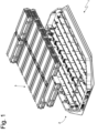
- number 1 indicates, as a whole, a power storage system of a road vehicle (in particular, a car) provided with chemical batteries.
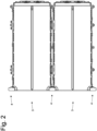
- the power storage system 1 comprises a container 2 and a plurality of battery modules 3 (in particular, fifteen battery modules 3), each arranged in the container 2, (at first) separate from and independent of the other battery modules 3 and accommodating, on the inside, a group of electrochemical cells with a parallelepiped shape (namely, having a "pouch” structure or a prismatic structure).
- the different battery modules 3 are electrically connected to one another in series by means of a plurality of electrical connectors 4.
- each electrical connector 4 connects the terminals 5 of two adjacent battery modules 3 to one another; in particular, each terminal 5 has a threaded dead hole 6 to create the mechanical connection of the corresponding electrical connector 4.
- each electrical connector 4 comprises a conductor bar 7 (usually made of copper), which is provided with two through holes 8 at the ends and is configured to be laid on the two terminals 5 of the battery modules 3. Furthermore, each electrical connector 4 comprises two screws 9, each arranged through a through hole 8 of the conductor bar 7 with a clearance and screwed (namely, configured to be screwed) into a threaded hole 7 of a corresponding terminal 5.
- each through hole 8 of the conductor bar 7 has larger dimensions than a diameter of the corresponding screw 9 so as to allow the corresponding screw 9 to move inside the through hole 8 with a given clearance, so that its position can be adjusted in order to make up for building tolerances.
- each through hole 8 of the conductor bar 7 has a longitudinal size that is greater than a transverse size (namely, each through hole 8 has an oblong shape, with the longitudinal size prevailing over the transverse size) and both the longitudinal size and the transverse size of each through hole 8 are greater than the diameter of the corresponding screw 9 so as to allow the corresponding screw 9 to move inside the through hole 8 with a given clearance both longitudinally and transversely (so that its position can be adjusted in order to make up for building tolerances).
- Each electrical connector 4 comprises a retaining sheet 10 (usually made of copper), which is laid on the conductor bar 7 and has, at the ends, two through holes 11, each aligned with a corresponding through hole 8.
- Each screw 9 is screwed into the corresponding through hole 11; namely, in order to be inserted through the corresponding through hole 11, it has to be screwed into the corresponding through hole 11; in other words, the thread of each screw 9 does not allow the screw 9 to go through the corresponding hole 11, if not through a screwing operation (namely, an outer diameter of the thread of each screw 9 is larger than a width of the corresponding through hole 11).
- each through hole 11 of the retaining sheet 10 has a longitudinal size that is greater than a transverse size (namely, each through hole 11 has an oblong shape, with the longitudinal size prevailing over the transverse size), thus reproducing the shape of the through holes 8 of the conductor bar 7.
- Each through hole 11 of the retaining sheet 10 has a longitudinal size that is greater than the outer diameter of the thread of each screw 9 and a transverse size that is (slightly) smaller than the outer diameter of the thread of each screw 9 (hence, the screw 9 has to be screwed into the through hole 11 in order to be inserted into the through hole 11).
- the two screws 9 are previously screwed into the through holes 11 of the retaining sheet 10 and this constrains the two screws 9 to the retaining sheet 10; in this way, the screws 9 (which cannot be removed from the retaining sheet 10, if not by being unscrewed through the through holes 11 of the retaining sheet 10) always remain coupled to the retaining sheet 10 and cannot get "lost" following a wrong or clumsy handling of an operator.
- Each electrical connector 4 comprises a shell 12, which is made of an electrically insulating material, is open at the top and at the bottom and contains, on the inside, the conductor bar 7; preferably (though not necessarily), each electrical connector 4 also comprises a lid 13, which is made of an electrically insulating material and is coupled to the shell 12 in order to close the shell 12 at the top.
- the shell 12 could be overmoulded around the conductor bar 7 or the conductor bar 7 could be inserted (with force) into the previously moulded shell 12 (usually through a given elastic deformation of the shell 12) .
- the retaining sheet 10 is contained (inserted, locked) inside the shell 12, so that it cannot be removed from the shell 12 once it is coupled to the screws 9; in this way, the screws 9 (which cannot be removed from the retaining sheet 10, if not by being unscrewed through the through holes 11 of the retaining sheet 10) always remain coupled to the shell 12 (hence, to the electrical connector 4) and cannot get "lost" following a wrong or clumsy handling of an operator.
- the retaining sheet 10 is contained in the shell 12, thus allowing the retaining sheet 10 to make (limited) transverse movements (namely, movements in a plane that is perpendicular to a longitudinal axis of the screws 9); in this way, the retaining sheet 10, to which the screws 9 are constrained, can (slightly) adjust its position in order to make up for building tolerances.
- the retaining sheet 10 can make (limited) transverse movements (namely, movements in a plane that is perpendicular to a longitudinal axis of the screws 9) inside the shell 12.
- the shell 12 laterally has two opposite through slits 14, through which the retaining sheet 10 can be inserted inside the shell 12 (alternatively, there could be one single through slit 14 arranged on one single side).
- the retaining sheet 10 preferably is longer than an inner space of the shell 12 so that the retaining sheet 10 can be arranged inside the shell 12 only by engaging, on both sides, the corresponding slits 14.
- a central part of the retaining sheet 10 of each electrical connector 4 has a width that is substantially the same as the width of the slits 14 (so as to substantially engage the slits 14 without a clearance), whereas, at the two ends, the retaining sheet 10 of each electrical connector 4 has two appendages 15 with a smaller width than the central part and, when the retaining sheet 10 is inserted in the shell 12, the appendages 15 of the retaining sheet 10 engage the corresponding slits 14 (namely, they are inside the corresponding slits 14).
- the through slits 14 of the shell 12 are misaligned relative to the through holes 8 of the conductor bar 7, so that, once it is inserted through a slit 14, the retaining sheet 10 has to be translated perpendicularly to the through slit 14 in order to align the through holes 11 of the retaining sheet 10 with the corresponding through holes 8 of the conductor bar 7; this translation of the retaining sheet 10 is enabled by the presence of the appendages 15 with a smaller width at the two ends of the retaining sheet 10.
- the asymmetric arrangement of the appendages 15 of the retaining sheet 10 makes sure that the retaining sheet 10 can correctly be inserted only with one single orientation (namely, if the retaining sheet 10 is inserted with a contrary, hence undesired orientation, the through holes 11 of the retaining sheet 10 cannot be aligned with the corresponding through holes 8 of the conductor bar 7).
- the shell 12 of each electrical conductor 4 comprises protuberances 16, which have an asymmetric position or conformation relative to the shell 12 and are configured to engage respective openings of the power storage system 1 only when the shell 12 has one single predetermined orientation.
- the protuberances 16 ensure that each electrical connector 4 can always be mounted in the power storage system 1 only with one single predetermined orientation, thus avoiding any kind of positioning error.
- the conductor bar 7 of each electrical connector 4 consists of a plurality of sheets 17, which are identical to one another and overlap one another; in this way, the conductor bar 7 is more flexible and, therefore, can more easily adjust to possible imperfections due to building tolerances (namely, the greater flexibility of the conductor bar 7 allows it to better make up for building tolerances).
- the sheet-like structure of the conductor bar 7 significantly increases the flexibility of the conductor bar 7, ensuring a greater ability to make up for building tolerances.
- the conductor bar 7 could consist of six-eight sheets 17 identical to one another and overlapping one another, each having a thickness of circa one millimetre.
- each screw 9 consists of a head 18 and a cylindrical body, which projects from the head 18 and has an intermediate portion 19 without thread, which is arranged in contact with the head 18, and a threaded end portion 20, which is arranged opposite the head 18; the threaded end portion 20 is screwed into a corresponding threaded hole 8 of the conductor bar 7, whereas the intermediate portion 19 without thread is on the outside of the corresponding threaded hole 8 of the conductor bar 7.
- the intermediate portion 19 without thread of each screw 9 preferably has a smaller diameter than a diameter of the threaded end portion 20, so that the intermediate portion 19 has a clearance in all directions relative to the corresponding through hole 11 of the retaining sheet 10; in other words, the threaded end portion 20 can go through the corresponding through hole 11 of the retaining sheet 10 only after a screwing, whereas the intermediate portion 19 can be "loose" inside the corresponding through hole 11 of the retaining sheet 10 with a given clearance.
- the intermediate portion 19 without thread has a length that is (at least) the same as the length of the threaded end portion 20; in this way, when the electrical connector 4 is laid on the terminals 5, both screws 9 can freely slide upwards (while waiting to be screwed into the corresponding threaded holes 6 of the terminals 5) thanks to the clearance present between each intermediate portion 19 and the corresponding through hole 11 of the retaining sheet 10, always keeping the electrical connector 4 horizontal (hence, permitting a simple and ideal screwing of the screws 9 into the corresponding threaded holes 6 of the terminals 5, without causing, during the screwing of the screws 9, any tension in the conductor bar 7 and in the terminals 5).
- the electrical connector 4 described above has numerous advantages.
- the electrical connector 4 disclosed above allows the terminals 5 of two adjacent battery modules 3 to be connected to one another creating a stable electrical connection with a low electrical resistance, even in the presence of relatively great building tolerances.
- the electrical connector 4 disclosed above ensures an electrical insulation both during mounting operations and during maintenance operations.
- the electrical connector 4 disclosed above offers to those operators who handle and install the electrical connector 4 a high degree of safety, since the screws 9 of the electrical connector 4 cannot get lost in any way; indeed, losing the screws 9 can pose a significant problem, for finding a lost screw 9 between the modules 3 is complicated (the space is very small) and dangerous (there always is the risk of accidentally touching a part under voltage).
- the electrical connector 4 disclosed above allows the terminals 5 of two adjacent battery modules 3 to be electrically connected to one another in a simple and quick fashion.
Landscapes
- Chemical & Material Sciences (AREA)
- Chemical Kinetics & Catalysis (AREA)
- Electrochemistry (AREA)
- General Chemical & Material Sciences (AREA)
- Connection Of Batteries Or Terminals (AREA)
- Connections By Means Of Piercing Elements, Nuts, Or Screws (AREA)
Applications Claiming Priority (1)
| Application Number | Priority Date | Filing Date | Title |
|---|---|---|---|
| IT102022000006839A IT202200006839A1 (it) | 2022-04-06 | 2022-04-06 | Connettore elettrico per collegare tra loro i morsetti di due moduli batteria adiacenti in un sistema di accumulo di energia elettrica |
Publications (1)
| Publication Number | Publication Date |
|---|---|
| EP4258452A1 true EP4258452A1 (fr) | 2023-10-11 |
Family
ID=82308636
Family Applications (1)
| Application Number | Title | Priority Date | Filing Date |
|---|---|---|---|
| EP23166680.1A Pending EP4258452A1 (fr) | 2022-04-06 | 2023-04-05 | Connecteur électrique pour connecter les bornes de deux modules de batterie adjacents l'un à l'autre dans un système de stockage d'énergie |
Country Status (5)
| Country | Link |
|---|---|
| US (1) | US20230327291A1 (fr) |
| EP (1) | EP4258452A1 (fr) |
| JP (1) | JP2023154413A (fr) |
| CN (1) | CN116895915A (fr) |
| IT (1) | IT202200006839A1 (fr) |
Citations (3)
| Publication number | Priority date | Publication date | Assignee | Title |
|---|---|---|---|---|
| US7667952B2 (en) | 2004-11-22 | 2010-02-23 | Semikron | Connection system between capacitor batteries |
| US20170352964A1 (en) | 2016-06-01 | 2017-12-07 | Termaco Ltee | Battery connector |
| US20180114961A1 (en) | 2016-10-21 | 2018-04-26 | Lg Chem, Ltd. | Battery pack including coupling member having assembling guide function |
-
2022
- 2022-04-06 IT IT102022000006839A patent/IT202200006839A1/it unknown
-
2023
- 2023-04-03 US US18/194,976 patent/US20230327291A1/en active Pending
- 2023-04-04 JP JP2023060516A patent/JP2023154413A/ja active Pending
- 2023-04-05 EP EP23166680.1A patent/EP4258452A1/fr active Pending
- 2023-04-06 CN CN202310362527.8A patent/CN116895915A/zh active Pending
Patent Citations (3)
| Publication number | Priority date | Publication date | Assignee | Title |
|---|---|---|---|---|
| US7667952B2 (en) | 2004-11-22 | 2010-02-23 | Semikron | Connection system between capacitor batteries |
| US20170352964A1 (en) | 2016-06-01 | 2017-12-07 | Termaco Ltee | Battery connector |
| US20180114961A1 (en) | 2016-10-21 | 2018-04-26 | Lg Chem, Ltd. | Battery pack including coupling member having assembling guide function |
Also Published As
| Publication number | Publication date |
|---|---|
| IT202200006839A1 (it) | 2023-10-06 |
| CN116895915A (zh) | 2023-10-17 |
| JP2023154413A (ja) | 2023-10-19 |
| US20230327291A1 (en) | 2023-10-12 |
Similar Documents
| Publication | Publication Date | Title |
|---|---|---|
| EP3923408B1 (fr) | Ensemble de connexion, module de batterie, bloc-batterie et dispositif faisant appel au module de batterie en tant que source d'alimentation | |
| EP2808921B1 (fr) | Module de batterie | |
| EP2793290B1 (fr) | Module de batterie | |
| CN103811706B (zh) | 汇流条模块及电源装置 | |
| EP3599652B1 (fr) | Ensemble de carte d'isolation et module de batterie | |
| JP5813430B2 (ja) | 電源体の接続部材、バスバーモジュール及び該バスバーモジュールを備えた電源装置 | |
| US8945747B2 (en) | Battery cell having an attachment structure and vehicle battery module | |
| US9893340B2 (en) | Battery wiring module | |
| EP2022110A1 (fr) | Système de batterie modulaire | |
| WO2006043163A1 (fr) | Module de batterie et ensemble batterie | |
| KR20150005990A (ko) | 전력 저장 어셈블리를 지지하는 장치 | |
| CN111149234A (zh) | 电连接部件收纳壳体以及电池模块 | |
| US9461294B2 (en) | Battery pack | |
| JP5813429B2 (ja) | 電源体の接続構造、バスバーモジュール及び該バスバーモジュールを備えた電源装置 | |
| US11862817B2 (en) | Energy storage apparatus | |
| CN113300052A (zh) | 单体连接单元及电池模块 | |
| JP2019169389A (ja) | 蓄電装置 | |
| WO2014181806A1 (fr) | Module de barres omnibus, et dispositif d'alimentation électrique | |
| US20250070426A1 (en) | Battery cell, battery, and electric apparatus | |
| JP7828545B2 (ja) | 蓄電装置 | |
| JP6370256B2 (ja) | 蓄電モジュール | |
| EP4258452A1 (fr) | Connecteur électrique pour connecter les bornes de deux modules de batterie adjacents l'un à l'autre dans un système de stockage d'énergie | |
| US11764504B2 (en) | Connector | |
| EP2581964A1 (fr) | Bloc-batteries | |
| US20240106065A1 (en) | Energy storage apparatus |
Legal Events
| Date | Code | Title | Description |
|---|---|---|---|
| PUAI | Public reference made under article 153(3) epc to a published international application that has entered the european phase |
Free format text: ORIGINAL CODE: 0009012 |
|
| STAA | Information on the status of an ep patent application or granted ep patent |
Free format text: STATUS: THE APPLICATION HAS BEEN PUBLISHED |
|
| AK | Designated contracting states |
Kind code of ref document: A1 Designated state(s): AL AT BE BG CH CY CZ DE DK EE ES FI FR GB GR HR HU IE IS IT LI LT LU LV MC ME MK MT NL NO PL PT RO RS SE SI SK SM TR |
|
| STAA | Information on the status of an ep patent application or granted ep patent |
Free format text: STATUS: REQUEST FOR EXAMINATION WAS MADE |
|
| 17P | Request for examination filed |
Effective date: 20231107 |
|
| RBV | Designated contracting states (corrected) |
Designated state(s): AL AT BE BG CH CY CZ DE DK EE ES FI FR GB GR HR HU IE IS IT LI LT LU LV MC ME MK MT NL NO PL PT RO RS SE SI SK SM TR |
|
| GRAP | Despatch of communication of intention to grant a patent |
Free format text: ORIGINAL CODE: EPIDOSNIGR1 |
|
| STAA | Information on the status of an ep patent application or granted ep patent |
Free format text: STATUS: GRANT OF PATENT IS INTENDED |
|
| INTG | Intention to grant announced |
Effective date: 20260107 |
|
| GRAS | Grant fee paid |
Free format text: ORIGINAL CODE: EPIDOSNIGR3 |
|
| GRAA | (expected) grant |
Free format text: ORIGINAL CODE: 0009210 |
|
| STAA | Information on the status of an ep patent application or granted ep patent |
Free format text: STATUS: THE PATENT HAS BEEN GRANTED |