EP4258480A1 - Antenne et système d'antennes - Google Patents
Antenne et système d'antennes Download PDFInfo
- Publication number
- EP4258480A1 EP4258480A1 EP21912451.8A EP21912451A EP4258480A1 EP 4258480 A1 EP4258480 A1 EP 4258480A1 EP 21912451 A EP21912451 A EP 21912451A EP 4258480 A1 EP4258480 A1 EP 4258480A1
- Authority
- EP
- European Patent Office
- Prior art keywords
- antenna
- metal plate
- signal
- metal plates
- antenna module
- Prior art date
- Legal status (The legal status is an assumption and is not a legal conclusion. Google has not performed a legal analysis and makes no representation as to the accuracy of the status listed.)
- Pending
Links
Images


Classifications
-
- H—ELECTRICITY
- H01—ELECTRIC ELEMENTS
- H01Q—ANTENNAS, i.e. RADIO AERIALS
- H01Q15/00—Devices for reflection, refraction, diffraction or polarisation of waves radiated from an antenna, e.g. quasi-optical devices
- H01Q15/0006—Devices acting selectively as reflecting surface, as diffracting or as refracting device, e.g. frequency filtering or angular spatial filtering devices
- H01Q15/0013—Devices acting selectively as reflecting surface, as diffracting or as refracting device, e.g. frequency filtering or angular spatial filtering devices said selective devices working as frequency-selective reflecting surfaces, e.g. FSS, dichroic plates, surfaces being partly transmissive and reflective
-
- H—ELECTRICITY
- H01—ELECTRIC ELEMENTS
- H01Q—ANTENNAS, i.e. RADIO AERIALS
- H01Q1/00—Details of, or arrangements associated with, antennas
- H01Q1/12—Supports; Mounting means
- H01Q1/22—Supports; Mounting means by structural association with other equipment or articles
- H01Q1/24—Supports; Mounting means by structural association with other equipment or articles with receiving set
- H01Q1/241—Supports; Mounting means by structural association with other equipment or articles with receiving set used in mobile communications, e.g. GSM
- H01Q1/246—Supports; Mounting means by structural association with other equipment or articles with receiving set used in mobile communications, e.g. GSM specially adapted for base stations
-
- H—ELECTRICITY
- H01—ELECTRIC ELEMENTS
- H01Q—ANTENNAS, i.e. RADIO AERIALS
- H01Q15/00—Devices for reflection, refraction, diffraction or polarisation of waves radiated from an antenna, e.g. quasi-optical devices
- H01Q15/0006—Devices acting selectively as reflecting surface, as diffracting or as refracting device, e.g. frequency filtering or angular spatial filtering devices
- H01Q15/0013—Devices acting selectively as reflecting surface, as diffracting or as refracting device, e.g. frequency filtering or angular spatial filtering devices said selective devices working as frequency-selective reflecting surfaces, e.g. FSS, dichroic plates, surfaces being partly transmissive and reflective
- H01Q15/0026—Devices acting selectively as reflecting surface, as diffracting or as refracting device, e.g. frequency filtering or angular spatial filtering devices said selective devices working as frequency-selective reflecting surfaces, e.g. FSS, dichroic plates, surfaces being partly transmissive and reflective said selective devices having a stacked geometry or having multiple layers
-
- H—ELECTRICITY
- H01—ELECTRIC ELEMENTS
- H01Q—ANTENNAS, i.e. RADIO AERIALS
- H01Q15/00—Devices for reflection, refraction, diffraction or polarisation of waves radiated from an antenna, e.g. quasi-optical devices
- H01Q15/0006—Devices acting selectively as reflecting surface, as diffracting or as refracting device, e.g. frequency filtering or angular spatial filtering devices
- H01Q15/0053—Selective devices used as spatial filter or angular sidelobe filter
-
- H—ELECTRICITY
- H01—ELECTRIC ELEMENTS
- H01Q—ANTENNAS, i.e. RADIO AERIALS
- H01Q5/00—Arrangements for simultaneous operation of antennas on two or more different wavebands, e.g. dual-band or multi-band arrangements
- H01Q5/40—Imbricated or interleaved structures; Combined or electromagnetically coupled arrangements, e.g. comprising two or more non-connected fed radiating elements
- H01Q5/42—Imbricated or interleaved structures; Combined or electromagnetically coupled arrangements, e.g. comprising two or more non-connected fed radiating elements using two or more imbricated arrays
Definitions
- This application relates to the field of wireless communication technologies, and in particular, to an antenna and an antenna system.
- a frequency selective surface (Frequency Selective Surface, FSS) structure on a radome in an antenna system is changed, to achieve different reflection and transmission effects on signals of multiple different frequency bands, and implement reflection and transmission of a multi-band electromagnetic wave.
- the FSS may meet a working requirement of a multi-band antenna
- the FSS of this design is usually a separated island structural unit, and the FSS structure usually uses a printed circuit board (Printed Circuit Board, PCB) processing technology, and therefore processing costs are high.
- PCB printed Circuit Board
- an existing high-low-frequency co-existence antenna and the FSS are usually integrated, which makes single usage scenarios of the existing high-low-frequency co-existence antenna and the FSS.
- Embodiments of this application provide an antenna and an antenna system, which can meet a working requirement of a multi-band antenna, reduce costs, and can be used for flexible and changeable usage scenarios.
- an embodiment of this application provides an antenna and an antenna system thereof.
- the antenna includes:
- signals sent or received by antenna modules belonging to different antennas are controlled by the signal control part, so that while the antenna system can meet a working requirement of a multi-band antenna, reduce costs, and can be used for flexible and changeable usage scenarios.
- the signal control part includes at least one layer of metal plates in a hollow structure, where the hollow structure is a regular figure or an irregular figure, and a single layer of a metal plate is an integration structure.
- the signals generate resonance on the signal control part, so that the first signal is reflected and the second signal is transmitted.
- the metal plates are multi-layered, multiple layers of the metal plates are arranged at relative intervals, plate surfaces of adjacent metal plates form a first space, and the adjacent metal plates at least partially overlap on an orthographic projection surface of one of the metal plates.
- the signals generate resonance on different metal plates, so that the different metal plates and spaces between the metal plates may form cascades, thereby generating multiple resonance points, and then reflecting the first signal and transmitting the second signal.
- the metal plates are multi-layered, and hollow structures of the different metal plates are the same or different.
- the adjacent metal plates include a first metal plate and a second metal plate, and the first metal plate, the second metal plate, and the first support component are an integration structure.
- the metal plates are multi-layered, at least one first support component is disposed between the adjacent metal plates, one end of the first support component is connected to one of the metal plates, and the other end of the first support component is connected to another metal plate, where the first support component is made of an insulating material. Therefore, two adjacent metal plates are fixed and avoid conduction between the two adjacent metal plates.
- the first support component is connected to a metal plate through a buckle.
- a plate surface of a metal plate is flat or curved.
- the antenna further includes: a frequency selective surface FSS, where the frequency selective surface is detachably connected to the signal control part and is located on a side away from the first antenna module.
- the signal control part may transmit the second signal and avoid reflecting the second signal.
- the frequency selective surface is connected to the signal control part through a buckle.
- the antenna feeder includes at least one of a microstrip, a coaxial line, or other feeders.
- the multiple first antenna modules are arranged in an array.
- the first antenna module is detachably connected to the signal control part through a second support component.
- each first antenna module corresponds to one second support component. Therefore, the first antenna module is fixed on the signal control part, and the first antenna module can be conveniently mounted or removed.
- both the first antenna module and the signal control part are connected to the second support component through a buckle.
- an embodiment of this application provides an antenna system, including a first antenna and a second antenna, and the first antenna and the second antenna are mounted on a same device, where the first antenna is the antenna provided by the first aspect, and the second antenna is the antenna in which the second antenna module mentioned in the antenna provided by the first aspect is located.
- antenna modules of different frequencies share a same antenna aperture surface, which has little impact on an original antenna system, and improve a capacity, an operating frequency band, spectrum resources, and the like of the original antenna system.
- the first antenna and the second antenna have different structures.
- words such as “exemplary”, “for example”, or “for example” are used to represent an example, an illustration, or a description. Any embodiment or design solution described as “exemplary”, “for example”, or “for example” in the embodiments of this application should not be interpreted as being more preferred or advantageous than another embodiment or design solution. Specifically, the use of the words such as “exemplary”, “for example”, or “for example” is intended to present related concepts in a specific manner.
- the term “and/or” is merely an association relationship for describing associated objects, and indicates that three relationships may exist.
- a and/or B may indicate: only A exists, only B exists, and both A and B exist.
- the term “multiple” means two or more.
- multiple systems refer to two or more systems
- multiple screen terminals refers to two or more screen terminals.
- the orientation or position relationship indicated by the terms “upper”, “lower”, “front”, “rear”, “inside”, “outside”, or the like is based on the orientation or position relationship shown in the accompanying drawings, and is merely for ease of describing this application and simplifying description.
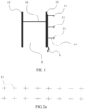
- FIG. 1 is a schematic structural diagram of an antenna according to an embodiment of this application.
- the antenna may include: a first antenna module 11, a first metal plate 12, a second metal plate 13, and a feeder network 14.
- the first metal plate 12 and the second metal plate 13 are arranged at relative intervals and fixedly connected.
- the first metal plate 12 and the second metal plate 13 may form a first space 15.
- both the first metal plate 12 and the second metal plate 13 are passive structures.
- first antenna modules 11, such as 10, 20 there may be multiple first antenna modules 11, such as 10, 20.
- the multiple first antenna modules 11 may be arranged in an array.
- the multiple first antenna modules 11 may be arranged in a 2x8 array.
- the multiple first antenna modules 11 may alternatively be arranged in a 3x5 array, or the like.
- the first antenna module 11 may be connected to the first metal plate 12 through a second support component 17.
- both the first metal plate 12 and the first antenna module 11 may be detachably connected to the second support component 17 through a buckle, a bolt, or the like.
- the second support component 17 may be made of an insulating material, and the insulating material may be plastic. It may be understood that, in this solution, the first antenna module 11 is detachably connected to the first metal plate 12, so that a quantity of the first antenna modules 11 may be increased or decreased according to a requirement, thereby improving flexibility.
- the first metal plate 12, the second metal plate 13, and a first space 15 may form a signal control part.
- the signal control part may allow a high frequency to pass through and block a low frequency, in other words, allow a high frequency signal to pass through, and block a low frequency signal from passing through.
- the signal control part may allow the low frequency to pass through and block the high frequency, to be specific, allow a low frequency signal to pass through, and block a high frequency signal from passing through. As shown in FIG.
- the first antenna module 11 sends a signal a, where the signal a may be reflected by the first metal plate 12 and propagated in a direction away from the first metal plate 12 and the second metal plate 13, in other words, propagated towards a right side in FIG. 3 .
- a second antenna module 21 sends a signal b, where the signal b may be sequentially propagated through the second metal plate 13, the first space 15, and the first metal plate 12 in a direction away from the first metal plate 12 and the second metal plate 13, in other words, propagated towards the right side in FIG. 3 .
- the first metal plate 12, the second metal plate 13, and the first space 15 may form a signal control part, which may reflect a signal sent or received by the first antenna module 11, and may transmit a signal sent or received by the second antenna module 21.
- a frequency of the signal sent or received by the second antenna module 21 is different from a frequency of the signal sent by the first antenna module 11.
- the first antenna module 11 and the second antenna module 21 belong to different antennas. It may be understood that, when the frequency of the signal sent or received by the first antenna module 11 is higher than the frequency of the signal sent or received by the second antenna module 21, the signal control part is to allow a low frequency to pass through and block a high frequency. When the frequency of the signal sent or received by the first antenna module 11 is lower than the frequency of the signal sent or received by the second antenna module 21, the signal control part is to allow a high frequency to pass through and block a low frequency.
- the first antenna module 11 and the second antenna module 21 receive signals, some signals received by the first antenna module 11 may be directly received by the first antenna module 11, and the other signals are reflected by the first metal plate 12 and then received by the first antenna module 11.
- the signals received by the second antenna module 21 may be sequentially propagated through the first metal plate 12, the first space 15, and the second metal plate 13, and received by the second antenna module 21.
- an operating frequency band is not limited to a frequency band in the example.
- S21 is a curve of a transmitted signal of a signal control part
- S 11 is a curve of a reflected signal of a signal control part.
- a frequency of the transmitted signal within an operating frequency band of 0.69 GHz to 0.96 GHz is less than -10 dB
- a frequency of the transmitted signal within an operating frequency band of 1.7 GHz to 2.2 GHz is greater than -0.5 dB
- a frequency of the reflected signal within the operating frequency band of 0.69 GHz to 0.96 GHz is greater than -0.5 dB
- the frequency of the transmitted signal within the operating frequency band of 1.7 GHz to 2.2 GHz is less than -10 dB.
- the signal control part may transmit all signals sent by the second antenna module 21 in the operating frequency band of 1.7 GHz to 2.2 GHz. In the operating frequency band of 0.69 GHz to 0.96 GHz, all signals sent by the first antenna module 11 may be reflected.
- a signal sent or received by an antenna module (such as the first antenna module 11 the second antenna module 21) generates a single resonance on the first metal plate 12 or the second metal plate 13, a first signal (such as a signal sent by the first antenna module 11) is reflected, and a second signal (such as a signal sent by the second antenna module 21) is transmitted.
- Cascading the first metal plate 12, the first space 15, and the second metal plate 13 may generate two resonance points, so that a broadband transmission may be generated at a high frequency and substantially total reflection to a low frequency, or the broadband transmission may be generated at a low frequency and substantially total reflection to a high frequency.
- the signal control part may act as allowing a high frequency to pass through and block a low frequency, or allowing a low frequency to pass through and block a high frequency.
- an antenna system can also meet a working requirement of a multi-band antenna, and can be applied to multiple application scenarios.
- both the first metal plate 12 and the second metal plate 13 have a hollow structure.
- a shape of the hollow structure may be a regular figure, or may be an irregular figure. This is not limited herein.
- a hollow structure on the first metal plate 12 is referred to as a first hollow structure 121
- a hollow structure on the second metal plate 13 is referred to as a second hollow structure 131.
- the first hollow structure 121 and the second hollow structure 131 may be the same or may be different. This is not limited herein.
- the two hollow structures do not need to be aligned in a direction of the second metal plate 13 toward the first metal plate 12, to be specific, do not need to be aligned in a direction of an arrow x in the figure, and may be placed in a misplaced position, mirror symmetry, or the like.
- the hollow structures on the first metal plate 12 and the second metal plate 13 may be one of a spiral structure, a square structure, or a circular structure. This is not limited herein. It may be understood that, in this solution, a hollow structure refers to a circular, square, or spiral permeable structure opened on a metal plate, such as a hole.
- a first support component 16 may be provided within the first space 15. There may be one or more first support components 16. One end of the first support component 16 may be connected to the first metal plate 12, and the other end of the first support component 16 may be connected to the second metal plate 13. For example, both the first metal plate 12 and the second metal plate 13 may be connected to the first support component 16 through a buckle, a bolt, or the like.
- the first support component 16 may be made of an insulating material, so as to avoid conduction between the first metal plate 12 and the second metal plate 13.
- the first support component 16 may also be made of a non-insulating material (such as a metal material).
- an area of a cross section of the first support component 16 in a plate surface direction of the first metal plate 12 may be lower than a preset area threshold.
- a preset area threshold For example, when the first support component 12 is cylindrical, its diameter may be less than a preset diameter threshold.
- first metal plate 12 and the second metal plate 13 may be designed in an integrated manner through a sheet metal technology.
- first metal plate 12, the second metal plate 13, and the first support component 16 may be an integration structure.
- the feeder network 14 may be integrated on the first metal plate 12, and the feeder network 14 may be used to excite the first antenna module 11.
- the feeder network 14 may include at least one antenna feeder.
- the antenna feeder may be a microstrip, or may be a coaxial line, or the like. This is not limited herein. It may be understood that an end away from the first metal plate 12 of the feeder network 14 may be connected to a signal transmit source of an antenna system, so that the feeder network 14 may excite the first antenna module 11.
- the feeder network 14 is integrated on the first metal plate 12, and is located on the same side of the first metal plate 12 as the first antenna module 11. It may be understood that, in this solution, the feeder network 14 is integrated on the first metal plate 12, so that design complexity is reduced, installation is simple, and processing costs are low.
- an antenna feeder is a transmission line that connects an antenna to a receiver and a transmitter to transmit radio frequency energy.
- the antenna feeder needs to have good impedance matching with the antenna, small transmission loss, a small radiation effect, a plenty of frequency bandwidth and a power capacity.
- the antenna feeder is classified into a parallel double line, a coaxial line, a microstrip, and a waveguide.
- the antenna may further include a frequency selective surface (Frequency Selective Surface, FSS).
- FSS Frequency Selective Surface
- the FSS is detachably connected to the second metal plate 13, for example, through a buckle, a bolt or the like. Therefore, when the frequency of signals sent or received by the antenna module on both sides of the signal control part formed by the first metal plate 12, the second metal plate 13, and the first space 15 are the same, the second metal plate 13 may be avoided through the FSS reflecting a signal sent or received by the antenna modules on the side of the second metal plate 13. Then, the signal transmitted or received by the antenna module on the side of the second metal plate 13 passes through the signal control part.
- FSS Frequency Selective Surface
- a resonance mode of the signal control part formed by the first metal plate 12, the first space 15, and the second metal plate 13 may be changed.
- the second metal plate 13 is a reflective resonance point
- the FSS is added
- the second metal plate 13 is switched to a transmissive resonance point.
- the second metal plate 13 is switched to a reflective resonance point.
- the frequency selective surface FSS may be of a patch type, or may be of a slot type.
- the patch type refers to periodically labeling a same metal unit on a medium surface.
- a filtering mechanism of the patch type is as follows: If it is assumed that an electromagnetic wave is incident on a patch type frequency selective surface from left to right. An electric field in the direction parallel to a patch generates a force on electronics to oscillate the electrons, therefore forming an induced current on a metal surface. At this point, part of energy of the incident electromagnetic wave is converted into kinetic energy needed to maintain a state of the electronic oscillation, while the other part of the energy continues to propagate through a metal wire. In other words, according to the law of conservation of energy, the energy maintaining the electronics moving is absorbed by the electronics.
- the patch type frequency selective surface is reflective.
- the patch is "transparent" to the incident electromagnetic wave, and the energy of the electromagnetic wave may be fully propagated.
- the patch type frequency selective surface is transmissive.
- a slot type refers to the periodically opening some metal unit slots on a metal plate.
- a filtering mechanism of the slot type is as follows: When a low frequency electromagnetic wave irradiates a slot type frequency selective surface, a large range of electronics are excited to move, so that the electronics absorb most of energy, and an induced current along a gap is very small, resulting in a relatively small transmission coefficient. As the frequency of the incident wave increases, the movement range of the electronics gradually becomes smaller, and the current flowing along the gap continues to increase, therefore the transmission coefficient is improved. When the frequency of the incident electromagnetic wave reaches a specific value, the electronics on both sides of the slot move back under an electric field vector of the incident wave, forming a large induced current around the gap.
- the moving electronics radiate the electric field in a transmission direction through the gap of a dipole slot.
- a dipole slot array has a low reflection coefficient and a high transmission coefficient.
- the signal control part mentioned in this solution is mainly used for reflecting signals transmitted or received by an antenna module in an antenna to which the signal control part belongs, and transmit signals transmitted or received by an antenna module in another antenna.
- the structure of the signal control part may be formed by a single layer of the metal plate having a hollow structure, or may be formed by three or more layers of the metal plate having a hollow structure.
- a space (such as the first space 15) is formed between plate surfaces of adjacent metal plates. The adjacent metal plates overlap at least partially on an orthographic projection surface of one of the metal plates. For example, continuing to refer to FIG.
- two adjacent metal plates in a direction of an arrow x in the figure do not need to be aligned, and may be placed in a misplaced position, mirror symmetry, or the like.
- the hollow structure on a multi-layer metal plate may be the same or different. This is not limited herein.
- two adjacent metal plates may be fixed through the first support component 16 described above, or may be fixed in another manner, for example, different metal plates are sequentially fixed on a radome, a pole of an antenna or the like.
- a plate surface of the metal plate included in the signal control part may be flat or curved. This is not limited herein.
- the frequency selective surface of the antenna may be detachably connected to a metal plate farthest from the first antenna module in the signal control part.
- the frequency selective surface is located on a side away from the first antenna module on the signal control part.
- each layer of the metal plate in the signal control part is an integrated design, to be specific, each layer of the metal plate is an integrated plate, and no island structure may exist on the metal plate.
- the signal control part and the first antenna module may be directly connected, or may be indirectly connected. This is not limited herein.
- the antenna provided by this solution controls the signals sent or received by the antenna modules belonging to different antennas via the signal control part, so that while the antenna system can meet a working requirement of a multi-band antenna, reduce costs, and can be used for flexible and changeable usage scenarios.
- FIG. 7 is a schematic structural diagram of an antenna system according to an embodiment of this application.
- the antenna system includes a first antenna 71 and a second antenna 72.
- the first antenna 71 and the second antenna 72 may be mounted on a same device, to be specific, may share one mounting space, for example, share a pole of an antenna system.
- the first antenna 71 and the second antenna 72 may also share one antenna aperture surface.
- the first antenna 71 is an antenna in embodiment one above, and structures of the first antenna 71 and the second antenna 72 may be different or the same.
- the second antenna 72 may be an antenna on which the second antenna module 21 mentioned in embodiment one above is located.
- the first antenna 71 may be fixed on a radome of the second antenna 72.
- a third antenna module 721 in the second antenna 72 may be connected to the second metal plate 13 in the first antenna 71 through a buckle, a bolt, or the like.
- the multiple third antenna modules 721 may be arranged in an array manner.
- a specific arrangement manner may refer to the description about the first antenna module 11 above, and details are not described herein again.
- a fourth antenna module 722 may also be added to the second antenna 72, so as to further increase a capacity, an operating frequency band, a spectrum resource, and the like of the antenna system.
- a frequency of a signal sent or received by the fourth antenna module 722 is the same as a frequency of a signal sent or received by the antenna module in the first antenna 71, where a frequency selective surface is disposed on a side of the second metal plate 13 in the first antenna 71 facing the fourth antenna module 722.
- the multiple fourth antenna modules 722 may be arranged in an array manner.
- a specific arrangement manner may refer to the description about the first antenna module 11 above, and details are not described herein again.
- both the first antenna 71 and the second antenna 72 may be fixed on the antenna mast 73.
- a curve 81 in the figure represents an antenna radiation direction of the antenna system when the first antenna 71 is not added
- a curve 82 represents an antenna radiation direction of the antenna system after the first antenna 71 is added. It can be learned from FIG. 8 that, in the operating frequency bands of 1.74 GHz, 1.84 GHz, 1.95 GHz, and 2.14 GHz, adding the first antenna 71 has little impact on the original antenna system.
- the antenna in embodiment one is combined with other antennas, so that antenna modules of different frequencies may share a same antenna aperture surface, and the impact on the original antenna system is relatively small.
- a capacity, an operating frequency band, a spectrum resource, and the like of the original antenna system are improved.
Landscapes
- Physics & Mathematics (AREA)
- Electromagnetism (AREA)
- Engineering & Computer Science (AREA)
- Computer Networks & Wireless Communication (AREA)
- Aerials With Secondary Devices (AREA)
- Variable-Direction Aerials And Aerial Arrays (AREA)
Applications Claiming Priority (2)
| Application Number | Priority Date | Filing Date | Title |
|---|---|---|---|
| CN2020140503 | 2020-12-29 | ||
| PCT/CN2021/071502 WO2022141668A1 (fr) | 2020-12-29 | 2021-01-13 | Antenne et système d'antennes |
Publications (2)
| Publication Number | Publication Date |
|---|---|
| EP4258480A1 true EP4258480A1 (fr) | 2023-10-11 |
| EP4258480A4 EP4258480A4 (fr) | 2024-05-22 |
Family
ID=82258903
Family Applications (1)
| Application Number | Title | Priority Date | Filing Date |
|---|---|---|---|
| EP21912451.8A Pending EP4258480A4 (fr) | 2020-12-29 | 2021-01-13 | Antenne et système d'antennes |
Country Status (4)
| Country | Link |
|---|---|
| US (1) | US12388167B2 (fr) |
| EP (1) | EP4258480A4 (fr) |
| CN (1) | CN116802938A (fr) |
| WO (1) | WO2022141668A1 (fr) |
Families Citing this family (2)
| Publication number | Priority date | Publication date | Assignee | Title |
|---|---|---|---|---|
| KR102558331B1 (ko) * | 2021-12-16 | 2023-07-21 | 주식회사 에이스테크놀로지 | 선택적 차폐면을 이용한 다중 대역 기지국 안테나 |
| CN216529368U (zh) * | 2021-12-23 | 2022-05-13 | 苏州科瓴精密机械科技有限公司 | 割草机用信号增强装置及割草机 |
Family Cites Families (10)
| Publication number | Priority date | Publication date | Assignee | Title |
|---|---|---|---|---|
| US2972743A (en) * | 1957-06-19 | 1961-02-21 | Westinghouse Electric Corp | Combined infrared-radar antenna |
| US5949387A (en) | 1997-04-29 | 1999-09-07 | Trw Inc. | Frequency selective surface (FSS) filter for an antenna |
| JPWO2017056437A1 (ja) * | 2015-09-29 | 2018-07-19 | 日本電気株式会社 | マルチバンドアンテナおよび無線通信装置 |
| CN114171934B (zh) | 2017-01-24 | 2025-10-17 | 户外无线网络有限公司 | 基站天线单元及用于安装基站天线单元的方法 |
| CN108615976B (zh) * | 2018-06-15 | 2020-12-08 | 西安电子科技大学 | 基于雷达罩的双通带/宽阻带可重构频率选择表面 |
| CN109149099A (zh) | 2018-07-31 | 2019-01-04 | 电子科技大学 | 一种宽带频率可重构fss天线罩 |
| US11532890B2 (en) * | 2018-12-31 | 2022-12-20 | Hughes Network Systems, Llc | Frequency selective surface zoning technique to reduce the complication in design from large range of illumination incident angles |
| CN110416739B (zh) * | 2019-08-05 | 2021-09-28 | Oppo广东移动通信有限公司 | 壳体组件及移动终端 |
| KR102129386B1 (ko) * | 2019-09-16 | 2020-07-02 | 충북대학교 산학협력단 | 고 정전용량의 나선형 주파수선택표면을 이용한 초광대역 전파흡수체 |
| CN111555037B (zh) * | 2020-05-19 | 2021-03-30 | 中国人民解放军空军工程大学 | 一种具有极化选择特性的时域开关调控频率选择表面 |
-
2021
- 2021-01-13 EP EP21912451.8A patent/EP4258480A4/fr active Pending
- 2021-01-13 CN CN202180086661.9A patent/CN116802938A/zh active Pending
- 2021-01-13 WO PCT/CN2021/071502 patent/WO2022141668A1/fr not_active Ceased
-
2023
- 2023-06-28 US US18/343,084 patent/US12388167B2/en active Active
Also Published As
| Publication number | Publication date |
|---|---|
| US20230335903A1 (en) | 2023-10-19 |
| EP4258480A4 (fr) | 2024-05-22 |
| CN116802938A (zh) | 2023-09-22 |
| US12388167B2 (en) | 2025-08-12 |
| WO2022141668A1 (fr) | 2022-07-07 |
Similar Documents
| Publication | Publication Date | Title |
|---|---|---|
| EP3621156B1 (fr) | Antenne et dispositif de communication sans fil comprenant une antenne | |
| EP3723191B1 (fr) | Ensemble antenne et appareil électronique | |
| US12388167B2 (en) | Antenna and antenna system | |
| US11201394B2 (en) | Antenna device and electronic device | |
| CN101800356B (zh) | 共形有源相控阵天线单元 | |
| CN112751193A (zh) | 天线模组及电子设备 | |
| CN111786091B (zh) | 一种天线模组和终端 | |
| US11962092B2 (en) | Antenna module and electronic device | |
| EP3916908A1 (fr) | Antenne de communication et son unité de rayonnement | |
| JP2001127523A (ja) | レドーム付きマイクロストリップアレーアンテナ | |
| CN215497084U (zh) | 一种一体化天线装置 | |
| WO2013086835A1 (fr) | Appareil à antenne, dispositif et appareil d'émission de signal | |
| US11258167B1 (en) | Embedded antennas in aerostructures and electrically short conformal antennas | |
| US8089415B1 (en) | Multiband radar feed system and method | |
| WO2021218800A1 (fr) | Dispositif électronique | |
| CN112787080B (zh) | 天线模组及电子设备 | |
| CN216251089U (zh) | 一种毫米波射频模组加载超材料结构的组合天线及终端 | |
| CN112310655A (zh) | 电子设备 | |
| KR102127129B1 (ko) | 고 지향성 마이크로스트립 패치 안테나 장치 | |
| CN113363688A (zh) | 用于微波驱动离子的近场微波转换装置及方法 | |
| CN221080382U (zh) | 一体化基站天线 | |
| CN117317614A (zh) | 一体化基站天线 | |
| EP3883059B1 (fr) | Antenne, dispositif hyperfréquence et système de communication | |
| CN112310653A (zh) | 电子设备 | |
| EP4030560A1 (fr) | Antenne directionnelle et dispositif de communication |
Legal Events
| Date | Code | Title | Description |
|---|---|---|---|
| STAA | Information on the status of an ep patent application or granted ep patent |
Free format text: STATUS: THE INTERNATIONAL PUBLICATION HAS BEEN MADE |
|
| PUAI | Public reference made under article 153(3) epc to a published international application that has entered the european phase |
Free format text: ORIGINAL CODE: 0009012 |
|
| STAA | Information on the status of an ep patent application or granted ep patent |
Free format text: STATUS: REQUEST FOR EXAMINATION WAS MADE |
|
| 17P | Request for examination filed |
Effective date: 20230704 |
|
| AK | Designated contracting states |
Kind code of ref document: A1 Designated state(s): AL AT BE BG CH CY CZ DE DK EE ES FI FR GB GR HR HU IE IS IT LI LT LU LV MC MK MT NL NO PL PT RO RS SE SI SK SM TR |
|
| DAV | Request for validation of the european patent (deleted) | ||
| DAX | Request for extension of the european patent (deleted) | ||
| A4 | Supplementary search report drawn up and despatched |
Effective date: 20240418 |
|
| RIC1 | Information provided on ipc code assigned before grant |
Ipc: H01Q 21/00 20060101ALI20240412BHEP Ipc: H01Q 15/00 20060101AFI20240412BHEP |