EP4258568A2 - Dispositif initiateur, dispositif répondeur et système - Google Patents
Dispositif initiateur, dispositif répondeur et système Download PDFInfo
- Publication number
- EP4258568A2 EP4258568A2 EP23188843.9A EP23188843A EP4258568A2 EP 4258568 A2 EP4258568 A2 EP 4258568A2 EP 23188843 A EP23188843 A EP 23188843A EP 4258568 A2 EP4258568 A2 EP 4258568A2
- Authority
- EP
- European Patent Office
- Prior art keywords
- mimo
- responder
- initiator
- reciprocal
- training
- Prior art date
- Legal status (The legal status is an assumption and is not a legal conclusion. Google has not performed a legal analysis and makes no representation as to the accuracy of the status listed.)
- Withdrawn
Links
Images


Classifications
-
- H—ELECTRICITY
- H04—ELECTRIC COMMUNICATION TECHNIQUE
- H04B—TRANSMISSION
- H04B1/00—Details of transmission systems, not covered by a single one of groups H04B3/00 - H04B13/00; Details of transmission systems not characterised by the medium used for transmission
- H04B1/38—Transceivers, i.e. devices in which transmitter and receiver form a structural unit and in which at least one part is used for functions of transmitting and receiving
-
- H—ELECTRICITY
- H04—ELECTRIC COMMUNICATION TECHNIQUE
- H04B—TRANSMISSION
- H04B7/00—Radio transmission systems, i.e. using radiation field
- H04B7/02—Diversity systems; Multi-antenna system, i.e. transmission or reception using multiple antennas
- H04B7/04—Diversity systems; Multi-antenna system, i.e. transmission or reception using multiple antennas using two or more spaced independent antennas
- H04B7/06—Diversity systems; Multi-antenna system, i.e. transmission or reception using multiple antennas using two or more spaced independent antennas at the transmitting station
- H04B7/0686—Hybrid systems, i.e. switching and simultaneous transmission
- H04B7/0695—Hybrid systems, i.e. switching and simultaneous transmission using beam selection
- H04B7/06952—Selecting one or more beams from a plurality of beams, e.g. beam training, management or sweeping
- H04B7/06958—Multistage beam selection, e.g. beam refinement
-
- H—ELECTRICITY
- H04—ELECTRIC COMMUNICATION TECHNIQUE
- H04B—TRANSMISSION
- H04B7/00—Radio transmission systems, i.e. using radiation field
- H04B7/02—Diversity systems; Multi-antenna system, i.e. transmission or reception using multiple antennas
- H04B7/04—Diversity systems; Multi-antenna system, i.e. transmission or reception using multiple antennas using two or more spaced independent antennas
- H04B7/0413—MIMO systems
- H04B7/0417—Feedback systems
-
- H—ELECTRICITY
- H04—ELECTRIC COMMUNICATION TECHNIQUE
- H04B—TRANSMISSION
- H04B7/00—Radio transmission systems, i.e. using radiation field
- H04B7/02—Diversity systems; Multi-antenna system, i.e. transmission or reception using multiple antennas
- H04B7/04—Diversity systems; Multi-antenna system, i.e. transmission or reception using multiple antennas using two or more spaced independent antennas
- H04B7/0408—Diversity systems; Multi-antenna system, i.e. transmission or reception using multiple antennas using two or more spaced independent antennas using two or more beams, i.e. beam diversity
-
- H—ELECTRICITY
- H04—ELECTRIC COMMUNICATION TECHNIQUE
- H04B—TRANSMISSION
- H04B7/00—Radio transmission systems, i.e. using radiation field
- H04B7/02—Diversity systems; Multi-antenna system, i.e. transmission or reception using multiple antennas
- H04B7/04—Diversity systems; Multi-antenna system, i.e. transmission or reception using multiple antennas using two or more spaced independent antennas
- H04B7/0413—MIMO systems
- H04B7/0456—Selection of precoding matrices or codebooks, e.g. using matrices antenna weighting
-
- H—ELECTRICITY
- H04—ELECTRIC COMMUNICATION TECHNIQUE
- H04B—TRANSMISSION
- H04B7/00—Radio transmission systems, i.e. using radiation field
- H04B7/02—Diversity systems; Multi-antenna system, i.e. transmission or reception using multiple antennas
- H04B7/04—Diversity systems; Multi-antenna system, i.e. transmission or reception using multiple antennas using two or more spaced independent antennas
- H04B7/06—Diversity systems; Multi-antenna system, i.e. transmission or reception using multiple antennas using two or more spaced independent antennas at the transmitting station
- H04B7/0613—Diversity systems; Multi-antenna system, i.e. transmission or reception using multiple antennas using two or more spaced independent antennas at the transmitting station using simultaneous transmission
- H04B7/0615—Diversity systems; Multi-antenna system, i.e. transmission or reception using multiple antennas using two or more spaced independent antennas at the transmitting station using simultaneous transmission of weighted versions of same signal
- H04B7/0617—Diversity systems; Multi-antenna system, i.e. transmission or reception using multiple antennas using two or more spaced independent antennas at the transmitting station using simultaneous transmission of weighted versions of same signal for beam forming
-
- H—ELECTRICITY
- H04—ELECTRIC COMMUNICATION TECHNIQUE
- H04B—TRANSMISSION
- H04B7/00—Radio transmission systems, i.e. using radiation field
- H04B7/02—Diversity systems; Multi-antenna system, i.e. transmission or reception using multiple antennas
- H04B7/04—Diversity systems; Multi-antenna system, i.e. transmission or reception using multiple antennas using two or more spaced independent antennas
- H04B7/06—Diversity systems; Multi-antenna system, i.e. transmission or reception using multiple antennas using two or more spaced independent antennas at the transmitting station
- H04B7/0613—Diversity systems; Multi-antenna system, i.e. transmission or reception using multiple antennas using two or more spaced independent antennas at the transmitting station using simultaneous transmission
- H04B7/0615—Diversity systems; Multi-antenna system, i.e. transmission or reception using multiple antennas using two or more spaced independent antennas at the transmitting station using simultaneous transmission of weighted versions of same signal
- H04B7/0619—Diversity systems; Multi-antenna system, i.e. transmission or reception using multiple antennas using two or more spaced independent antennas at the transmitting station using simultaneous transmission of weighted versions of same signal using feedback from receiving side
- H04B7/0621—Feedback content
- H04B7/0632—Channel quality parameters, e.g. channel quality indicator [CQI]
-
- H—ELECTRICITY
- H04—ELECTRIC COMMUNICATION TECHNIQUE
- H04B—TRANSMISSION
- H04B7/00—Radio transmission systems, i.e. using radiation field
- H04B7/02—Diversity systems; Multi-antenna system, i.e. transmission or reception using multiple antennas
- H04B7/04—Diversity systems; Multi-antenna system, i.e. transmission or reception using multiple antennas using two or more spaced independent antennas
- H04B7/06—Diversity systems; Multi-antenna system, i.e. transmission or reception using multiple antennas using two or more spaced independent antennas at the transmitting station
- H04B7/0613—Diversity systems; Multi-antenna system, i.e. transmission or reception using multiple antennas using two or more spaced independent antennas at the transmitting station using simultaneous transmission
- H04B7/0682—Diversity systems; Multi-antenna system, i.e. transmission or reception using multiple antennas using two or more spaced independent antennas at the transmitting station using simultaneous transmission using phase diversity (e.g. phase sweeping)
-
- H—ELECTRICITY
- H04—ELECTRIC COMMUNICATION TECHNIQUE
- H04B—TRANSMISSION
- H04B7/00—Radio transmission systems, i.e. using radiation field
- H04B7/02—Diversity systems; Multi-antenna system, i.e. transmission or reception using multiple antennas
- H04B7/04—Diversity systems; Multi-antenna system, i.e. transmission or reception using multiple antennas using two or more spaced independent antennas
- H04B7/06—Diversity systems; Multi-antenna system, i.e. transmission or reception using multiple antennas using two or more spaced independent antennas at the transmitting station
- H04B7/0686—Hybrid systems, i.e. switching and simultaneous transmission
-
- H—ELECTRICITY
- H04—ELECTRIC COMMUNICATION TECHNIQUE
- H04B—TRANSMISSION
- H04B7/00—Radio transmission systems, i.e. using radiation field
- H04B7/02—Diversity systems; Multi-antenna system, i.e. transmission or reception using multiple antennas
- H04B7/04—Diversity systems; Multi-antenna system, i.e. transmission or reception using multiple antennas using two or more spaced independent antennas
- H04B7/08—Diversity systems; Multi-antenna system, i.e. transmission or reception using multiple antennas using two or more spaced independent antennas at the receiving station
- H04B7/0868—Hybrid systems, i.e. switching and combining
- H04B7/088—Hybrid systems, i.e. switching and combining using beam selection
Definitions
- the present disclosure relates to an initiator device, a responder device, and a system.
- the unlicensed 60 GHz millimeter wave (mmW) network has been attracting a growing interest.
- the WirelessHD technology is the first 60 GHz mmW industry standard that enables multi-gigabit wireless streaming of high-definition audio, video, and data among home electronic appliances, personal computers, and mobile products.
- Another multi-gigabit wireless communication technology that operates via a 60 GHz mmW frequency band is the WiGig technology standardized as the IEEE 802.11ad standard by Institute of Electrical and Electronic Engineers (IEEE). With a broad channel bandwidth of 2.16 GHz, the WiGig technology realizes a physical layer (PHY) data transfer speed of up to 6.7 gigabits per second (Gbps).
- PHY physical layer
- the IEEE 802.11 Working Group is developing an 802.11ay wireless interface as a next-generation WiGig technology capable of supporting a PHY data transfer speed higher than 100 Gbps.
- the single user (SU)-multiple input multiple output (MIMO) technique in which plural spatial streams are simultaneously transmitted through plural spatial paths, is one of major techniques for 802.11 ay.
- BF beamforming
- a signal wavelength is smaller than a normal size of an object in a propagation environment, and thus beam-like propagation with discrete spatial signal paths spreads.
- a signal quality for example, a signal-to-noise ratio (SNR) can be significantly improved in a case where both a transmit (TX) antenna beam and a receive (RX) antenna beam match a strong spatial signal path.
- TX transmit
- RX receive
- An initiator device is a device that supports a single user (SU)-multiple input multiple output (MIMO) operation, including: a generation circuit that generates a first signal including a value indicating which of a reciprocal MIMO phase and a non-reciprocal MIMO phase is applied to SU-MIMO beamforming (BF) training; and a transmission circuit that transmits the first signal to a responder device.
- SU single user
- MIMO multiple input multiple output
- a responder device is a device that supports a single user (SU)-multiple input multiple output (MIMO) operation, including: a reception circuit that receives from an initiator device a first signal including a value indicating which of a reciprocal MIMO phase and a non-reciprocal MIMO phase is applied to SU-MIMO beamforming (BF) training; and a processing circuit that determines, on the basis of the value, which of the reciprocal MIMO phase and the non-reciprocal MIMO phase is applied to the SU-MIMO BF training.
- SU single user
- MIMO multiple input multiple output
- a system includes: an initiator device and a responder device that support a single user (SU)-multiple input multiple output (MIMO) operation, in which the initiator device includes a generation circuit that generates a first signal including a value indicating which of a reciprocal MIMO phase and a non-reciprocal MIMO phase is applied to SU-MIMO beamforming (BF) training, and a transmission circuit that transmits the first signal to the responder device, and in which the responder device includes a reception circuit that receives the first signal from the initiator device, and a processing circuit that determines, on the basis of the value, which of the reciprocal MIMO phase and the non-reciprocal MIMO phase is applied to the SU-MIMO BF training.
- SU single user
- MIMO multiple input multiple output
- these comprehensive or specific aspects may be realized by a system, an apparatus, a method, an integrated circuit, a computer program, or a recording medium, and/or may be realized by an optional combination of a system, an apparatus, a method, an integrated circuit, a computer program, and a recording medium.
- WLAN wireless local area network
- FIG 1 illustrates an SU-MIMO operation in wireless system 100 (a system).
- Wireless system 100 includes initiator 102 and responder 104.
- Initiator 102 and responder 104 each include plural array antennas.
- the plural array antennas support a single user (SU)-multiple input multiple output (MIMO) operation using plural spatial streams configured to form one antenna beam/sector for each array antenna.
- a sector is one of configurations for directional control and is referred to by using a sector ID defined in the 802.11ay standard.
- a sector may be read as an antenna weighting vector (AWV).
- An AWV may be used in the case of performing signaling (feedback) in which the correspondence with a sector ID is not fixed, for example, like an AWV used in the third TRN subfield of a BRP frame, which will be described below.
- analog beamforming training (SU-MIMO BF training) is applied to the plural array antennas of initiator 102 and responder 104 to determine recommended TX/RX sector combinations (for example, best TX/RX sector combinations) for transmitting plural spatial streams.
- TX/RX sector combinations mean a TX sector combination of initiator 102 and a (best) RX sector combination of responder 104 for an initiator link in which initiator 102 performs transmission and responder 104 performs reception.
- TX/RX sector combinations mean a TX sector combination of responder 104 and a (best) RX sector combination of initiator 102 for a responder link in which responder 104 performs transmission and initiator 102 performs reception.
- TX antennas and RX antennas are capable of forming, in each array antenna, one TX sector and one RX sector, respectively.
- recommended TX/RX sector combinations for MIMO transmission each belong to a specific TX/RX antenna pair.
- all TX/RX antenna pairs to which the recommended TX/RX sector combinations belong do not overlap in the meaning that any TX antenna or any RX antenna belongs only to a single TX/RX antenna pair. This is because, in a case where there is an overlap among the TX/RX antenna pairs, a certain TX antenna or RX antenna is not involved in an SU-MIMO operation. In this case, the maximum number of spatial streams that is equal to the minimum number of TX antennas and RX antennas cannot be supported.
- TX antennas TX1 and TX2 belong to one TX/RX antenna pair TX1-RX2 and one TX/RX antenna pair TX2-RX1, respectively.
- RX antennas RX1 and RX2 belong to one TX/RX antenna pair TX2-RX1 and one TX/RX antenna pair TX1-RX2, respectively.
- the number of two MIMO streams equal to the maximum number of spatial streams, that is, the minimum number of TX antennas and RX antennas, is supported.
- TX/RX antenna pairs Number of MIMO streams supported (TX1-RX2, TX2-RX1) 2 (TX1-RX1, TX1-RX2) 1 (TX1-RX1, TX2-RX1) 1
- TX antenna TX1 belongs to both two TX/RX antenna pairs TX1-RX1 and TX1-RX2.
- the two TX/RX antenna pairs TX1-RX1 and TX1-RX2 overlap, and the other TX antenna TX2 is not involved in an SU-MIMO operation.
- the number of one MIMO stream smaller than two equal to the maximum number of spatial streams, that is, the minimum number of TX antennas and RX antennas, is supported.
- TX antenna settings and corresponding RX antenna settings can be determined for simultaneous transmission of plural spatial streams from initiator 102 to responder 104 or from responder 104 to initiator 102.
- the SU-MIMO BF training makes it possible to perform a transmission BF operation and a reception BF operation between initiator 102 and responder 104.
- a single spatial stream is transmitted between initiator 102 and responder 104 via plural antennas that use the determined TX antenna settings.
- a single spatial stream is received via plural antennas that use the determined corresponding RX antenna settings.
- the SU-MIMO BF training is formed of two consecutive phases, a single input single output (SISO) phase and a MIMO phase.
- SISO phase aims at collecting, by initiator 102, feedback from responder 104 on initiator transmit sector sweep executed last during or before the SISO phase, and collecting, by responder 104, feedback from initiator 102 on the last responder transmit sector sweep.
- the MIMO phase aims at training TX/RX sectors and TX/RX antennas to determine recommended TX/RX sector combinations and TX/RX antenna combinations for an SU-MIMO operation.
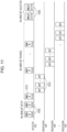
- FIG 2 illustrates a non-reciprocal MIMO phase of SU-MIMO BF training.
- a MIMO phase (non-reciprocal MIMO phase) of 802.11ay SU-MIMO BF training is formed of four subphases, an SU-MIMO BF setup subphase, an initiator SU-MIMO BF training (I-SMBT) subphase, a responder SMBT (R-SMBT) subphase, and an SU-MIMO BF feedback subphase.
- I-SMBT initiator SU-MIMO BF training
- R-SMBT responder SMBT
- initiator 102 first transmits MIMO BF setup frame 202 to responder 104.
- a frame is an example of a signal.
- MIMO BF setup frame 202 includes setting information to be used by responder 104 in the R-SMBT subphase.
- MIMO BF setup frame 202 indicates the number N tsc(I) of TX sector combinations requested for an initiator link and the number of TRN subfields requested for RX AWV training in the subsequent R-SMBT subphase.
- initiator 102 is capable of selecting a subset of candidate TX sectors for each antenna to reduce the time required for training of I-SMBT.
- the subset of candidate TX sectors for each antenna selected by initiator 102 for the I-SMBT subphase can be used to reduce the number of TRN subfields to be used for RX AWV training in the subsequent R-SMBT subphase.
- MIMO BF setup frame 204 includes setting information to be used by initiator 102 in the I-SMBT subphase.
- MIMO BF setup frame 204 indicates the number N tsc(R) of TX sector combinations requested for a responder link and the number of TRN subfields requested for RX AWV training in the subsequent I-SMBT subphase.
- responder 104 is capable of selecting a subset of candidate TX sectors for each antenna to reduce the time required for training of R-SMBT.
- the subset of candidate TX sectors for each antenna selected by responder 104 for the R-SMBT subphase can be used to reduce the number of TRN subfields required for RX AWV training in the subsequent I-SMBT subphase.
- initiator 102 After receiving MIMO BF setup frame 204 from responder 104, initiator 102 starts the initiator SMBT (I-SMBT) subphase. In the I-SMBT subphase, initiator 102 performs initiator SU-MIMO BF training. Initiator 102 transmits EDMG BRP-RX/TX packets 210 to responder 104 via plural TX antennas.
- I-SMBT initiator SMBT
- EDMG BRP-RX/TX packets 210 each include plural TRN subfields transmitted for responder 104 to perform training of receive sectors and AWVs.
- Responder 104 receives EDMG BRP-RX/TX packets 210 while switching the receive sectors and receive AWVs, thereby being capable of performing training of the receive sectors and AWVs.
- Initiator 102 transmits EDMG BRP-RX/TX packets 210 while switching transmit sectors, thereby being capable of performing training of the transmit sectors. That is, EDMG BRP-RX/TX packets 210 are packets for evaluating (training) combinations of TX sectors of the initiator and RX sectors and AWVs of the responder.
- the number of TRN subfields of each EDMG BRP-RX/TX packet 210 is configured in accordance with TRN configuration information in MIMO BF setup frame 204 received from responder 104.
- Responder 104 receives EDMG BRP-RX/TX packets 210 via plural RX antennas and trains different TX/RX sector combinations for the initiator link.
- responder 104 After receiving last EDMG BRP-RX/TX packet 212 from initiator 102, responder 104 starts the responder SMBT (R-SMBT) subphase. In the R-SMBT subphase, responder 104 transmits EDMG BRP-RX/TX packets 220 to initiator 102 via plural TX antennas.
- R-SMBT responder SMBT
- EDMG BRP-RX/TX packets 220 are packets similar to EDMG BRP-RX/TX packets 210 described above except that initiator 102 and responder 104 are replaced with responder 104 and initiator 102, respectively.
- the number of TRN subfields of each EDMG BRP-RX/TX packet 220 is configured in accordance with TRN configuration information in MIMO BF setup frame 202 received from initiator 102 in the SU-MIMO BF setup subphase.
- Initiator 102 receives EDMG BRP-RX/TX packets 220 via plural RX antennas and trains different TX/RX sector combinations for the responder link.
- initiator 102 starts the SU-MIMO BF feedback subphase.
- initiator 102 transmits MIMO BF feedback frame 232 to responder 104.
- MIMO BF feedback frame 232 indicates N tsc(R) recommended (for example, best) TX sector combinations for the responder link that are determined on the basis of channel measurement data acquired from the R-SMBT subphase.
- the responder link is a link from responder 104 to initiator 102.
- MIMO BF feedback frame 232 includes the SNRs corresponding to the N tsc(R) recommended TX sector combinations.
- MIMO BF feedback frame 232 is capable of including channel measurement results corresponding to the N tsc(R) recommended TX sector combinations.
- responder 104 transmits MIMO BF feedback frame 234 to initiator 102.
- MIMO BF feedback frame 234 indicates N tsc(I) recommended (for example, best) TX sector combinations for the initiator link that are determined on the basis of channel measurement data acquired from the I-SMBT subphase.
- the initiator link is a link from initiator 102 to responder 104.
- MIMO BF feedback frame 234 includes the SNRs corresponding to the N tsc(I) recommended TX sector combinations.
- MIMO BF feedback frame 234 includes channel measurement results corresponding to the N tsc(I) recommended TX sector combinations.
- N tsc(I) recommended TX sector combinations (or equivalent N tsc(I) recommended TX-RX AWV configurations) for the initiator link and N tsc(R) recommended TX sector combinations (or equivalent N tsc(R) recommended TX-RX AWV configurations) for the responder link are determined by using a method in which TX or RX AWVs are not derived from the same antenna.
- Initiator 102 and responder 104 need to train all combinations of TX/RX sectors, and the execution of SU-MIMO BF training requires a long time.
- the present disclosure has been conceived to reduce the time required for SU-MIMO BF training.
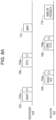
- FIG 3A is a schematic configuration diagram of STA 800 according to the present disclosure.
- FIG 3B is a detailed configuration diagram of STA 800 according to the present disclosure.
- STA 800 is an example of initiator 102 or responder 104 according to the present disclosure.
- STA 800 includes transmission signal generation circuit 810 (a generation circuit), transceiver 820 (a transmission circuit and/or a reception circuit), received signal processing circuit 830 (a processing circuit), and control circuit 840.
- transmission signal generation circuit 810, received signal processing circuit 830, and control circuit 840 may be packaged as a MAC processing circuit.
- Transmission signal generation circuit 810 generates a transmission signal.
- Transmission signal generation circuit 810 includes message generation circuit 812.
- Message generation circuit 812 generates a signal under control by control circuit 840.
- the signal is a data signal or a control signal and is, for example, a packet or a frame.
- the data signal and control signal that are generated are, for example, a MIMO BF setup frame, a BRP frame, and a MIMO BF feedback frame.
- Transceiver 820 transmits a generated signal.
- transceiver 820 receives a radio signal.
- Transceiver 820 includes PHY processing circuit 822 and plural antennas 824.
- PHY processing circuit 822 performs PHY processing on a signal generated by message generation circuit 812. The signal that has been subjected to PHY processing is converted from a baseband signal into a radio frequency signal and is transmitted via plural antennas 824.
- Received signal processing circuit 830 processes a received signal.
- Received signal processing circuit 830 includes message processing circuit 832.
- Message processing circuit 832 processes (analyzes) a received signal under control by control circuit 840 and provides the signal to control circuit 840.
- the received signal is a data signal or a control signal and is, for example, a packet or a frame.
- Control circuit 840 is a PHY and media access control (MAC) protocol controller and controls an entire PHY and MAC protocol operation.
- Control circuit 840 includes BF control circuit 842 that controls analog BF and hybrid BF operations according to the present disclosure (for example, SU-MIMO BF training and the subsequent digital BF procedure).
- BF control circuit 842 determines TX sectors and RX sectors (recommended TX sectors and RX sectors) to be used for MIMO transmission by STA 800.
- FIG 4 illustrates an example of a format of an action field of a MIMO BF setup frame according to Embodiment 1.
- the MIMO BF setup frame includes, as a part of the action field, a MIMO setup control element as the fourth piece of information.
- FIG 5 illustrates an example of a format of MIMO setup control element 400 according to Embodiment 1.
- MIMO setup control element 400 is used to convey configuration information about SU-MIMO BF training and feedback subphases or MU-MIMO BF training and feedback subphases.
- MIMO setup control element 400 includes an SU/MU field, a non-reciprocal/reciprocal SU-MIMO phase field, a DL/LTL MU-MIMO phase field, and a link type field.
- the SU/MU field indicates that, for example, when the value is 1, SU-MIMO BF training is intended.
- the SU/MU field indicates that, for example, when the value is 0, multi-user MIMO (MU-MIMO) BF training is intended.
- MU-MIMO multi-user MIMO
- the non-reciprocal/reciprocal SU-MIMO phase field indicates that, for example, when the value is 1, the non-reciprocal MIMO phase illustrated in FIG 2 is applied to SU-MIMO BF training.
- the non-reciprocal/reciprocal SU-MIMO phase field indicates that, for example, when the value is 0, the reciprocal MIMO phase illustrated in FIG 7 is applied to SU-MIMO BF training.
- the non-reciprocal/reciprocal SU-MIMO phase field is a reserved field.
- the DL/LTL MU-MIMO phase field indicates whether a downlink MIMO phase (see FIG 10 ) or an uplink MIMO phase (see FIG 11 ) is applied to MU-MIMO BF training. This field is reserved for SU-MIMO BF training.
- the link type field indicates whether the configuration information is information about the initiator link or information about the responder link.
- a value indicating that the non-reciprocal MIMO phase is applied is set to MIMO BF setup frame 202 illustrated in FIG 2 .
- the value of the SU/MU field and the value of the non-reciprocal/reciprocal SU-MIMO phase field of the MIMO setup control element in MIMO BF setup frame 202 illustrated in FIG 2 are set to 1 in the case of indicating that the nonreciprocal MIMO phase is applied to SU-MIMO BF training.
- the value of the link type field is set to 1 in a case where the configuration information included in MIMO BF setup frame 202 is information about the initiator link. Furthermore, the SU/MU field and the non-reciprocal/reciprocal SU-MIMO phase field of MIMO BF setup frame 204 are set in the same manner as the corresponding fields of MIMO BF setup frame 202.
- both the value of the SU/MU field and the value of the non-reciprocal/reciprocal SU-MIMO phase field of the MIMO setup control element in MIMO BF setup frame 204 are set to 1.
- the value of the link type field is set to 0.
- Embodiment 1 the value set to the MIMO BF setup frame in a case where the reciprocal MIMO phase is applied to SU-MIMO BF training will be described below with reference to FIG 7 .
- FIG 6 illustrates an example of a format of an EDMG BRP packet according to Embodiment 1.
- a packet is an example of a signal.
- the EDMG BRP packet includes data field 502 and TRN field 504.
- Data field 502 includes a BRP frame.
- TRN field 504 includes plural TRN subfields and is configured in accordance with the type of the EDMG BRP packet. For example, TRN field 504 of an EDMG BRP-TX packet is configured to train one or plural TX sectors, whereas TRN field 504 of an EDMG BRP-RX/TX packet is configured to train one or plural TX sectors and some RX AWVs of each TX sector.
- antenna pattern reciprocity is a property in which the characteristics of TX antennas and RX antennas used for MIMO transmission match in each direction and the best TX sector and the best RX sector match.
- initiator 102 may start a reciprocal MIMO phase for SU-MIMO BF training.
- FIG 7 illustrates a reciprocal MIMO phase of SU-MIMO BF training according to Embodiment 1.
- the reciprocal MIMO phase illustrated in FIG 7 includes three subphases, an SU-MIMO BF setup subphase, an I-SMBT subphase, and an SU-MIMO BF feedback subphase.
- the reciprocal MIMO phase it is possible to omit the packets corresponding to EDMG BRP-RX/TX packets 220 of R-SMBT for the responder link and the frame corresponding to MIMO BF feedback 232 for R-SMBT among the frames and packets illustrated in FIG 2 transmitted and received in the non-reciprocal MIMO phase.
- initiator 102 transmits MIMO BF setup frame 602 to responder 104.
- the values of the SU/MU field and the non-reciprocal/reciprocal SU-MIMO phase field of the MIMO setup control element in MIMO BF setup frame 602 are set to 1 and 0, respectively, to indicate that the reciprocal MIMO phase is applied to SU-MIMO BF training.
- the value of the link type field is set to 1 in a case where the configuration information included in MIMO BF setup frame 602 is information about the initiator link.
- MIMO BF setup frame 602 indicates the number N tsc(I) of TX sector combinations requested for the initiator link.
- initiator 102 is capable of selecting (setting) a subset of candidate TX sectors for each antenna with a decreased number of TRN subfields to reduce the time required for training of I-SMBT.
- responder 104 After receiving MIMO BF setup frame 602 from initiator 102, responder 104 transmits MIMO BF setup frame 604 to initiator 102.
- the values of the SU/MU field and the non-reciprocal/reciprocal SU-MIMO phase field of MIMO BF setup frame 604 are set to the same values as the values of the corresponding fields of MIMO BF setup frame 602. In other words, the values of the SU/MU field and the non-reciprocal/reciprocal SU-MIMO phase field of MIMO BF setup frame 604 are set to 1 and 0, respectively, to indicate that the reciprocal MIMO phase is applied to SU-MIMO BF training.
- the value of the link type field is set to 1 in a case where the configuration information included in MIMO BF setup frame 604 is information about the initiator link.
- MIMO BF setup frame 604 indicates the number of training (TRN) subfields requested for RX AWV training in the subsequent I-SMBT subphase.
- responder 104 is capable of selecting a subset of candidate RX sectors for each antenna with a decreased number of TRN subfields to reduce the time required for training of I-SMBT.
- initiator 102 After receiving MIMO BF setup frame 604 from responder 104, initiator 102 starts the I-SMBT subphase. In the I-SMBT subphase, initiator 102 transmits EDMG BRP-RX/TX packets 610 (a first BRP packet) to responder 104. The number of TRN subfields of each EDMG BRP-RX/TX packet 610 is configured in accordance with TRN configuration information in MIMO BF setup frame 604 received from responder 104 in the SU-MIMO BF setup subphase.
- responder 104 After receiving last EDMG BRP-RX/TX packet 612 from initiator 102, responder 104 starts the SU-MIMO BF feedback subphase.
- Responder 104 transmits MIMO BF feedback frame 622 (a first MIMO BF feedback frame) to initiator 102.
- MIMO BF feedback frame 622 indicates N tsc(I) recommended (for example, best) TX sector combinations for the initiator link that are determined on the basis of channel measurement data acquired from the I-SMBT subphase.
- MIMO BF feedback frame 622 includes the SNRs corresponding to the N tsc(I) recommended TX sector combinations.
- MIMO BF feedback frame 622 may include channel measurement results corresponding to the N tsc(I) recommended TX sector combinations.
- N tsc(I) recommended TX sector combinations (or equivalent N tsc(I) recommended TX-RX AWV configurations) for the initiator link are determined by using a method in which TX or RX AWVs are not derived from the same antenna.
- initiator 102 determines a recommended RX sector combination to be used by initiator 102 for the responder link.
- the recommended RX sector combination to be used by initiator 102 for the responder link may be the same as the recommended TX sector combination to be used by initiator 102 for the initiator link.
- responder 104 determines a recommended TX sector combination to be used by responder 104 for the responder link.
- the recommended TX sector combination to be used by responder 104 for the responder link may be the same as the recommended RX sector combination to be used by responder 104 for the initiator link.
- the above-described reciprocal MIMO phase is used in addition to or instead of the above-described non-reciprocal MIMO phase, as a MIMO phase of SU-MIMO beamforming.
- Initiator 102 determines whether the non-reciprocal MIMO phase or the reciprocal MIMO phase is to be used in SU-MIMO BF training in responder 104.
- the non-reciprocal MIMO phase is used in a case where initiator 102 or responder 104 does not have antenna pattern reciprocity.
- the non-reciprocal MIMO phase is used in a case where both initiator 102 and responder 104 have antenna pattern reciprocity.
- either the non-reciprocal MIMO phase or the reciprocal MIMO phase can be used.
- initiator 102 and responder 104 are capable of executing a digital BF procedure of a hybrid BF operation.
- the digital BF procedure enables a baseband beam former to be determined on the basis of the antenna configuration determined as a result of the SU-MIMO BF training.
- FIG 8A illustrates an example of a digital BF procedure according to Embodiment 1.
- digital BF is applied to the responder link.
- responder 104 transmits control trailer (CT) 702a and grant frame 702 to initiator 102.
- CT 702a includes information indicating the antenna configuration used for the responder link in the digital BF procedure.
- CT 704a includes information indicating the antenna configuration used for the initiator link in the digital BF procedure.
- responder 104 transmits CT 706a and ready to send (RTS) frame 706 to initiator 102 to access a channel, and makes a notification about the start of the digital BF procedure for the responder link.
- CT 706a includes information indicating the antenna configuration used for the responder link in the digital BF procedure.
- initiator 102 transmits CT 708a and directional multi-gigabit (DMG) clear to send (CTS) frame 708 to respond to responder 104.
- CT 708a includes information indicating the antenna configuration used for the initiator link in the digital BF procedure.
- initiator 102 configures array antennas for the responder link on the basis of the antenna configuration information in grant ack frame 704.
- responder 104 transmits EDMG BRP-TX packet 712 (a second BRP packet), which will be described below with reference to FIG 6 , thereby sounding a channel for the initiator link (transmits a signal for channel measurement).
- EDMG BRP-TX packet 712 is transmitted with the antenna configuration for the responder link based on the result of the SU-MIMO BF training illustrated in FIG 2 or FIG 7 .
- initiator 102 transmits MIMO BF feedback frame 714 (a second MIMO BF feedback frame) including the SNR, MIMO channel measurement, or digital precoding matrix information for the responder link, to respond to responder 104.
- MIMO BF feedback frame 714 a second MIMO BF feedback frame including the SNR, MIMO channel measurement, or digital precoding matrix information for the responder link
- initiator 102 obtains feedback of the SNR for the responder link by using hybrid BF, and determines an appropriate modulation and coding scheme (MCS) on the basis of the SNR.
- MCS modulation and coding scheme
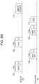
- FIG 8B illustrates another example the digital BF procedure according to Embodiment 1.
- digital BF is applied to the initiator link.
- initiator 102 transmits CT 702a and grant frame 702 to responder 104.
- CT 702a includes information indicating the antenna configuration used for the initiator link in the digital BF procedure.
- CT 704a includes information indicating the antenna configuration used for the responder link in the digital BF procedure.
- initiator 102 transmits CT 706a and RTS frame 706 to responder 104 to access a channel, and makes a notification about the start of the digital BF procedure for the initiator link.
- CT 706a includes information indicating the antenna configuration used for the initiator link in the digital BF procedure.
- responder 104 transmits CT 708a and DMG CTS frame 708 to respond to initiator 102.
- CT 708a includes information indicating the antenna configuration used for the responder link in the digital BF procedure.
- responder 104 configures array antennas for the responder link on the basis of the antenna configuration information in grant ack frame 704.
- responder 104 transmits EDMG BRP-TX packet 712 (the second BRP packet), which will be described below with reference to FIG 6 , thereby sounding a channel for the responder link (transmits a signal for channel measurement).
- EDMG BRP-TX packet 712 is transmitted with the antenna configuration for the responder link based on the result of the SU-MIMO BF training illustrated in FIG 2 or FIG 7 .
- initiator 102 transmits MIMO BF feedback frame 714 (the second MIMO BF feedback frame) including the SNR, MIMO channel measurement, or digital precoding matrix information for the responder link, to respond to responder 104.
- MIMO BF feedback frame 714 the second MIMO BF feedback frame
- BRP frame 712 is used to perform measurement of the responder link.
- measurement of the responder link is omitted in the SU-MIMO BF training illustrated in FIG 7 and measurement of the initiator link is omitted in FIG 8A or FIG 8B , the SNRs of both the initiator link and the responder link can be measured.
- responder 104 obtains feedback of the SNR for the responder link by using hybrid BF, and determines an appropriate modulation and coding scheme (MCS) on the basis of the SNR.
- MCS modulation and coding scheme
- the non-reciprocal/reciprocal SU-MIMO phase field described above with reference to FIG 5 may be included in CT 702a, 704a, 706a, or 708a described above with reference to FIG 8A and FIG 8B in addition to or instead of MIMO setup control element 400.
- responder 104 or initiator 102 designates reciprocal in CT 702a
- initiator 102 or responder 104 omits transmission of a BRP frame.
- the execution time of the digital BF procedure illustrated in FIG 8A or FIG 8B can be shortened and the power consumption can be reduced.
- responder 104 may transmit a DMG CTS to Self frame instead of DMG CTS 708.
- the DMG CTS to Self frame is a frame for notifying another STA that responder 104 will perform transmission after the DMG CTS to Self frame by setting responder 104 as both the source and destination addresses.
- the operation of transmitting a DMG CTS to Self frame as a response to RTS frame 706 is not specified in an existing standard, such as the 11ad standard, but the frame exchange order conforms to the existing standard.
- responder 104 Initiator 102 notifies responder 104 by setting a value indicating reciprocal in the non-reciprocal/reciprocal SU-MIMO phase field, thereby being capable of assuming that responder 104 transmits frames in an order different from that according to the 11ad standard.
- responder 104 is capable of performing DMG CTS to Self that is not defined in the 11ad standard in response to RTS frame 706, without increasing the complexity of control.
- responder 104 is capable of transmitting BRP 712 without increasing the complexity of control after transmitting DMG CTS 708.
- FIG 9 illustrates access to an SU-MIMO channel after the SU-MIMO BF training according to Embodiment 1 ( FIG 7 ) or after the SU-MIMO BF training illustrated in FIG 2 .
- Initiator 102 and responder 104 perform the SU-MIMO BF training illustrated in FIG 2 or FIG 7 and then accesses the SU-MIMO channel by using a recommended TX sector combination determined through the training.
- initiator 102 transmits CT 402a and grant frame 402 to responder 104.
- CT 402a includes information indicating that SU-MIMO transmission is to be used and information indicating a recommended TX sector combination to be used in SU-MIMO data transmission or a digital BF procedure for the initiator link.
- CT 404a includes information indicating that MIMO RX can be prepared by a target time, information indicating which of the initiator and the responder was the transmission source of CT 404a during the SU-MIMO BF training, and information indicating a recommended TX sector combination to be used in SU-MIMO data transmission or a digital BF procedure for the responder link. Note that, in the SU-MIMO BF training illustrated in FIG 2 or FIG 7 and the SU-MIMO channel access illustrated in FIG 9 , the initiator and the responder may change places.
- CT 404a includes an SU-MIMO transmission configuration type field.
- the SU-MIMO transmission configuration type field is a field indicating that a recommended TX sector combination can be obtained from the SU-MIMO BF training and feedback for the responder link or the initiator link.
- the SU-MIMO transmission configuration type field includes information indicating that a recommended TX sector combination can be obtained from the SU-MIMO BF training and feedback for the initiator link.
- initiator 102 may operate under the assumption that a recommended TX sector combination can be obtained from the SU-MIMO BF training and feedback for the initiator link without referring to the SU-MIMO transmission configuration type field.
- initiator 102 uses, as a recommended RX sector combination for the responder link, a recommended TX sector combination of initiator 102 indicated by grant frame 402.
- responder 104 sets, by using antenna pattern reciprocity, a recommended TX sector combination to be used by responder 104 as a recommended RX sector combination of responder 104 corresponding to the recommended TX sector combination of initiator 102 indicated by grant frame 402.
- CT 406a includes, like CT 402a, information indicating that SU-MIMO transmission is to be used and information indicating a recommended TX sector combination to be used in SU-MIMO data transmission or a digital BF procedure for the initiator link.
- CT 408a includes information indicating that MIMO RX is prepared, information indicating that SU-MIMO transmission is to be used in a reverse direction, and information indicating a recommended TX sector combination to be used in SU-MIMO data transmission or a digital BF procedure for the responder link.
- CT 408a includes, like CT 404a, an SU-MIMO transmission configuration type field.
- initiator 102 transmits data frame 410 to responder 104 by using the recommended TX sector combination indicated by CT 406a.
- responder 104 transmits ack frame 412 to respond to initiator 102.
- MU-MIMO BF training enables initiator 102 and one or plural responders 104 in a group to establish an antenna configuration that enables initiator 102 to transmit EDMG MU PPDU to the responders in the group such that mutual interference between streams transmitted in a physical layer protocol data unit (PPDU) is minimized.
- MU-MIMO BF training includes a SISO phase and a MIMO phase that are consecutive.
- the SISO phase collects feedback about TX of one or plural appropriate initiators and RX antennas of a responder, and sectors between the initiators and each responder in a group.
- the collected information may be used to execute the subsequent MIMO phase.
- the MIMO phase includes a downlink MIMO phase or an uplink MIMO phase.
- An SU-MIMO operation and an MU-MIMO operation are each an independent operation, and a terminal compatible with both the operations may perform either of them first.
- FIG 10 illustrates a downlink MIMO phase of MU-MIMO BF training according to Embodiment 1.
- the downlink MIMO phase includes four subphases, an MU-MIMO BF setup subphase, an MU-MIMO BF training subphase, an MU-MIMO BF feedback subphase, and an MU-MIMO BF selection subphase.
- initiator 102 In the MU-MIMO BF setup subphase of the downlink MIMO phase, initiator 102 first determines the number M of responders 104 in a group for performing training, on the basis of designation by the EDMG group and the group user mask illustrated in FIG 5 in which the correspondence with a set of MAC addresses is predetermined. Subsequently, initiator 102 transmits one or plural MIMO BF setup frames 902 to M responders 104 in the group.
- the SU/MU field and the DL/UL MU-MIMO phase field of the MIMO setup control element in MIMO BF setup frame 902 are set to 0 and 1, respectively, to indicate that the downlink MIMO phase is applied to MU-MIMO BF training.
- initiator 102 is capable of selecting a subset of candidate TX sectors for each antenna to reduce the time required for MU-MIMO BF training.
- initiator 102 After transmitting MIMO BF setup frames 902, initiator 102 starts the MU-MIMO BF training subphase. In the MU-MIMO BF training subphase, initiator 102 transmits EDMG BRP-RX/TX packets 910 to responders 104.
- initiator 102 After transmitting last EDMG BRP-RX/TX packet 912, initiator 102 starts the MU-MIMO BF feedback subphase. In the MU-MIMO BF feedback subphase, initiator 102 sequentially transmits MIMO BF polling frames to poll the individual responders in the group and collect MU-MIMO BF feedback.
- Each responder 104 receives MIMO BF polling frame 920.
- Each responder 104 checks an address written on MIMO BF polling frame 920 and, in a case where a corresponding address is written, corresponding responder 104 transmits MIMO BF feedback frame 922 to initiator 102.
- the MIMO BF feedback frame indicates the SNR that has been obtained via channel measurement data acquired from the MU-MIMO BF training subphase and that corresponds to N tsc recommended TX sector combinations and N tsc recommended TX sector combinations.
- the MIMO BF feedback frame can include a channel measurement result corresponding to the N tsc recommended TX sector combinations.
- N tsc means N tsc(I) .
- N tsc(I) is referred to as N tsc for simplicity.
- initiator 102 polls each responder 104, and starts the MU-MIMO BF selection subphase after receiving a MIMO BF feedback frame from M-th responder 104, that is, last responder 104 in the group.
- initiator 102 transmits one or plural MIMO BF selection frames 930 to individual responders 104 in the group.
- Each MIMO BF selection frame includes information about an MU-MIMO transmission configuration.
- initiator 102 starts an uplink MIMO phase of MU-MIMO BF training.
- FIG 11 illustrates an uplink MIMO phase of MU-MIMO BF training according to Embodiment 1.
- the uplink MIMO phase includes three subphases, an MU-MIMO BF setup subphase, an MU-MIMO BF training subphase, and an MU-MIMO BF selection subphase.
- initiator 102 transmits one or plural MIMO BF setup frames 1002 to individual responders 104 in the group.
- both the SU/MU field and the DL/LTL MU-MIMO phase field of the MIMO setup control element in MIMO BF setup frame 1002 are set to 0 to indicate that the uplink MIMO phase is applied to MU-MIMO BF training.
- initiator 102 After transmitting MIMO BF setup frames 1002, initiator 102 starts the MU-MIMO BF training subphase.
- initiator 102 sequentially transmits MIMO BF polling frames 1010 to individual responders 104 in the group.
- Each MIMO BF polling frame 1010 includes information indicating the number of TRN subfields to be used for receive AWV training in EDMG BRP-RX/TX packet 1012 subsequently transmitted by corresponding responder 104.
- Each responder 104 receives MIMO BF polling frame 1010.
- Responder 104 corresponding to the address included in MIMO BF polling frame 1010 transmits one or plural EDMG BRP-RX/TX packets 1012 to initiator 102.
- initiator 102 starts the MU-MIMO BF selection subphase after receiving the last EDMG BRP-RX/TX packet from M-th responder 104 in the group, that is, last responder 104 in the group.
- initiator 102 transmits one or plural MIMO BF selection frames 1030 to individual responders 104 in the group.
- Each MIMO BF selection frame includes information about an MU-MIMO transmission configuration.
- FIG 12 illustrates flowchart 1100 for setting the information fields of MIMO setup control element 400 according to Embodiment 1.
- Flowchart 1100 starts from step 1102.
- initiator 102 determines whether SU-MIMO or MU-MIMO BF training is intended. In a case where SU-MIMO BF training is intended (Yes in step 1104), flowchart 1100 proceeds to step 1110. Otherwise (No in step 1104), flowchart 1100 proceeds to step 1120.
- step 1110 the SU/MU field of MIMO setup control element 400 is set to 1 to indicate that SU-MIMO BF training is intended.
- step 1120 the SU/MU field of MIMO setup control element 400 is set to 0 to indicate that SU-MIMO BF training is not intended.
- step 1112 initiator 102 evaluates whether both initiator 102 and responder 104 have antenna pattern reciprocity. In a case where both initiator 102 and responder 104 have antenna pattern reciprocity (Yes in step 1112), flowchart 1100 proceeds to step 1114. Otherwise (No in step 1112), flowchart 1100 proceeds to step 1116.
- step 1116 the non-reciprocal/reciprocal SU-MIMO phase field of MIMO setup control element 400 is set to 1 to indicate that the non-reciprocal MIMO phase (see FIG 2 ) is applied to SU-MIMO BF training. Subsequently, flowchart 1100 ends in step 1130.
- step 1114 initiator 102 determines whether the reciprocal MIMO phase is intended to be applied to SU-MIMO BF training.
- the non-reciprocal/reciprocal SU-MIMO phase field of MIMO setup control element 400 is set to 0 to indicate that the reciprocal MIMO phase (see FIG 7 ) is applied to SU-MIMO BF training in step 1118, and subsequently flowchart 1100 ends in step 1130.
- flowchart 1100 proceeds to step 1116.
- step 1120 the SU/MU field of MIMO setup control element 400 is set to 0.
- step 1122 initiator 102 evaluates whether initiator 102 has antenna pattern reciprocity. In a case where initiator 102 has antenna pattern reciprocity (Yes in step 1122), flowchart 1100 proceeds to step 1124. Otherwise (No in step 1122), flowchart 1100 proceeds to step 1126, where the DL/LTL MU-MIMO phase field of MIMO setup control element 400 is set to 1 to indicate that the downlink MIMO phase (see FIG 10 ) is applied to MU-MIMO BF training. Subsequently, flowchart 1100 ends in step 1130.
- step 1124 initiator 102 determines whether the uplink MIMO phase is intended to be applied to MU-MIMO BF training. In a case where the uplink MIMO phase is intended to be applied to MU-MIMO BF training (Yes in step 1124), flowchart 1100 proceeds to step 1128. Otherwise (No in step 1124), flowchart 1100 proceeds to step 1126.
- step 1128 the DL/LTL MU-MIMO phase field of MIMO setup control element 400 is set to 0 to indicate that the uplink MIMO phase (see FIG 11 ) is applied to MU-MIMO BF training, and subsequently flowchart 1100 ends in step 1130. Otherwise (No in step 1124), flowchart 1100 proceeds to step 1126.
- FIG 13 illustrates flowchart 1200 for interpreting the information fields of MIMO setup control element 400 according to Embodiment 1.
- Flowchart 1200 starts from step 1202.
- responder 104 that has received MIMO setup control element 400 checks whether the SU/MU field is set to 1.
- flowchart 1200 proceeds to step 1210.
- flowchart 1200 proceeds to step 1220.
- responder 104 checks whether the non-reciprocal/reciprocal SU-MIMO phase field of received MIMO setup control element 400 is set to 0. In a case where the non-reciprocal/reciprocal SU-MIMO phase field is set to 0 (Yes in step 1210), flowchart 1200 proceeds to step 1214. In a case where the non-reciprocal/reciprocal SU-MIMO phase field is set to 1 (No in step 1210), flowchart 1200 proceeds to step 1212.
- responder 104 determines that the reciprocal MIMO phase is applied to SU-MIMO BF training, and flowchart 1200 ends in step 1230.
- responder 104 determines that the non-reciprocal MIMO phase is applied to SU-MIMO BF training, and flowchart 1200 ends in step 1230.
- step 1220 responder 104 checks whether the DL/UL MU-MIMO phase field of received MIMO setup control element 400 is set to 0. In a case where the DL/UL MU-MIMO phase field is set to 0 (Yes in step 1220), flowchart 1200 proceeds to step 1224. In a case where the DL/UL MU-MIMO phase field is set to 1 (No in step 1220), flowchart 1200 proceeds to step 1222.
- responder 104 determines that the uplink MIMO phase is applied to MU-MIMO BF training, and flowchart 1200 ends in step 1230.
- responder 104 determines that the downlink MIMO phase is applied to MU-MIMO BF training, and flowchart 1200 ends in step 1230.
- the R-SMBT subphase is omitted and the SU-MIMO BF feedback subphase is simplified. Accordingly, the time required for SU-MIMO BF training can be reduced compared with the non-reciprocal MIMO phase illustrated in FIG 2 .
- initiator 102 may determine an appropriate transmission parameter, for example, a MCS, to be used for communication with responder 104 that has transmitted MIMO BF feedback 922 illustrated in FIG 10 , on the basis of MIMO channel quality information included in MIMO BF feedback 922, for example, the SNR.
- initiator 102 may determine an appropriate transmission parameter, for example, a MCS, to be used for communication with responder 104 that has transmitted BRP frame 1012 illustrated in FIG 11 , in accordance with the reception quality of BRP frame 1012.
- initiator 102 is capable of determining an appropriate transmission parameter, for example, a MCS, to be used for communication with responder 104 after the digital BF procedure has been executed.
- initiator 102 may omit notifying responder 104 of information about receive sectors, and thus the time required for SU-MIMO BF training can be reduced.
- the MU-MIMO BF feedback subphase is omitted in the uplink MIMO phase illustrated in FIG 11 , compared with the downlink MIMO phase illustrated in FIG 10 .
- the time required for MU-MIMO BF training can be reduced.
- responder 104 determines an appropriate MCS to be used by responder 104 on the basis of MIMO BF feedback frame 714 transmitted by responder 104 in response to EDMG BRP-TX packet 712 transmitted by initiator 102.
- an opportunity to transmit feedback of the SNR for the responder link is acquired so that responder 104 is capable of determining an appropriate MCS on the basis of the SNR even in a case where the digital BF procedure cannot be used.
- FIG 14 illustrates a reciprocal MIMO phase of SU-MIMO BF training according to Modification Example 1.
- TRN field 624 is added to MIMO BF feedback frame 622 that is transmitted by responder 104 to transmit feedback of the SNR, as illustrated in FIG 14 .
- TRN field 624 is determined on the basis of recommended TX/RX sector combinations for the initiator link, and is transmitted by responder 104 by using recommended RX/TX sector combinations for the responder link.
- one or plural TRN units that are at the head of TRN field 624, that are added to MIMO BF feedback frame 622, and that cannot be processed by initiator 102 may be used by initiator 102 to switch the antenna configuration on the basis of the recommended RX/TX sector combinations for the responder link.
- initiator 102 transmits MIMO BF feedback frame 626 (a third MIMO BF feedback frame) including feedback of the SNR for the responder link.
- MIMO BF setup frame 602 MIMO BF setup frame 604, and EDMG BRP-RX/TX packets 610 illustrated in FIG 14 are similar to those illustrated in FIG 7 , and the description thereof is omitted.
- responder 104 is capable of determining an appropriate MCS to be used by responder 104 on the basis of feedback of the SNR for the responder link included in MIMO BF feedback frame 626.
- appropriate MCSs to be used by initiator 102 and responder 104 are determined through the SU-MIMO BF training illustrated in FIG 7 and the digital BF procedure illustrated in FIG 8A or FIG 8B .
- appropriate MCSs to be used by initiator 102 and responder 104 can be determined through the SU-MIMO BF training illustrated in FIG 14 .
- Initiator 102 may measure digital BF instead of measuring the SNR of the responder link, by using TRN field 624 illustrated in FIG 14 .
- responder 104 determines an appropriate MCS to be used by responder 104 on the basis of feedback of the SNR for the responder link transmitted by initiator 102.
- responder 104 determines an appropriate MCS to be used by responder 104 on the basis of information indicating a transmission power transmitted by initiator 102.
- FIG 15 illustrates a reciprocal MIMO phase of SU-MIMO BF training according to Modification Example 2.
- MIMO BF setup frame 602 transmitted by initiator 102 includes transmission EIRP field 602a indicating a transmission equivalent isotropic radiated power (EIRP) of initiator 102.
- Field 602a indicating the transmission EIRP may be inserted after, for example, the non-reciprocal/reciprocal SU-MIMO phase field of MIMO setup control element 400 illustrated in FIG 5 .
- responder 104 is capable of calculating a value RSSI I of RSSI of initiator 102 by using the following equation.
- RSSI I P R , TX ⁇ P I , TX + RSSI R
- P I, TX represents the value of the transmission EIRP of responder 104
- RSSI R represents the value of RSSI of responder 104.
- the values of P I, TX and RSSI R are known to responder 104.
- responder 104 is capable of determining an appropriate MCS to be used by responder 104 on the basis of the calculated value of RSSIi.
- MIMO BF setup frame 604, EDMG BRP-RX/TX packets 610, and MIMO BF feedback frame 622 illustrated in FIG 15 are similar to those illustrated in FIG 7 , and the description thereof is omitted.
- responder 104 is capable of determining an appropriate MCS to be used by responder 104 on the basis of the transmission EIRP of initiator 102.
- appropriate MCSs to be used by initiator 102 and responder 104 are determined through the SU-MIMO BF training illustrated in FIG 7 and the digital BF procedure illustrated in FIG 8A or FIG 8B .
- appropriate MCSs to be used by initiator 102 and responder 104 can be determined through the SU-MIMO BF training illustrated in FIG 15 .
- Modification Example 3 a case is considered in which both initiator 102 and responder 104 have antenna pattern reciprocity.
- transmission and reception of frames or packets corresponding to MIMO BF setup frame 204, I-SMBT, and MIMO BF feedback 234 among the frames illustrated in FIG 2 transmitted and received in the non-reciprocal MIMO phase are omitted.
- FIG 16 illustrates a reciprocal MIMO phase of SU-MIMO BF training according to Modification Example 3.
- the reciprocal MIMO phase of Modification Example 3 is formed of three subphases, an SU-MIMO BF setup subphase, an R-SMBT subphase, and an SU-MIMO BF feedback subphase.
- transmission and reception of frames or packets corresponding to MIMO BF setup frame 204, I-SMBT for the responder link, and MIMO BF feedback 234 for I-SMBT among the frames illustrated in FIG 2 transmitted and received in the non-reciprocal MIMO phase can be omitted.
- initiator 102 transmits MIMO BF setup frame 652 to responder 104.
- the values of the SU/MU field and the non-reciprocal/reciprocal SU-MIMO phase field of the MIMO setup control element in MIMO BF setup frame 652 are set to 1 and 0, respectively, to indicate that the reciprocal MIMO phase is applied to SU-MIMO BF training.
- the value of the link type field is set to 0 to indicate that the configuration information included in MIMO BF setup frame 652 is about the responder link.
- responder 104 starts the R-SMBT subphase.
- responder 104 transmits EDMG BRP-RX/TX packets 660 (a third BRP packet) to initiator 102.
- the number of TRN subfields of each EDMG BRP-RX/TX packet 660 is configured in accordance with the TRN configuration information in MIMO BF setup frame 652 received from initiator 102 in the SU-MIMO BF setup subphase.
- MIMO BF feedback frame 672 includes information indicating a recommended TX sector combination for the responder link determined on the basis of channel measurement data acquired from the R-SMBT subphase, and information indicating the SNR corresponding to the recommended TX sector combination.
- MIMO BF feedback frame 672 may include information indicating a channel measurement result corresponding to the recommended TX sector combination.
- initiator 102 determines a recommended TX sector combination to be used by initiator 102 for the initiator link.
- the recommended TX sector combination to be used by initiator 102 for the initiator link may be the same as the recommended RX sector combination to be used by initiator 102 for the responder link.
- responder 104 determines a recommended RX sector combination to be used by responder 104 for the initiator link.
- the recommended RX sector combination to be used by responder 104 for the initiator link may be the same as the recommended TX sector combination to be used by responder 104 for the responder link.
- appropriate MCSs to be used by initiator 102 and responder 104 are determined through the SU-MIMO BF training illustrated in FIG 7 and the digital BF procedure illustrated in FIG 8A or FIG 8B .
- appropriate MCSs to be used by initiator 102 and responder 104 can be determined through the SU-MIMO BF training illustrated in FIG 16 .
- Embodiment 1 two MIMO BF setup frames 602 and 604 are transmitted and received in a two-way manner in the SU-MIMO BF setup phase as illustrated in FIG 7 .
- one MIMO BF setup frame 652 is transmitted and received in a one-way manner in the SU-MIMO BF setup phase as illustrated in FIG 16 .
- the execution time can be shortened compared with the SU-MIMO BF setup phase in Embodiment 1.
- FIG 17 illustrates an example of a digital BF procedure according to Modification Example 3.
- digital BF is applied to the responder link.
- digital BF is applied to the initiator link.
- the SU-MIMO BF training (analog BF procedure) illustrated in FIG 7 is performed and then the digital BF procedure illustrated in FIG 8A or FIG 8B is performed.
- the analog BF procedure illustrated in FIG 16 is performed and then the digital BF procedure illustrated in FIG 17 is performed.
- initiator 102 transmits CT 702a and grant frame 702 to responder 104.
- CT 702a indicates the antenna configuration used for the initiator link in the digital BF procedure.
- responder 104 transmits CT 704a and grant ack frame 704 to respond to initiator 102.
- CT 704a indicates the antenna configuration used for the responder link in the digital BF procedure.
- initiator 102 transmits CT 706a and RTS frame 706 to responder 104 to access a channel, and makes a notification about the start of the digital BF procedure for the responder link.
- CT 706a indicates the antenna configuration used for the initiator link in the digital BF procedure.
- responder 104 transmits CT 708a and DMG CTS frame 708 to respond to initiator 102.
- CT 708a includes information indicating the antenna configuration used for the responder link in the digital BF procedure.
- initiator 102 configures array antennas for the initiator link on the basis of the antenna configuration information in grant frame 702.
- initiator 102 transmits EDMG BRP-TX packet 722 (a fourth BRP packet) illustrated in FIG 17 , thereby sounding a channel for the initiator link.
- EDMG BRP-TX packet 722 is transmitted with the antenna configuration for the initiator link based on the result of the SU-MIMO BF training illustrated in FIG 16 .
- responder 104 transmits MIMO BF feedback frame 724 (a fourth MIMO BF feedback frame) including the SNR, MIMO channel measurement, or digital precoding matrix information for the initiator link, to respond to initiator 102.
- MIMO BF feedback frame 724 (a fourth MIMO BF feedback frame) including the SNR, MIMO channel measurement, or digital precoding matrix information for the initiator link, to respond to initiator 102.
- BRP frame 612 is transmitted in the initiator link in the analog BF procedure, and BRP frame 712 is transmitted in the responder link in the digital BF procedure.
- BRP frame 662 is transmitted in the responder link in the analog BF procedure, and BRP frame 722 is transmitted in the initiator link in the digital BF procedure.
- BRP frames are transmitted in directions reverse to each other in the analog BF procedure and the digital BF procedure. Accordingly, even in a case where I-SMBT or R-SMBT is omitted, the SNRs of the respective links can be measured.
- initiator 102 obtains feedback of the SNR for the initiator link by using hybrid BF and determines an appropriate MCS on the basis of the SNR.
- initiator 102 is capable of determining an appropriate transmission parameter for the initiator link, for example, a MCS, after the digital BF procedure has been executed.
- responder 104 may omit notifying initiator 102 of information about receive sectors, and thus the time required for SU-MIMO BF training can be reduced.
- Modification Example 1 and Modification Example 3 may be combined to produce Modification Example 4.
- a TRN field is added to MIMO BF feedback frame 672 illustrated in FIG 16 , and MIMO BF feedback frame 672 and the TRN field are transmitted by initiator 102 by using recommended RX/TX sector combinations for the initiator link.
- the recommended RX/TX sector combinations for the initiator link are determined on the basis of recommended TX/RX sector combinations for the responder link. (See FIG 14 . Note that, in FIG 14 , responder 104 transmits TRN field 624.)
- responder 104 transmits a MIMO BF feedback frame including feedback of the SNR for the initiator link. (See FIG 14 . Note that, in FIG 14 , initiator 102 transmits MIMO BF feedback frame 626.)
- initiator 102 is capable of determining an appropriate MCS to be used by initiator 102 on the basis of the SNR of the initiator link.
- the downlink MIMO phase in MU-MIMO BF (see FIG 10 ) is referred to as a non-reciprocal MIMO phase.
- the uplink MIMO phase (see FIG 11 ) is referred to as a reciprocal MIMO phase because the uplink MIMO phase uses the antenna pattern reciprocity of initiator 102.
- FIG 18 illustrates an example of a format of MIMO setup control element 1300 according to Embodiment 2.
- MIMO setup control element 1300 includes an SU/MU field, a non-reciprocal/reciprocal MIMO phase field, and an initiator field.
- the SU/MU field indicates whether SU-MIMO or MU-MIMO BF is applied.
- the non-reciprocal/reciprocal MIMO phase field indicates which of a non-reciprocal MIMO phase and a reciprocal MIMO phase is applied to SU-MIMO BF training or MU-MIMO BF training.
- the initiator field indicates which of initiator 102 and responder 104 is the transmission source of MIMO setup control element 1300.
- Initiator 102 may transmit MIMO setup control element 1300 by including it in MIMO BF setup frame 602, 902, 1002, or 652.
- Responder 104 may transmit MIMO setup control element 1300 by including it in MIMO BF setup frame 604.
- the initiator field is used, instead of the link type field in Embodiment 1, in the MIMO setup control element.
- the link type field in FIG 5 indicates whether configuration information is information about the initiator link or information about the responder link.
- MIMO setup control element 1300 includes information about both the initiator link and the responder link, information about the initiator link, and information about the responder link. This will be described.
- the information about both the initiator link and the responder link includes, for example, information on the SU/MU field, an EDMG group ID field, and a group user mask field.
- the SU/MU field indicates which of SU-MIMO BF and MU-MIMO BF is to be executed, and is thus information about both the initiator link and the responder link.
- the IDs of communication devices that participate in MU-MIMO BF are determined by combining the EDMG group ID field and the group user mask field.
- the information about the initiator link includes, for example, information on a MIMO FBCK-REQ field and a transmission power field.
- the MIMO FBCK-REQ field indicates channel measurement feedback requested for the initiator link.
- the transmission power field indicates the transmission power of the initiator link.
- each field indicates information about the responder link.
- the information about the responder link includes, for example, information on an L-TX-RX field and a requested EDMG TRN unit M field.
- the L-TX-RX field and the requested EDMG TRN unit M field indicate the number of TRN subfields requested for receive AWV training for the responder link.
- each field indicates information about the initiator link.
- Initiator 102 includes, in MIMO setup control element 1300, an initiator field indicating which of initiator 102 and responder 104 is a transmitter of MIMO setup control element 1300.
- Responder 104 that has received MIMO setup control element 1300 is capable of determining, by using the value indicated by the initiator field, which of the information about both the initiator link and the responder link, the information about the initiator link, and the information about the responder link is the configuration information (information in each field) of MIMO setup control element 1300.
- the initiator field is included in MIMO setup control element 1300 also in a case where responder 104 transmits MIMO setup control element 1300.
- responder 104 is capable of discriminating the configuration information (information in each field) of MIMO setup control element 1300 by using the value indicated by the initiator field.
- the SU/MU field and the non-reciprocal/reciprocal MIMO phase field in the format of MIMO setup control element 1300 in FIG 18 indicate which of the non-reciprocal MIMO phase of SU-MIMO BF training illustrated in FIG 2 , the reciprocal MIMO phase of SU-MIMO BF training illustrated in FIG 7 , the non-reciprocal MIMO phase of MU-MIMO BF training illustrated in FIG 10 , and the reciprocal MIMO phase of MU-MIMO BF training illustrated in FIG 11 is to be used.
- both the SU/MU field and the non-reciprocal/reciprocal MIMO phase field of MIMO setup control element 1300 in MIMO BF setup frame 202 or MIMO BF setup frame 204 are set to 0 to indicate that the non-reciprocal MIMO phase is applied to SU-MIMO BF training.
- the initiator field of MIMO setup control element 1300 in MIMO BF setup frame 202 is set to 1 to indicate that the transmission source of MIMO BF setup frame 202 is initiator 102.
- the initiator field of MIMO setup control element 1300 in MIMO BF setup frame 204 is set to 0 to indicate that the transmission source of MIMO BF setup frame 204 is responder 104.
- both the SU/MU field and the non-reciprocal/reciprocal MIMO phase field of MIMO setup control element 1300 in MIMO BF setup frame 602 or MIMO BF setup frame 604 are set to 0 and 1, respectively, to indicate that the reciprocal MIMO phase is applied to SU-MIMO BF training.
- the initiator field of MIMO setup control element 1300 in MIMO BF setup frame 602 is set to 1 to indicate that the transmission source of MIMO BF setup frame 602 is initiator 102.
- the initiator field of MIMO setup control element 1300 in MIMO BF setup frame 604 is set to 0 to indicate that the transmission source of MIMO BF setup frame 604 is responder 104.
- both the SU/MU field and the non-reciprocal/reciprocal MIMO phase field of MIMO setup control element 1300 in MIMO BF setup frame 902 are set to 1 and 0, respectively, to indicate that the non-reciprocal MIMO phase is applied to MU-MIMO BF training.
- the initiator field of MIMO setup control element 1300 in MIMO BF setup frame 902 is set to 1 to indicate that the transmission source of MIMO BF setup frame 902 is initiator 102.
- both the SU/MU field and the non-reciprocal/reciprocal MIMO phase field of MIMO setup control element 1300 in MIMO BF setup frame 1002 are set to 1 to indicate that the reciprocal MIMO phase is applied to MU-MIMO BF training.
- the initiator field of MIMO setup control element 1300 in MIMO BF setup frame 1002 is set to 1 to indicate that the transmission source of MIMO BF setup frame 1002 is initiator 102.
- FIG 19 illustrates flowchart 1400 for setting the information fields of MIMO setup control element 1300 according to Embodiment 2.
- Flowchart 1400 starts from step 1402.
- initiator 102 determines whether SU-MIMO or MU-MIMO BF training is intended.
- flowchart 1400 proceeds to step 1410. Otherwise (No in step 1404), flowchart 1400 proceeds to step 1420.
- step 1410 the SU/MU field of MIMO setup control element 1300 is set to 0 to indicate that SU-MIMO BF training is intended.
- step 1412 initiator 102 evaluates whether both initiator 102 and responder 104 have antenna pattern reciprocity. In a case where both initiator 102 and responder 104 have antenna pattern reciprocity (Yes in step 1412), flowchart 1400 proceeds to step 1414. Otherwise (No in step 1412), flowchart 1400 proceeds to step 1416.
- step 1416 the non-reciprocal/reciprocal MIMO phase field of MIMO setup control element 1300 is set to 0 to indicate that the non-reciprocal MIMO phase (see FIG 2 ) is applied to SU-MIMO BF training. Subsequently, flowchart 1400 ends in step 1430.
- step 1414 initiator 102 determines whether the reciprocal MIMO phase is intended to be applied to SU-MIMO BF training. In a case where the reciprocal MIMO phase is intended to be applied to SU-MIMO BF training (Yes in step 1414), flowchart 1400 proceeds to step 1418. Otherwise (No in step 1414), flowchart 1400 proceeds to step 1416.
- step 1418 the non-reciprocal/reciprocal MIMO phase field of MIMO setup control element 1300 is set to 1 to indicate that the reciprocal MIMO phase (see FIG 7 ) is applied to SU-MIMO BF training, and subsequently flowchart 1400 ends in step 1430.
- step 1420 the SU/MU field of MIMO setup control element 1300 is set to 1 to indicate that MU-MIMO BF training is intended.
- step 1422 initiator 102 evaluates whether initiator 102 has antenna pattern reciprocity. In a case where initiator 102 has antenna pattern reciprocity (Yes in step 1422), flowchart 1400 proceeds to step 1424. Otherwise (No in step 1422), flowchart 1400 proceeds to step 1426.
- step 1426 the non-reciprocal/reciprocal MIMO phase field of MIMO setup control element 1300 is set to 0 to indicate that the non-reciprocal MIMO phase (see FIG 10 ) is applied to MU-MIMO BF training. Subsequently, flowchart 1400 ends in step 1430.
- step 1424 initiator 102 determines whether the reciprocal MIMO phase is intended to be applied to MU-MIMO BF training. In a case where the reciprocal MIMO phase is intended to be applied to MU-MIMO BF training (Yes in step 1424), flowchart 1400 proceeds to step 1428. Otherwise (No in step 1424), flowchart 1400 proceeds to step 1426.
- step 1428 the non-reciprocal/reciprocal MIMO phase field of MIMO setup control element 1300 is set to 1 to indicate that the reciprocal MIMO phase (see FIG 11 ) is applied to MU-MIMO BF training, and subsequently flowchart 1400 ends in step 1430.
- FIG 20 illustrates flowchart 1500 for interpreting the information fields of MIMO setup control element 1300 according to Embodiment 2.
- Flowchart 1500 starts from step 1502.
- responder 104 that has received MIMO setup control element 1300 checks whether the SU/MU field is set to 0. In a case where the SU/MU field is set to 0 (Yes in step 1504), flowchart 1500 proceeds to step 1510. Otherwise (No in step 1504), flowchart 1500 proceeds to step 1520.
- step 1510 responder 104 checks whether the non-reciprocal/reciprocal MIMO phase field of received MIMO setup control element 1300 is set to 1. In a case where the non-reciprocal/reciprocal MIMO phase field is set to 1 (Yes in step 1510), flowchart 1500 proceeds to step 1514. Otherwise (No in step 1510), flowchart 1500 proceeds to step 1512.
- responder 104 determines that the reciprocal MIMO phase is applied to SU-MIMO BF training, and flowchart 1500 ends in step 1530.
- responder 104 determines that non-reciprocal MIMO phase is applied to SU-MIMO BF training, and flowchart 1500 ends in step 1530.
- step 1520 responder 104 checks whether the non-reciprocal/reciprocal MIMO phase field of received MIMO setup control element 1300 is set to 1. In a case where the non-reciprocal/reciprocal MIMO phase field is set to 1 (Yes in step 1520), flowchart 1500 proceeds to step 1524. Otherwise (No in step 1520), flowchart 1500 proceeds to step 1522.
- step 1524 responder 104 determines that the reciprocal MIMO phase is applied to MU-MIMO BF training, and flowchart 1500 ends in step 1530.
- step 1522 responder 104 determines that the non-reciprocal MIMO phase is applied to MU-MIMO BF training, and flowchart 1500 ends in step 1530.
- Embodiment 2 one signal transmission bit in a MIMO setup control element can be saved compared with Embodiment 1.
- the present disclosure can be realized by software, hardware, or software in cooperation with hardware.
- Each functional block used in the description of each embodiment described above can be partly or entirely realized by an LSI such as an integrated circuit, and each process described in the each embodiment may be controlled partly or entirely by the same LSI or a combination of LSIs.
- the LSI may be individually formed as chips, or one chip may be formed so as to include a part or all of the functional blocks.
- the LSI may include a data input and output coupled thereto.
- the LSI here may be referred to as an IC, a system LSI, a super LSI, or an ultra LSI depending on a difference in the degree of integration.
- the technique of implementing an integrated circuit is not limited to the LSI and may be realized by using a dedicated circuit, a general-purpose processor, or a special-purpose processor.
- a FPGA Field Programmable Gate Array
- a reconfigurable processor in which the connections and the settings of circuit cells disposed inside the LSI can be reconfigured may be used.
- the present disclosure can be realized as digital processing or analogue processing. If future integrated circuit technology replaces LSIs as a result of the advancement of semiconductor technology or other derivative technology, the functional blocks could be integrated using the future integrated circuit technology. Biotechnology can also be applied.
- a communication system (an initiator device and a responder device) can be used for communication between vehicles, communication between a road and a vehicle, communication between a vehicle and a store, communication between a train and a station platform, and communication between an aircraft and a boarding bridge (passenger step).
- An initiator device is a device that supports a single user (SU)-multiple input multiple output (MIMO) operation, including: a generation circuit that generates a first signal including a value indicating which of a reciprocal MIMO phase and a non-reciprocal MIMO phase is applied to SU-MIMO beamforming (BF) training; and a transmission circuit that transmits the first signal to a responder device.
- SU single user
- MIMO multiple input multiple output
- the first signal includes a value indicating that the reciprocal MIMO phase is applied to the SU-MIMO BF training.
- the first signal is a MIMO BF setup frame.
- the initiator device includes: a reception circuit; and a control circuit, in which, in a case where the reciprocal MIMO phase is applied to the SU-MIMO BF training, the transmission circuit transmits to the responder device a first beam refinement protocol (BRP) signal for training transmit sectors that are to be used for MIMO transmission by the initiator device, the reception circuit receives from the responder device a first MIMO BF feedback signal including feedback information for the first BRP signal, and the control circuit determines, on the basis of the feedback information for the first BRP signal, a transmit sector combination and a receive sector combination that are to be used for MIMO transmission by the initiator device.
- BRP beam refinement protocol
- the reception circuit receives from the responder device a second BRP signal for training a transmit sector combination that is to be used for MIMO transmission by the responder device, and the transmission circuit transmits to the responder device a second MIMO BF feedback signal including feedback information for the second BRP signal.
- the reception circuit receives from the responder device a training (TRN) signal for training a transmit sector combination that is to be used for MIMO transmission by the responder device, the TRN signal being added to the first MIMO BF feedback signal, and the transmission circuit transmits to the responder device a third MIMO BF feedback signal including feedback information for the TRN signal.
- TRN training
- the first signal includes information indicating a transmission power of the transmit sector combination.
- the reception circuit receives from the responder device a third BRP signal for training a transmit sector combination that is to be used for MIMO transmission by the responder device, the transmission circuit transmits to the responder device a third MIMO BF feedback signal including feedback information for the third BRP signal, and the control circuit determines, on the basis of the third BRP signal, a transmit sector combination and a receive sector combination that are to be used for MIMO transmission by the initiator device.
- the reception circuit receives from the responder device a fourth BRP signal with which the responder device sounds a channel for a responder link, and the transmission circuit transmits to the responder device a fourth MIMO BF feedback signal including feedback information for the fourth BRP signal.
- a responder device is a device that supports a single user (SU)-multiple input multiple output (MIMO) operation, including: a reception circuit that receives from an initiator device a first signal including a value indicating which of a reciprocal MIMO phase and a non-reciprocal MIMO phase is applied to SU-MIMO beamforming (BF) training; and a processing circuit that determines, on the basis of the value, which of the reciprocal MIMO phase and the non-reciprocal MIMO phase is applied to the SU-MIMO BF training.
- SU single user
- MIMO multiple input multiple output
- the first signal is a MIMO BF setup signal.
- the responder device includes: a transmission circuit; and a control circuit, in which, in a case where the processing circuit determines that the reciprocal MIMO phase is applied to the SU-MIMO BF training, the reception circuit receives from the initiator device a first beam refinement protocol (BRP) signal for training a transmit sector combination that is to be used for MIMO transmission by the initiator device, the transmission circuit transmits to the initiator device a first MIMO BF feedback signal including feedback information for the first BRP signal, and the control circuit determines, on the basis of the first BRP signal, a transmit sector combination and a receive sector combination that are to be used for MIMO transmission by the responder device.
- BRP beam refinement protocol
- the transmission circuit transmits to the initiator device a second BRP signal for training a transmit sector combination that is to be used for MIMO transmission by the responder device, the reception circuit receives from the initiator device a second MIMO BF feedback signal including feedback information for the second BRP signal, and the control circuit determines, on the basis of the feedback information for the second BRP signal, a modulation and coding scheme for MIMO transmission by the responder device.
- the transmission circuit transmits to the initiator device a training (TRN) signal for training a transmit sector combination that is to be used for MIMO transmission by the responder device, the TRN signal being added to the first MIMO BF feedback signal, the reception circuit receives from the responder device a third MIMO BF feedback signal including feedback information for the TRN signal, and the control circuit determines, on the basis of the feedback information for the TRN signal, a modulation and coding scheme for MIMO transmission by the responder device.
- TRN training
- the first signal includes information indicating a transmission power of the transmit sector combination
- the control circuit determines, on the basis of the information indicating the transmission power, a modulation and coding scheme for MIMO transmission by the responder device.
- the transmission circuit transmits to the initiator device a third BRP signal for training a transmit sector combination that is to be used for MIMO transmission by the responder device, the reception circuit receives from the responder device a third MIMO BF feedback signal including feedback information for the third BRP signal, and the control circuit determines, on the basis of the feedback information for the third BRP signal, a transmit sector combination and a receive sector combination that are to be used for MIMO transmission by the responder device.
- the transmission circuit transmits to the initiator device a fourth BRP signal with which the responder device sounds a channel for a responder link
- the reception circuit receives from the initiator device a fourth MIMO BF feedback signal including feedback information for the fourth BRP signal
- the control circuit determines, on the basis of the feedback information for the fourth BRP signal, a modulation and coding scheme for MIMO transmission by the responder device.
- a system includes: an initiator device and a responder device that support a single user (SU)-multiple input multiple output (MIMO) operation, in which the initiator device includes a generation circuit that generates a first signal including a value indicating which of a reciprocal MIMO phase and a non-reciprocal MIMO phase is applied to SU-MIMO beamforming (BF) training, and a transmission circuit that transmits the first signal to the responder device, and in which the responder device includes a reception circuit that receives the first signal from the initiator device, and a processing circuit that determines, on the basis of the value, which of the reciprocal MIMO phase and the non-reciprocal MIMO phase is applied to the SU-MIMO BF training.
- SU single user
- MIMO multiple input multiple output
- the present disclosure is useful for a multi-user wireless communication system.
- An initiator device that supports a single user (SU)-multiple input multiple output (MIMO) operation, comprising: a generation circuit that generates a first signal including a value indicating which of a reciprocal MIMO phase and a non-reciprocal MIMO phase is applied to SU-MIMO beamforming (BF) training; and a transmission circuit that transmits the first signal to a responder device.
- SU single user
- MIMO multiple input multiple output
- the first signal includes a value indicating that the reciprocal MIMO phase is applied to the SU-MIMO BF training.
- Clause 3 The initiator device according to clause 1, wherein the first signal is a MIMO BF setup frame.
- Clause 4 The initiator device according to clause 1, comprising: a reception circuit; and a control circuit, wherein in a case where the reciprocal MIMO phase is applied to the SU-MIMO BF training, the transmission circuit transmits to the responder device a first beam refinement protocol (BRP) signal for training transmit sectors that are to be used for MIMO transmission by the initiator device, the reception circuit receives from the responder device a first MIMO BF feedback signal including feedback information for the first BRP signal, and the control circuit determines, on the basis of the feedback information for the first BRP signal, a transmit sector combination and a receive sector combination that are to be used for MIMO transmission by the initiator device.
- BRP beam refinement protocol
- Clause 5 The initiator device according to clause 4, wherein in a digital BF procedure of a hybrid BF operation that is performed after the SU-MIMO BF training, the reception circuit receives from the responder device a second BRP signal for training a transmit sector combination that is to be used for MIMO transmission by the responder device, and the transmission circuit transmits to the responder device a second MIMO BF feedback signal including feedback information for the second BRP signal.
- Clause 6 The initiator device according to clause 4, wherein the reception circuit receives from the responder device a training (TRN) signal for training a transmit sector combination that is to be used for MIMO transmission by the responder device, the TRN signal being added to the first MIMO BF feedback signal, and the transmission circuit transmits to the responder device a third MIMO BF feedback signal including feedback information for the TRN signal.
- TRN training
- Clause 7 The initiator device according to clause 4, wherein the first signal includes information indicating a transmission power of the transmit sector combination.
- Clause 8 The initiator device according to clause 1, comprising: a reception circuit; and a control circuit, wherein in a case where the reciprocal MIMO phase is applied to the SU-MIMO BF training, the reception circuit receives from the responder device a third BRP signal for training a transmit sector combination that is to be used for MIMO transmission by the responder device, the transmission circuit transmits to the responder device a third MIMO BF feedback signal including feedback information for the third BRP signal, and the control circuit determines, on the basis of the third BRP signal, a transmit sector combination and a receive sector combination that are to be used for MIMO transmission by the initiator device.
- Clause 9 The initiator device according to clause 8, wherein in a digital BF procedure of a hybrid BF operation that is performed after the SU-MIMO BF training, the reception circuit receives from the responder device a fourth BRP signal with which the responder device sounds a channel for a responder link, and the transmission circuit transmits to the responder device a fourth MIMO BF feedback signal including feedback information for the fourth BRP signal.
- a responder device that supports a single user (SU)-multiple input multiple output (MIMO) operation, comprising: a reception circuit that receives from an initiator device a first signal including a value indicating which of a reciprocal MIMO phase and a non-reciprocal MIMO phase is applied to SU-MIMO beamforming (BF) training; and a processing circuit that determines, on the basis of the value, which of the reciprocal MIMO phase and the non-reciprocal MIMO phase is applied to the SU-MIMO BF training.
- SU single user
- MIMO multiple input multiple output
- Clause 11 The responder device according to clause 10, wherein the first signal is a MIMO BF setup signal.
- Clause 12 The responder device according to clause 10, comprising: a transmission circuit; and a control circuit, wherein in a case where the processing circuit determines that the reciprocal MIMO phase is applied to the SU-MIMO BF training, the reception circuit receives from the initiator device a first beam refinement protocol (BRP) signal for training a transmit sector combination that is to be used for MIMO transmission by the initiator device, the transmission circuit transmits to the initiator device a first MIMO BF feedback signal including feedback information for the first BRP signal, and the control circuit determines, on the basis of the first BRP signal, a transmit sector combination and a receive sector combination that are to be used for MIMO transmission by the responder device.
- BRP beam refinement protocol
- Clause 13 The responder device according to clause 12, wherein in a digital BF procedure of a hybrid BF operation that is performed after the SU-MIMO BF training, the transmission circuit transmits to the initiator device a second BRP signal for training a transmit sector combination that is to be used for MIMO transmission by the responder device, the reception circuit receives from the initiator device a second MIMO BF feedback signal including feedback information for the second BRP signal, and the control circuit determines, on the basis of the feedback information for the second BRP signal, a modulation and coding scheme for MIMO transmission by the responder device.
- Clause 14 The responder device according to clause 12, wherein the transmission circuit transmits to the initiator device a training (TRN) signal for training a transmit sector combination that is to be used for MIMO transmission by the responder device, the TRN signal being added to the first MIMO BF feedback signal, the reception circuit receives from the responder device a third MIMO BF feedback signal including feedback information for the TRN signal, and the control circuit determines, on the basis of the feedback information for the TRN signal, a modulation and coding scheme for MIMO transmission by the responder device.
- TRN training
- the transmission circuit transmits to the initiator device a training (TRN) signal for training a transmit sector combination that is to be used for MIMO transmission by the responder device, the TRN signal being added to the first MIMO BF feedback signal
- the reception circuit receives from the responder device a third MIMO BF feedback signal including feedback information for the TRN signal
- the control circuit determines, on the basis of the feedback information for the TRN signal, a modulation and coding
- Clause 15 The responder device according to clause 12, wherein the first signal includes information indicating a transmission power of the transmit sector combination, and the control circuit determines, on the basis of the information indicating the transmission power, a modulation and coding scheme for MIMO transmission by the responder device.
- Clause 16 The responder device according to clause 10, wherein in a case where the processing circuit determines that the reciprocal MIMO phase is applied to the SU-MIMO BF training, the transmission circuit transmits to the initiator device a third BRP signal for training a transmit sector combination that is to be used for MIMO transmission by the responder device, the reception circuit receives from the responder device a third MIMO BF feedback signal including feedback information for the third BRP signal, and the control circuit determines, on the basis of the feedback information for the third BRP signal, a transmit sector combination and a receive sector combination that are to be used for MIMO transmission by the responder device.
- Clause 17 The responder device according to clause 16, wherein in a digital BF procedure of a hybrid BF operation that is performed after the SU-MIMO BF training, the transmission circuit transmits to the initiator device a fourth BRP signal with which the responder device sounds a channel for a responder link, the reception circuit receives from the initiator device a fourth MIMO BF feedback signal including feedback information for the fourth BRP signal, and the control circuit determines, on the basis of the feedback information for the fourth BRP signal, a modulation and coding scheme for MIMO transmission by the responder device.
- a system comprising: an initiator device and a responder device that support a single user (SU)-multiple input multiple output (MIMO) operation, wherein the initiator device includes a generation circuit that generates a first signal including a value indicating which of a reciprocal MIMO phase and a non-reciprocal MIMO phase is applied to SU-MIMO beamforming (BF) training, and a transmission circuit that transmits the first signal to the responder device, and wherein the responder device includes a reception circuit that receives the first signal from the initiator device, and a processing circuit that determines, on the basis of the value, which of the reciprocal MIMO phase and the non-reciprocal MIMO phase is applied to the SU-MIMO BF training.
- SU single user
- MIMO multiple input multiple output
Landscapes
- Engineering & Computer Science (AREA)
- Computer Networks & Wireless Communication (AREA)
- Signal Processing (AREA)
- Radio Transmission System (AREA)
- Mobile Radio Communication Systems (AREA)
- Radar Systems Or Details Thereof (AREA)
Applications Claiming Priority (5)
| Application Number | Priority Date | Filing Date | Title |
|---|---|---|---|
| US201762575264P | 2017-10-20 | 2017-10-20 | |
| US201862628199P | 2018-02-08 | 2018-02-08 | |
| JP2018172815A JP7154078B2 (ja) | 2017-10-20 | 2018-09-14 | イニシエータ装置、通信方法、および集積回路 |
| PCT/JP2018/038686 WO2019078261A1 (fr) | 2017-10-20 | 2018-10-17 | Dispositif initiateur, dispositif répondeur et système |
| EP18868560.6A EP3700100B1 (fr) | 2017-10-20 | 2018-10-17 | Dispositif initiateur, dispositif répondeur et système |
Related Parent Applications (2)
| Application Number | Title | Priority Date | Filing Date |
|---|---|---|---|
| EP18868560.6A Division-Into EP3700100B1 (fr) | 2017-10-20 | 2018-10-17 | Dispositif initiateur, dispositif répondeur et système |
| EP18868560.6A Division EP3700100B1 (fr) | 2017-10-20 | 2018-10-17 | Dispositif initiateur, dispositif répondeur et système |
Publications (2)
| Publication Number | Publication Date |
|---|---|
| EP4258568A2 true EP4258568A2 (fr) | 2023-10-11 |
| EP4258568A3 EP4258568A3 (fr) | 2023-11-15 |
Family
ID=66628863
Family Applications (2)
| Application Number | Title | Priority Date | Filing Date |
|---|---|---|---|
| EP23188843.9A Withdrawn EP4258568A3 (fr) | 2017-10-20 | 2018-10-17 | Dispositif initiateur, dispositif répondeur et système |
| EP18868560.6A Active EP3700100B1 (fr) | 2017-10-20 | 2018-10-17 | Dispositif initiateur, dispositif répondeur et système |
Family Applications After (1)
| Application Number | Title | Priority Date | Filing Date |
|---|---|---|---|
| EP18868560.6A Active EP3700100B1 (fr) | 2017-10-20 | 2018-10-17 | Dispositif initiateur, dispositif répondeur et système |
Country Status (11)
| Country | Link |
|---|---|
| US (4) | US11223393B2 (fr) |
| EP (2) | EP4258568A3 (fr) |
| JP (2) | JP7154078B2 (fr) |
| KR (2) | KR102564091B1 (fr) |
| CN (3) | CN115189707B (fr) |
| BR (1) | BR112020007760A2 (fr) |
| CA (1) | CA3079382C (fr) |
| CO (1) | CO2020004763A2 (fr) |
| MX (1) | MX2020003363A (fr) |
| MY (1) | MY203880A (fr) |
| TW (1) | TWI794308B (fr) |
Families Citing this family (4)
| Publication number | Priority date | Publication date | Assignee | Title |
|---|---|---|---|---|
| ES2898074T3 (es) * | 2016-11-02 | 2022-03-03 | Panasonic Ip Corp America | Dispositivo de comunicación y procedimiento de comunicación |
| WO2019135557A1 (fr) * | 2018-01-03 | 2019-07-11 | 엘지전자 주식회사 | Procédé d'émission et de réception de signal dans un système lan sans fil, et appareil associé |
| EP3893406B1 (fr) * | 2018-12-06 | 2024-02-28 | LG Electronics Inc. | Appareil destiné à effectuer une formation de faisceau à l'aide de multiples antennes dans un système av sans fil |
| US12232098B2 (en) * | 2022-02-07 | 2025-02-18 | Qualcomm Incorporated | Proactive communication of hybrid beamforming parameters between devices |
Citations (1)
| Publication number | Priority date | Publication date | Assignee | Title |
|---|---|---|---|---|
| JP2018172815A (ja) | 2017-03-31 | 2018-11-08 | ユニチカトレーディング株式会社 | リング精紡交撚糸、該リング精紡交撚糸を含む織編物、及び該リング精紡交撚糸の製造方法 |
Family Cites Families (30)
| Publication number | Priority date | Publication date | Assignee | Title |
|---|---|---|---|---|
| US7676007B1 (en) | 2004-07-21 | 2010-03-09 | Jihoon Choi | System and method for interpolation based transmit beamforming for MIMO-OFDM with partial feedback |
| JP4356756B2 (ja) * | 2006-04-27 | 2009-11-04 | ソニー株式会社 | 無線通信システム、並びに無線通信装置及び無線通信方法 |
| JP4775288B2 (ja) * | 2006-04-27 | 2011-09-21 | ソニー株式会社 | 無線通信システム、無線通信装置及び無線通信方法 |
| US8787841B2 (en) * | 2006-06-27 | 2014-07-22 | Qualcomm Incorporated | Method and system for providing beamforming feedback in wireless communication systems |
| CN101753193B (zh) * | 2008-12-22 | 2013-08-14 | 电信科学技术研究院 | 一种区分多用户信道估计的方法及设备 |
| EP2234355B1 (fr) * | 2009-03-25 | 2012-10-31 | IHP GmbH-Innovations for High Performance Microelectronics / Leibniz-Institut für innovative Mikroelektronik | Transmission MIMO dans des systèmes WLAN IEEE802.11 |
| CN102771060B (zh) * | 2009-11-24 | 2016-05-18 | 韩国电子通信研究院 | 用于在基于多用户多输入多输出的无线通信系统中恢复传送失败的帧的方法 |
| US9401753B2 (en) * | 2009-12-23 | 2016-07-26 | Intel Corporation | Native medium access control support for beamforming |
| US8971178B1 (en) * | 2010-04-05 | 2015-03-03 | Marvell International Ltd. | Calibration correction for implicit beamformer using an explicit beamforming technique in a wireless MIMO communication system |
| CN102497644B (zh) * | 2011-12-22 | 2014-08-13 | 电子科技大学 | 一种低复杂度正交迭代波束成形的方法 |
| US9608789B2 (en) * | 2012-05-11 | 2017-03-28 | Interdigital Patent Holdings, Inc. | Method and apparatus for transmitting acknowledgements in response to received frames |
| US9225401B2 (en) * | 2012-05-22 | 2015-12-29 | Mediatek Singapore Pte. Ltd. | Method and apparatus of beam training for MIMO operation and multiple antenna beamforming operation |
| US9048894B2 (en) * | 2012-05-22 | 2015-06-02 | Mediatek Singapore Pte. Ltd. | Method and apparatus of beam training for MIMO operation |
| US9991940B2 (en) * | 2013-09-10 | 2018-06-05 | Qualcomm Incorporated | Multi-user multiple-input multiple-output (MU-MIMO) feedback protocol |
| WO2016027398A1 (fr) * | 2014-08-18 | 2016-02-25 | パナソニック株式会社 | Procédé d'apprentissage mimo et dispositif radio |
| US9722726B2 (en) * | 2015-03-28 | 2017-08-01 | Intel IP Corporation | Reciprocity detection and utilization techniques for beamforming training |
| US9893785B2 (en) | 2015-09-11 | 2018-02-13 | Intel IP Corporation | Enhanced beamforming training in a wireless local area networks |
| US9999046B2 (en) * | 2015-09-11 | 2018-06-12 | Intel Corporation | Sector level sweep for millimeter-wave multiple output communications |
| US10142005B2 (en) * | 2015-11-02 | 2018-11-27 | Lg Electronics Inc. | Beamforming training |
| US10312980B2 (en) * | 2015-11-06 | 2019-06-04 | Futurewei Technologies, Inc. | Method and apparatus for multiuser MIMO beamforming training |
| US9698885B1 (en) | 2015-12-31 | 2017-07-04 | Facebook, Inc. | Link acquistion in directional wireless systems |
| US20170223741A1 (en) * | 2016-02-03 | 2017-08-03 | Qualcomm Incorporated | Efficient clear channel assessment (cca) with request-to-send (rts) frame and clear-to-send (cts) frame |
| EP3427402A1 (fr) * | 2016-03-10 | 2019-01-16 | Interdigital Patent Holdings, Inc. | Apprentissage de faisceaux multirésolution dans des systèmes wlan à ondes millimétriques |
| KR102341978B1 (ko) | 2016-03-10 | 2021-12-24 | 인터디지탈 패튼 홀딩스, 인크 | 무선 근거리 통신망에서 빔포밍 트레이닝을 위한 시스템 및 방법 |
| EP3240201A1 (fr) * | 2016-04-27 | 2017-11-01 | MediaTek Inc. | Opération à entrées multiples, sorties multiples multiutilisateur (mu-mimo) et sélection d'utilisateur |
| US10855350B2 (en) * | 2016-05-12 | 2020-12-01 | Interdigital Patent Holdings, Inc. | Systems and methods for beamforming feedback in mm wave wireless local area networks |
| EP3455955A1 (fr) | 2016-05-12 | 2019-03-20 | Interdigital Patent Holdings, Inc. | Systèmes et procédés pour mimo hybride mono-utilisateur pour réseaux sans fil à ondes millimétriques |
| KR102371879B1 (ko) * | 2016-07-21 | 2022-03-08 | 인터디지탈 패튼 홀딩스, 인크 | Mmw wlan 시스템에서의 mimo 모드 적응 |
| WO2019022450A1 (fr) * | 2017-07-28 | 2019-01-31 | 엘지전자 주식회사 | Procédé permettant de réaliser un apprentissage de formation de faisceau mu-mimo dans un système lan sans fil, et procédé et dispositif permettant de prendre en charge un apprentissage de formation de faisceau mu-mimo |
| KR102208398B1 (ko) * | 2017-09-01 | 2021-01-27 | 엘지전자 주식회사 | 무선랜 시스템에서 빔포밍을 지원하는 방법 및 이를 위한 장치 |
-
2018
- 2018-09-14 JP JP2018172815A patent/JP7154078B2/ja active Active
- 2018-10-17 CA CA3079382A patent/CA3079382C/fr active Active
- 2018-10-17 KR KR1020227016462A patent/KR102564091B1/ko active Active
- 2018-10-17 EP EP23188843.9A patent/EP4258568A3/fr not_active Withdrawn
- 2018-10-17 CN CN202210676326.0A patent/CN115189707B/zh active Active
- 2018-10-17 KR KR1020207010836A patent/KR102400255B1/ko active Active
- 2018-10-17 MY MYPI2020001726A patent/MY203880A/en unknown
- 2018-10-17 BR BR112020007760-7A patent/BR112020007760A2/pt unknown
- 2018-10-17 CN CN202210676133.5A patent/CN115001543B/zh active Active
- 2018-10-17 US US16/757,215 patent/US11223393B2/en active Active
- 2018-10-17 MX MX2020003363A patent/MX2020003363A/es unknown
- 2018-10-17 CN CN201880067414.2A patent/CN111226398B/zh active Active
- 2018-10-17 EP EP18868560.6A patent/EP3700100B1/fr active Active
- 2018-10-19 TW TW107136993A patent/TWI794308B/zh active
-
2020
- 2020-04-17 CO CONC2020/0004763A patent/CO2020004763A2/es unknown
-
2021
- 2021-12-02 US US17/540,986 patent/US11509359B2/en active Active
-
2022
- 2022-10-03 JP JP2022159689A patent/JP7326569B2/ja active Active
- 2022-10-14 US US17/966,360 patent/US11855717B2/en active Active
-
2023
- 2023-11-09 US US18/505,838 patent/US12212382B2/en active Active
Patent Citations (1)
| Publication number | Priority date | Publication date | Assignee | Title |
|---|---|---|---|---|
| JP2018172815A (ja) | 2017-03-31 | 2018-11-08 | ユニチカトレーディング株式会社 | リング精紡交撚糸、該リング精紡交撚糸を含む織編物、及び該リング精紡交撚糸の製造方法 |
Also Published As
Similar Documents
| Publication | Publication Date | Title |
|---|---|---|
| US12212382B2 (en) | Initiator device, responder device, and system | |
| EP3582430B1 (fr) | Procédé de configuration et dispositif de configuration pour signal de référence et noeud de communication | |
| EP3185449B1 (fr) | Procédé d'apprentissage mimo et dispositif radio | |
| US10291305B2 (en) | Beam training method and device in communication system | |
| CN110768698A (zh) | 信号处理的方法和装置 | |
| US12063080B2 (en) | Communication method and communications apparatus | |
| CN118101009A (zh) | 信道状态信息发送方法、信道状态信息接收方法和装置 | |
| WO2019078261A1 (fr) | Dispositif initiateur, dispositif répondeur et système | |
| RU2780219C2 (ru) | Устройство-инициатор для обмена данными, устройство-ответчик для обмена данными, способ обмена данными для устройства-инициатора и способ обмена данными для устройства-ответчика | |
| WO2021134593A1 (fr) | Procédé, appareil et système de mesure de canal wi-fi | |
| WO2025190022A1 (fr) | Procédé et appareil de communication | |
| CN120675598A (zh) | 一种通信方法及装置 | |
| CN119382846A (zh) | 参考信号发送方法、参考信号接收方法和相关装置 | |
| CN122001714A (zh) | 一种无线信道测量方法及通信装置 | |
| CN120128966A (zh) | 通信方法及相关装置 | |
| CN121547082A (zh) | 一种通信方法及装置 |
Legal Events
| Date | Code | Title | Description |
|---|---|---|---|
| PUAI | Public reference made under article 153(3) epc to a published international application that has entered the european phase |
Free format text: ORIGINAL CODE: 0009012 |
|
| STAA | Information on the status of an ep patent application or granted ep patent |
Free format text: STATUS: REQUEST FOR EXAMINATION WAS MADE |
|
| 17P | Request for examination filed |
Effective date: 20230801 |
|
| AC | Divisional application: reference to earlier application |
Ref document number: 3700100 Country of ref document: EP Kind code of ref document: P |
|
| AK | Designated contracting states |
Kind code of ref document: A2 Designated state(s): AL AT BE BG CH CY CZ DE DK EE ES FI FR GB GR HR HU IE IS IT LI LT LU LV MC MK MT NL NO PL PT RO RS SE SI SK SM TR |
|
| REG | Reference to a national code |
Ref country code: DE Ref legal event code: R079 Free format text: PREVIOUS MAIN CLASS: H04B0007080000 Ipc: H04B0007045600 |
|
| PUAL | Search report despatched |
Free format text: ORIGINAL CODE: 0009013 |
|
| AK | Designated contracting states |
Kind code of ref document: A3 Designated state(s): AL AT BE BG CH CY CZ DE DK EE ES FI FR GB GR HR HU IE IS IT LI LT LU LV MC MK MT NL NO PL PT RO RS SE SI SK SM TR |
|
| RIC1 | Information provided on ipc code assigned before grant |
Ipc: H04B 7/08 20060101ALI20231011BHEP Ipc: H04L 5/00 20060101ALI20231011BHEP Ipc: H04B 7/0417 20170101ALI20231011BHEP Ipc: H04B 7/06 20060101ALI20231011BHEP Ipc: H04B 7/0456 20170101AFI20231011BHEP |
|
| STAA | Information on the status of an ep patent application or granted ep patent |
Free format text: STATUS: THE APPLICATION HAS BEEN WITHDRAWN |
|
| 18W | Application withdrawn |
Effective date: 20250312 |