EP4258731A1 - Verfahren zur datenübertragungsverarbeitung und zugehörige vorrichtung - Google Patents
Verfahren zur datenübertragungsverarbeitung und zugehörige vorrichtung Download PDFInfo
- Publication number
- EP4258731A1 EP4258731A1 EP20964682.7A EP20964682A EP4258731A1 EP 4258731 A1 EP4258731 A1 EP 4258731A1 EP 20964682 A EP20964682 A EP 20964682A EP 4258731 A1 EP4258731 A1 EP 4258731A1
- Authority
- EP
- European Patent Office
- Prior art keywords
- entity
- target
- terminal device
- cell group
- rlc
- Prior art date
- Legal status (The legal status is an assumption and is not a legal conclusion. Google has not performed a legal analysis and makes no representation as to the accuracy of the status listed.)
- Pending
Links
- 230000005540 biological transmission Effects 0.000 title claims abstract description 263
- 238000003672 processing method Methods 0.000 title claims abstract description 37
- 230000009849 deactivation Effects 0.000 claims abstract description 68
- 238000000034 method Methods 0.000 claims description 150
- 238000012545 processing Methods 0.000 claims description 59
- 238000004891 communication Methods 0.000 claims description 51
- 230000004044 response Effects 0.000 claims description 21
- 238000004590 computer program Methods 0.000 claims description 20
- 238000005259 measurement Methods 0.000 claims description 17
- 238000012958 reprocessing Methods 0.000 claims description 2
- 241001623015 Candidatus Bathyarchaeota Species 0.000 description 125
- 230000008569 process Effects 0.000 description 25
- 238000013475 authorization Methods 0.000 description 20
- 230000004913 activation Effects 0.000 description 17
- 238000005516 engineering process Methods 0.000 description 13
- 230000011664 signaling Effects 0.000 description 12
- 238000012544 monitoring process Methods 0.000 description 11
- 238000010586 diagram Methods 0.000 description 10
- 230000006870 function Effects 0.000 description 9
- 102100022734 Acyl carrier protein, mitochondrial Human genes 0.000 description 8
- 101000678845 Homo sapiens Acyl carrier protein, mitochondrial Proteins 0.000 description 8
- 230000000694 effects Effects 0.000 description 8
- 230000001976 improved effect Effects 0.000 description 7
- 230000008859 change Effects 0.000 description 6
- 230000009977 dual effect Effects 0.000 description 5
- 238000010295 mobile communication Methods 0.000 description 5
- 230000003213 activating effect Effects 0.000 description 4
- 230000006835 compression Effects 0.000 description 4
- 238000007906 compression Methods 0.000 description 4
- 238000001514 detection method Methods 0.000 description 4
- 230000007774 longterm Effects 0.000 description 4
- 230000007246 mechanism Effects 0.000 description 4
- 230000001174 ascending effect Effects 0.000 description 3
- 239000000725 suspension Substances 0.000 description 3
- 101100150275 Caenorhabditis elegans srb-3 gene Proteins 0.000 description 2
- 241000700159 Rattus Species 0.000 description 2
- 230000006978 adaptation Effects 0.000 description 2
- 230000002776 aggregation Effects 0.000 description 2
- 238000004220 aggregation Methods 0.000 description 2
- 230000003190 augmentative effect Effects 0.000 description 2
- 238000012937 correction Methods 0.000 description 2
- 230000000977 initiatory effect Effects 0.000 description 2
- 238000013507 mapping Methods 0.000 description 2
- 230000011218 segmentation Effects 0.000 description 2
- 230000008093 supporting effect Effects 0.000 description 2
- 238000001356 surgical procedure Methods 0.000 description 2
- 230000001360 synchronised effect Effects 0.000 description 2
- 101100150273 Caenorhabditis elegans srb-1 gene Proteins 0.000 description 1
- 101100150274 Caenorhabditis elegans srb-2 gene Proteins 0.000 description 1
- 101001108356 Homo sapiens Nardilysin Proteins 0.000 description 1
- 102100021850 Nardilysin Human genes 0.000 description 1
- 238000007630 basic procedure Methods 0.000 description 1
- 230000001413 cellular effect Effects 0.000 description 1
- 239000003795 chemical substances by application Substances 0.000 description 1
- 239000013256 coordination polymer Substances 0.000 description 1
- 230000006266 hibernation Effects 0.000 description 1
- 230000003287 optical effect Effects 0.000 description 1
- 238000001228 spectrum Methods 0.000 description 1
- 238000012795 verification Methods 0.000 description 1
Images


Classifications
-
- H—ELECTRICITY
- H04—ELECTRIC COMMUNICATION TECHNIQUE
- H04W—WIRELESS COMMUNICATION NETWORKS
- H04W76/00—Connection management
- H04W76/10—Connection setup
- H04W76/19—Connection re-establishment
-
- H—ELECTRICITY
- H04—ELECTRIC COMMUNICATION TECHNIQUE
- H04L—TRANSMISSION OF DIGITAL INFORMATION, e.g. TELEGRAPHIC COMMUNICATION
- H04L1/00—Arrangements for detecting or preventing errors in the information received
- H04L1/08—Arrangements for detecting or preventing errors in the information received by repeating transmission, e.g. Verdan system
-
- H—ELECTRICITY
- H04—ELECTRIC COMMUNICATION TECHNIQUE
- H04L—TRANSMISSION OF DIGITAL INFORMATION, e.g. TELEGRAPHIC COMMUNICATION
- H04L1/00—Arrangements for detecting or preventing errors in the information received
- H04L1/12—Arrangements for detecting or preventing errors in the information received by using return channel
- H04L1/16—Arrangements for detecting or preventing errors in the information received by using return channel in which the return channel carries supervisory signals, e.g. repetition request signals
- H04L1/18—Automatic repetition systems, e.g. Van Duuren systems
- H04L1/1812—Hybrid protocols; Hybrid automatic repeat request [HARQ]
-
- H—ELECTRICITY
- H04—ELECTRIC COMMUNICATION TECHNIQUE
- H04L—TRANSMISSION OF DIGITAL INFORMATION, e.g. TELEGRAPHIC COMMUNICATION
- H04L5/00—Arrangements affording multiple use of the transmission path
- H04L5/0001—Arrangements for dividing the transmission path
- H04L5/0003—Two-dimensional division
- H04L5/0005—Time-frequency
- H04L5/0007—Time-frequency the frequencies being orthogonal, e.g. OFDM(A) or DMT
- H04L5/001—Time-frequency the frequencies being orthogonal, e.g. OFDM(A) or DMT the frequencies being arranged in component carriers
-
- H—ELECTRICITY
- H04—ELECTRIC COMMUNICATION TECHNIQUE
- H04W—WIRELESS COMMUNICATION NETWORKS
- H04W76/00—Connection management
- H04W76/10—Connection setup
- H04W76/15—Setup of multiple wireless link connections
Definitions
- This application relates to the field of communication technologies, and in particular, to a data transmission processing method and a related apparatus.
- a terminal device may establish a physical path with two access network devices, and implement data transmission.
- the two access network devices may be a master node (master node, MN) and a secondary node (secondary node, SN).
- MN master node
- SN secondary node
- One or more cells provided by the MN for the terminal device may be referred to as a master cell group (master cell group, MCG)
- MCG master cell group
- SN secondary cell group
- the terminal device may perform communication by using the MCG and/or the SCG.
- the terminal device when detecting that a connection failure occurs on a link between the terminal device and the SCG, the terminal device suspends a transmission link of the SCG, to avoid a failure of SCG-based communication.
- a packet data convergence protocol packet data convergence protocol
- RLC radio link control
- the PDCP entity normally processes to-be-sent data, and delivers a PDCP protocol data unit (protocol data unit, PDU) to the RLC entity in the SCG.
- PDU packet data unit
- the RLC entity in the SCG also normally processes the data, and waits for a media access control (media access control, MAC) layer to perform scheduling and sending.
- media access control media access control
- Embodiments of this application disclose a data transmission processing method and a related apparatus, to avoid a data transmission failure.
- an embodiment of this application discloses a data transmission processing method, including: determining that a target event occurs, where the target event includes at least one of the following: a connection failure event of a master cell group, a connection failure event of a secondary cell group, or a deactivation event of the secondary cell group; and controlling a target entity not to perform data transmission based on a first cell group corresponding to the target event, or suspending the target entity.
- the target entity is a PDCP entity or an RLC entity in the first cell group.
- a terminal device controls the target entity in the first cell group not to perform data transmission by using a transmission resource of the first cell group corresponding to the target event, or implements, by suspending the target entity, that the target entity does not perform data transmission by using the transmission resource of the first cell group corresponding to the target event. This avoids using the first cell group to communicate with an access network device corresponding to the first cell group, and avoids a data transmission failure.
- the target entity is the target PDCP entity
- the method further includes: The terminal device controls the target PDCP entity to send data to a second RLC entity in a second cell group, where access network devices corresponding to the second cell group and the first cell group are different.
- the target PDCP entity does not perform data transmission based on the first cell group
- the data is sent based on the second RLC entity in the second cell group. This can avoid interruption of data transmission in the target PDCP entity, and improve data transmission efficiency.
- the second RLC entity includes an RLC entity associated with a duplicate bearer of the target PDCP entity in the second cell group by the access network device, and that the terminal device controls the target PDCP entity to send data to a second RLC entity in a second cell group includes: In response to the second RLC entity being in an active state, the terminal device controls the target PDCP entity to send the data to the second RLC entity. It may be understood that when the second RLC entity is the RLC entity associated with the duplicate bearer of the target PDCP entity in the second cell group by the access network device and is in the active state, the data of the target PDCP entity may be transmitted based on the second RLC entity.
- the terminal device When the second RLC entity is in an inactive state, the terminal device first configures the second RLC entity to be in the active state, and then controls the target PDCP entity to send the data to the second RLC entity.
- the second RLC entity includes an RLC entity associated with a split bearer of the target PDCP entity in the second cell group by the access network device. If an uplink data threshold is not considered, the terminal device may directly control the target PDCP entity to send the data to the second RLC entity. If the uplink data threshold is considered, in a possible example, that the terminal device controls the target PDCP entity to send data to a second RLC entity in a second cell group includes: In response to the second RLC entity being a primary RLC entity, the terminal device controls the target PDCP entity to send the data to the second RLC entity.
- the second RLC entity is the RLC entity associated with the split bearer of the target PDCP entity in the second cell group by the access network device and is the primary RLC entity
- the data of the target PDCP entity may be transmitted based on the second RLC entity. This avoids the interruption of data transmission in the target PDCP entity, and improves data transmission efficiency.
- the terminal device first modifies the second RLC entity to the primary RLC entity, and then controls the target PDCP entity to send the data to the second RLC entity.
- the target entity is the first RLC entity
- the method further includes: The terminal device discards an RLC SDU in the first RLC entity that has been partially sent. It may be understood that before the target event occurs, if a segment of the RLC SDU has been sent, the RLC SDU is also discarded. After the target event is resumed, the terminal device may reprocess the RLC SDU. This can avoid data loss.
- the target entity is the first RLC entity
- the method further includes: The terminal device suspends the target PDCP entity.
- the first RLC entity and the target PDCP entity are suspended. This can prevent the target PDCP entity from sending uplink data to the first RLC entity, prevent the first RLC entity from sending the uplink data, and further avoid the data transmission failure.
- the method further includes: The terminal device sends first indication information to the target entity.
- the first indication information indicates that the target event occurs, or indicates the target entity not to perform an operation of data transmission based on the first cell group.
- the target entity may be directly controlled by the terminal device based on the first indication information. This improves processing efficiency of the target entity.
- the method further includes: The terminal device suspends a transmission link of the first cell group. In other words, when it is determined that the target event occurs, the transmission link of the first cell group is suspended. This can prevent the target entity from sending uplink data to the first cell group, prevent the first cell group from receiving the uplink data, and further avoid the data transmission failure.
- the method further includes: The terminal device sends second indication information to the access network device.
- the second indication information indicates that the target event occurs, a type of the target event, or a measurement result of the terminal device.
- the access network device may determine, by using the second indication information, that the target event occurs on the terminal device and related information about the target event. This helps the access network device process the target event, and improves processing efficiency.
- an embodiment of this application discloses a data transmission processing method, including: A terminal device receives third indication information from an access network device; the terminal device determines, based on the third indication information, that a target event is resumed, where the target event includes at least one of the following: a connection failure event of a master cell group, a connection failure event of a secondary cell group, or a deactivation event of the secondary cell group; and the terminal device controls a target entity to perform data transmission based on a first cell group corresponding to the target event, or resumes the target entity.
- the target entity is a target PDCP entity or a first RLC entity in the first cell group.
- the terminal device may determine that the target event is resumed, so that the terminal device may directly control the target entity to perform data transmission by using a transmission resource of the first cell group corresponding to the target event, or implement, by resuming the target entity, that the target entity performs data transmission by using the transmission resource of the first cell group corresponding to the target event. This can avoid data loss.
- the target entity is the target PDCP entity
- the method further includes: The terminal device reestablishes the first RLC entity. This can ensure that an RLC status of the terminal device is consistent with that of a serving cell of a new SCG, and increase a probability of successful data transmission.
- the method further includes: The terminal device discards data stored in the first RLC entity. In this way, data received by the first RLC entity may be reprocessed. This can avoid repeated transmission.
- the target entity is the target PDCP entity
- the method further includes: The terminal device reestablishes the target PDCP entity. This may enable the target PDCP entity to reconnect to the first RLC entity in the first cell group, ensure that the RLC status of the terminal device is consistent with that of the serving cell of the new SCG, and increase the probability of successful data transmission.
- the method further includes: The terminal device retransmits unsent data of a PDCP entity. This can avoid data loss.
- the method further includes: The terminal device controls the target PDCP entity to send data to a second RLC entity in a second cell group. Access network devices corresponding to the second cell group and the first cell group are different. It may be understood that the first RLC entity and the second RLC entity simultaneously transmit data for the target PDCP entity, so that data transmission efficiency can be improved.
- the first RLC entity includes an RLC entity associated with a duplicate bearer of the target PDCP entity in the first cell group by the access network device, and that the terminal device controls a target entity to perform data transmission based on a first cell group includes: In response to the first RLC entity being in an active state, the terminal device controls the target PDCP entity to send the data to the first RLC entity.
- the terminal device may control the target PDCP entity to send the data to the first RLC entity.
- the terminal device When the first RLC entity is in an inactive state, the terminal device first configures the first RLC entity to be in the active state, and then controls the target PDCP entity to send the data to the first RLC entity.
- the first RLC entity includes an RLC entity associated with a split bearer of the target PDCP entity in the first cell group by the access network device. If an uplink data threshold is not considered, the terminal device may directly control the target PDCP entity to send the data to the first RLC entity. If the uplink data threshold is considered, in a possible example, that the terminal device controls a target entity to perform data transmission based on a first cell group includes: In response to the first RLC entity being a primary RLC entity, the terminal device controls the target PDCP entity to send the data to the first RLC entity.
- the terminal device may control the target PDCP entity to send the data to the primary RLC entity (that is, the first RLC entity).
- the terminal device first modifies the first RLC entity to the primary RLC entity, and then controls the target PDCP entity to send the data to the first RLC entity.
- the target entity is the first RLC entity
- the method further includes: The terminal device reprocesses an RLC SDU stored in the first RLC entity. It may be understood that, after reestablishing the first RLC entity, the terminal device reprocesses data, that is, the RLC SDU, stored in the first RLC entity. This can avoid data loss.
- the method further includes: The terminal device sends fourth indication information to the target entity.
- the fourth indication information indicates that the target event is resumed, or indicates the target entity to perform an operation of data transmission based on the first cell group.
- the target entity may be directly controlled by the terminal device based on the fourth indication information. This improves processing efficiency of the target entity.
- the method further includes: The terminal device resumes a transmission link of the first cell group.
- the transmission link of the first cell group may be resumed, to further avoid a data transmission failure caused when the target entity sends uplink data to the first cell group.
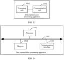
- an embodiment of this application provides a data transmission processing apparatus, including a processing unit and/or a communication unit corresponding to the method according to any one of the foregoing aspects.
- an embodiment of this application provides a data transmission processing apparatus, including a processor, a memory, and a communication interface.
- the processor is configured to store computer program code stored in the memory, to perform the method according to any one of the foregoing aspects.
- this application provides a chip.
- the chip includes a processor, configured to invoke instructions from a memory and run the instructions stored in the memory, so that a terminal device in which the chip is installed performs the method according to any one of the foregoing aspects.
- this application provides another chip.
- the chip may be a chip in a terminal device or an access network device.
- the chip includes an input interface, an output interface, and a processing circuit.
- the input interface, the output interface, and the circuit are connected through an internal connection path.
- the processing circuit is configured to perform the method according to any one of the foregoing aspects.
- this application provides another chip.
- the chip includes an input interface, an output interface, and a processor.
- the chip further includes a memory.
- the input interface, the output interface, the processor, and the memory are connected through an internal connection path.
- the processor is configured to execute code in the memory. When the code is executed, the processor is configured to perform the method according to any of the foregoing aspects.
- this application provides a chip system.
- the chip system includes at least one processor, a memory, and an interface circuit.
- the memory, a transceiver, and the at least one processor are interconnected through a line.
- the at least one memory stores instructions. When the instructions are executed by the processor, the method according to any one of the foregoing aspects is implemented.
- this application provides a computer-readable storage medium.
- the computer-readable storage medium stores instructions.
- the instructions When the instructions are run on a computer, the computer is enabled to perform the method according to any one of the foregoing aspects.
- this application provides a computer program product.
- the computer program product is configured to store a computer program.
- the computer program is run on a computer, the computer is enabled to perform the method according to anyone of the foregoing aspects.
- an embodiment of this application provides a communication system, including the terminal device and the access network device in any one of the foregoing aspects.
- Embodiments of this application may be applied to a communication system in which multiple radio access technologies (radio access technologies, RATs) dual connectivity (multiple RATs dual connectivity, MR-DC) is used and/or carrier aggregation (carrier aggregation, CA) is used.
- RATs radio access technologies
- MR-DC multiple RATs dual connectivity
- CA carrier aggregation
- embodiments of this application may alternatively be applied to another communication system in which a same data packet may be sent through a plurality of transmission paths. This is not limited.
- an MR-DC communication system may include a core network, a master node (master node, MN), a secondary node (secondary node, SN), and a terminal device.
- MN master node
- SN secondary node
- the MN may also be referred to as a master station, an anchor (anchor), a master network device, a master access network device, or the like.
- the SN may also be referred to as a secondary station, a secondary network device, a secondary access network device, or the like. Names of the MN and the SN are not limited in embodiments of this application.
- the MN is a radio access network (radio access network, RAN) device, and provides terminations (terminations) of a user plane (user plane) protocol stack and a control plane (control plane) protocol stack of a wireless communication air interface for the terminal device.
- the SN is also a RAN device, and provides terminations of a user plane and a control plane of a wireless communication air interface for the terminal device.
- the MN and the SN may be RAN devices supporting different wireless communication technologies, or may be RAN devices supporting a same wireless communication technology.
- the Wireless communication technology may include but is not limited to: a global system for mobile communications (global system for mobile communications, GSM), a general packet radio service (general packet radio service, GPRS), a universal mobile telecommunications system (universal mobile telecommunications system, UMTS), code division multiple access (code division multiple access, CDMA), wideband code division multiple access (wideband code division multiple access, WCDMA), time-division code division multiple access (time-division code division multiple access, TD-SCDMA), evolved universal terrestrial radio access (evolved universal terrestrial radio access, E-UTRA), next radio (next radio, NR) communication, a wireless local area network (wireless local area network, WLAN), a future 5G (the fifth generation) wireless communication system, or the like.
- GSM global system for mobile communications
- GPRS general packet radio service
- UMTS universal mobile telecommunications system
- code division multiple access code division multiple access
- CDMA wideband code division multiple access
- WCDMA wideband code division multiple access
- the MN may communicate with the core network on a control plane and a data plane.
- the SN may communicate with the core network on the control plane by using the MN.
- the SN may communicate with the core network on the data plane by using the MN, as shown in (a) in FIG. 1
- the SN may communicate with the core network on the data plane without using the MN, as shown in (b) in FIG. 1 .
- the RAN device in embodiments of this application may also be referred to as an access network device, or the like.
- the RAN device may be referred to as an access network device below.
- the access network device may be an access network device in a fifth-generation (5th-generation, 5G) mobile communication system, for example, a next generation NodeB (generation NodeB, gNB), may be an access network device in a long term evolution (Long Term Evolution, LTE) system, for example, an evolved NodeB (evolved NodeB, eNB), or may be a radio network controller (radio network controller, RNC), a NodeB (NodeB, NB), a base station controller (base station controller, BSC), a base transceiver station (base transceiver station, BTS), a home base station (for example, home evolved NodeB, or home NodeB, HNB), a baseband unit (baseband unit, BBU), a transmission reception point (transmission reception point, TRP
- the terminal device in embodiments of this application is a device with a wireless transceiver function, and may be referred to as a terminal (terminal), user equipment (user equipment, UE), a mobile station (mobile station, MS), a mobile terminal (mobile terminal, MT), an access device, a vehicle-mounted device, an industrial control device, a UE unit, a UE station, a mobile station, a remote station, a remote device, a mobile device, a UE terminal, a wireless communication device, a UE agent, a UE apparatus, or the like.
- the terminal device may be fixed or movable. It should be noted that the terminal device may support at least one wireless communication technology, such as LTE, NR, or WCDMA.
- the terminal device may be a mobile phone (mobile phone), a pad (pad), a desktop computer, a laptop computer, a palmtop computer, a mobile internet device (mobile internet device, MID), a wearable device, an all-in-one machine, a vehicle-mounted terminal, a virtual reality (virtual reality, VR) terminal device, an augmented reality (augmented reality, AR) terminal device, a wireless terminal in industrial control (industrial control), a wireless terminal in self driving (self driving), a wireless terminal in remote medical surgery (remote medical surgery), a wireless terminal in a smart grid (smart grid), a wireless terminal in transportation safety (transportation safety), a wireless terminal in a smart city, a wireless terminal in a smart home (smart home), a cellular phone, a cordless phone, a session initiation protocol (session initiation protocol, SIP) phone, a wireless local loop (wireless local loop, WLL) station, a personal digital assistant (personal digital assistant, PDA), a handheld device having a wireless
- a communication system in which a dual-connectivity architecture is used includes but is not limited to the following four types:
- the EN-DC (E-UTRA NR DC) may also be referred to as an option 3 series (Option 3 series), in other words, the core network is an evolved packet core (evolved packet core, EPC), the MN is an access network device in long term evolution (long term evolution, LTE), and the SN is an access network device in NR.
- EPC evolved packet core
- LTE long term evolution
- LTE long term evolution
- SN an access network device in NR.
- An example in which the access network device in LTE is an eNB (that is, the MN)
- the access network device in NR is a gNB (that is, the SN) is used for description.
- There is an X2 interface between the eNB and the gNB at least a control plane connection is included, and a user plane connection may be further included.
- S1 interface between the eNB and the EPC, at least a control plane connection is included, and a user plane connection may be further included.
- S1-U interface between the gNB and the EPC, that is, only a user plane connection can be included.
- EN-DC E-UTRA NR DC
- the NE-DC is also referred to as an option 4 series (Option 4 series), in other words, the core network is a 5G core (5G core, 5GC), the MN is an access network device in LTE, and the SN is an access network device in NR.
- 5G core 5G core
- 5GC 5G core
- LTE 5G core
- LTE Long Term Evolution
- gNB gNode B
- NG interface between an eNB base station and the 5GC, at least a control plane connection is included, and a user plane connection may be further included.
- NG-U interface between the gNB and the 5GC, that is, only a user plane connection can be included.
- NG EN-DC Next Generation E-UTRA NRDC
- the NG EN-DC is also referred to as an option 7 series (Option 7 series), in other words, the core network is a 5GC, the MN is an access network device in LTE, and the SN is an access network device in NR.
- There is an Xn interface between the gNB and the eNB at least a control plane connection is included, and a user plane connection may be further included.
- There is an NG interface between the gNB and the 5GC at least a control plane connection is included, and a user plane connection may be further included.
- There is an NG-U interface between the eNB and the 5GC that is, only a user plane connection can be included.
- the EN-DC, the NE-DC, and the NG EN-DC are all dual connectivity between the access network device in LTE and the access network device in NR, and may be referred to as dual connectivity between LTE and NR for short.
- the NR-NR DC may be understood as NR-to-NR dual connectivity
- the core network is a 5GC
- both the MN and the SN are an access network device (for example, the gNB) in NR.
- the terminal device may simultaneously access at least one access network device.
- the access network device is an MN of the terminal device.
- the terminal device accesses two or more access network devices, one of the two or more access network devices is the MN of the terminal device, and the other one or more access network devices are an SN/SNs of the terminal device.
- An air interface resource in embodiments of this application may include one or more serving cells provided by the access network device (for example, the MN or the SN) for the terminal device.
- One or more cells provided by the MN for the terminal device may be referred to as a master cell group (master cell group, MCG), and one or more cells provided by the SN for the terminal device may be referred to as a secondary cell group (secondary cell group, SCG).
- MCG master cell group
- SCG secondary cell group
- the access network device in LTE is an eNB
- the access network device in NR is a gNB.
- MCGs in the EN-DC, the NE-DC, the NG EN-DC, and the NR-NR DC are respectively the eNB, the eNB, the gNB, and the master gNB.
- SCGs are respectively the gNB, the gNB, the eNB, and the secondary gNB.
- An NR wireless protocol stack is divided into two planes: a user plane (user plane, UP) and a control plane (control plane, CP).
- a control plane protocol stack is a protocol cluster used for control signaling transmission of a system
- a user plane protocol stack is a protocol cluster used for user data transmission.
- the user plane protocol stack in NR has one extra service data adaptation protocol (service data adaptation protocol, SDAP) layer.
- SDAP service data adaptation protocol
- a user plane protocol stack is in the following sequence from top to bottom: an SDAP layer, a packet data convergence protocol (packet data convergence protocol, PDCP) layer, a radio link control (radio link control, RLC) layer, a media access control (media access control, MAC) layer, a physical (physical, PHY) protocol layer.
- PDCP packet data convergence protocol
- RLC radio link control
- media access control media access control
- PHY physical (physical, PHY) protocol layer.
- the SDAP layer is configured by using radio resource control (radio resource control, RRC) signaling, and the SDAP layer is responsible for mapping a quality of service (quality of service, QoS) flow to a corresponding data radio bearer (data radio bearer, DRB).
- RRC radio resource control
- QoS quality of service
- DRB data radio bearer
- the PDCP layer is responsible for compressing and decompressing an internet protocol (internet protocol, IP) header, transmitting user data and maintaining a sequence number (sequence number, SN) (indicating a sending sequence of data packets) of a radio bearer, and processing an RRC message on the control plane and an IP packet on the user plane.
- IP internet protocol
- SN sequence number
- a PDCP sublayer may perform header compression and encryption on the IP data packet, and then deliver the IP data packet to an RLC sublayer.
- the PDCP sublayer may further provide an in-order submission function and a duplicate packet detection function for the upper layer based on an SN of a PDCP data packet.
- a basic procedure in which a PDCP entity (entity) serves as a transmitting end includes the following six steps: Step 1: Buffer a received PDCP service data unit (service data unit, SDU) in a PDCP transmission buffer (buffer), set a dedicated time-out timer (discard timer) for the PDCP SDU, and assign a sequence number to each data packet in a sequence the data packet arrives at the PDCP layer.
- Step 1 Buffer a received PDCP service data unit (service data unit, SDU) in a PDCP transmission buffer (buffer), set a dedicated time-out timer (discard timer) for the PDCP SDU, and assign a sequence number to each data packet in a sequence the data packet arrives at the PDCP layer.
- the PDCP SDU includes control plane data from an RRC layer or user plane data from the SDAP layer.
- the time-out timer is used to detect whether the PDCP SDU is successfully sent. When preset duration of the time-out timer expires, or when a status report (Status Report) indicating that the PDCP SDU is successfully received is received, it may be determined that the PDCP SDU has been sent, and the PDCP entity needs to discard the PDCP SDU and a corresponding PDCP PDU.
- Step 2 The PDCP entity performs header compression processing on the user plane data.
- Step 2 is optional, the PDCP entity performs header compression processing only on the user plane data, but does not perform header compression processing on the control plane data.
- Step 3 The PDCP entity performs integrity protection on the control plane data or the user plane data based on an integrity protection algorithm.
- the PDCP entity performs integrity protection on the control plane data or the user plane data, and may generate a verification code called MAC-I, so that a receiving end performs an integrity check. Integrity protection is always needed for the control plane data, and an integrity protection function for the user plane data is optional.
- Step 4 The PDCP entity performs encryption on the control plane data or the user plane data.
- Step 4 is optional. That the PDCP entity performs encryption on the control plane data or the user plane data may ensure security of data transmission between the transmitting end and the receiving end.
- Step 5 Add a PDCP header and generate a PDCP PDU.
- Step 6 Send the PDCP PDU to an RLC layer.
- the terminal device When switching from a connected state to a third state (that is, an inactive state, inactive), the terminal device performs a suspension operation on the PDCP entity.
- the PDCP entity serving as a transmitting end discards all stored PDCP PDUs, and sets a transmitting end variable (TX _NEXT) to an initial value, that is, 0.
- TX _NEXT transmitting end variable
- the PDCP entity serving as a transmitting end does not discard stored SDUs (referred to as suspended PDCP SDUs below). In this way, after the terminal device enters the connected state, these data packets can be provided with transmission opportunities, to avoid data packet loss in a state switching process.
- the PDCP entity serving as a receiving end stops and resets a running reordering timer (t_Reordering).
- the reordering timer is used to detect whether the PDCP PDU is successfully received. If the PDCP PDU is not received within a time specified by the reordering timer, the receiving end considers that the PDCP PDU has been lost.
- the PDCP entity serving as a receiving end waits for an arrival of an out-of-order PDCP PDU.
- the PDCP entity When the reordering timer expires, the PDCP entity does not wait for the out-of-order PDCP PDU, but delivers a received PDCP PDU to the upper layer (in other words, delivers the control plane data to the RRC layer, and delivers the user plane data to the SDAP layer) in ascending order of SNs.
- the PDCP entity when the terminal device performs the suspension operation on the PDCP entity, the PDCP entity no longer transmits data.
- the PDCP entity serving as a transmitting end discards all stored PDCP PDUs, stores suspended PDCP SDUs, and sets the transmitting end variable to the initial value.
- the PDCP SDU After the terminal device enters the connected state, the PDCP SDU may be reprocessed to generate a PDCP PDU, and data may be transmitted upward in a new sequence. This can avoid data packet loss in the state switching process.
- the PDCP entity serving as a receiving end stops and resets the running reordering timer, so that the data may be sequentially delivered to the upper layer in a previous order after the terminal device enters the connected state. In conclusion, after the terminal device enters the connected state, the PDCP entity transmits data that is not transmitted. This improves data transmission efficiency.
- the access network device may configure whether a PDCP layer of a radio bearer (radio bearer, RB) of the terminal device needs to duplicate data of the PDCP entity, and send the duplicated data separately through two or more different paths (for example, two different RLC entities).
- Radio bearer radio bearer
- Different RLC entities correspond to different logical channels.
- the RLC may communicate with the PDCP layer through a service access point (service access point, SAP), or may communicate with the MAC layer through a logical channel.
- SAP service access point
- Each logical channel of each terminal device has an RLC entity.
- a PDCP data duplication function may be indicated to be started (that is, activated) or stopped (that is, deactivated) by using control signaling (control element, CE) of the MAC layer.
- CE control signaling
- the access network device may configure whether the PDCP data duplication function is started immediately after configuration is completed.
- the RLC entity is in an active state, the PDCP entity may send data to the RLC entity.
- the access network device may configure a plurality of signaling radio bearers (signaling radio bearers, SRBs), for example, an SRB 1 and an SRB 2 configured on the MCG and an SRB 3 configured on the SCG, for the terminal device.
- SRBs signaling radio bearers
- a split bearer whose PDCP is terminated at an MN may also be referred to as an MN terminated split bearer, and may be referred to as an MN bearer for short.
- a split bearer whose PDCP is terminated at an SN may also be referred to as an SN terminated split bearer, and may be referred to as an SN bearer for short.
- split bearer split bearer
- duplicate bearer duplicate bearer
- the split bearer may be understood as a radio bearer that may be associated with two or more transmission paths, that is, data on one split bearer may be transmitted through one or more of transmission paths associated with the split bearer.
- a maximum quantity of transmission paths that may be associated with one split bearer is related to a quantity of SNs accessed by the terminal device.
- each of two or more transmission paths associated with a same split bearer is associated with air interface resources of different access network devices. For example, if the terminal device accesses one MN and one SN, when a split bearer is associated with a first transmission path and a second transmission path, the first transmission path may be associated with an air interface resource of the MN, and the second transmission path may be associated with an air interface resource of the SN. For example, as shown in FIG.
- the terminal device may be connected to one MN and one SN, and a quantity of transmission paths associated with one split bearer is 2.
- a PDCP #3 may transmit data through an RLC #3, or may transmit data through an RLC #6.
- the PDCP may split to-be-transmitted data into a plurality of pieces of sub-data, transmit partial sub-data through an MN RLC in the MCG, and transmit remaining sub-data through an SN RLC in the SCG.
- one PDCP entity is associated with at least two RLC entities of the MCG and the SCG.
- the terminal device delivers PDCP data to the RLC entity associated with the MCG or the RLC entity associated with the SCG depends on an uplink data threshold configured by the access network device.
- the terminal device may determine to deliver the PDCP data to the RLC entity associated with the MCG or the RLC entity associated with the SCG.
- the terminal device can only deliver the PDCP data to a primary RLC entity.
- the primary RLC entity may be the RLC entity associated with the MCG, or may be the RLC entity associated with the SCG, and is indicated by the access network device. If a sub-data packet of a same service is separately transmitted through the primary RLC entity and a secondary RLC entity, a data transmission throughput is improved.
- the duplicate bearer may be understood as that duplicated data (for example, an RRC message) may be transmitted on two or more transmission paths associated with one split bearer. This helps improve reliability of data transmission between the access network device and the terminal device.
- the RLC layer communicates with the PDCP layer (or the RRC layer) through an RLC channel (RLC channel), and communicates with the MAC layer through the logical channel.
- RLC configuration is logical channel-level configuration, and one RLC entity corresponds to only one logical channel of one terminal device.
- Data received by the RLC entity from the PDCP layer or data sent by the RLC entity to the PDCP layer is referred to as an RLC SDU (or the PDCP PDU).
- RLC PDU or a MAC SDU
- the RLC layer includes a transmission mode (transparent mode, TM), an acknowledged mode (acknowledged mode, AM), and an unacknowledged mode (unacknowledged mode, UM).
- the RLC layer is mainly responsible for performing, in the acknowledged mode (acknowledged mode, AM) and the unacknowledged mode (unacknowledged mode, UM), segmentation/reassembly (segmentation/reassembly) on the RLC SDU, reassembly on the RLC SDU, and discarding and processing on reassembled RLC SDUs, and performing, in the AM mode, error correction by using an automatic repeat-request (automatic repeat-request, ARQ), duplicated packet detection (duplicate detection), re-segmentation (re-segmentation) on an RLC SDU segment, and protocol error detection.
- the RLC layer may be further used to transmit an upper-layer PDU and reestablish the RLC layer.
- the RLC entity When the terminal device performs a suspension operation on the RLC entity, the RLC entity no longer transmits data.
- the RLC entity serving as a transmitting end discards all stored RLC PDUs, stores the suspended RLC SDU, and sets the transmitting end variable to the initial value.
- the RLC SDU After the terminal device enters the connected state, the RLC SDU may be reprocessed to generate an RLC PDU, and data may be transmitted upward in a new sequence. This can avoid data packet loss in the state switching process.
- the RLC entity serving as a receiving end stops and resets the running reordering timer, so that the data may be sequentially delivered to the upper layer in a previous order after the terminal device enters the connected state. In conclusion, after the terminal device enters the connected state, the RLC entity transmits data that is not transmitted. This improves data transmission efficiency.
- the MAC layer is mainly responsible for mapping, multiplexing, and demultiplexing between a logical channel and a transmission channel, reporting scheduling information, performing error correction by using a hybrid automatic repeat request (hybrid automatic repeat request, HARQ), managing priorities between users through dynamic scheduling, and managing priorities of logical channels.
- HARQ hybrid automatic repeat request
- the SDAP layer maps the QoS flow to a DRB, to determine a bearer corresponding to the QoS flow.
- the bearer may be one of an MCG bearer, an SCG bearer, or a split bearer.
- the QoS flow is sent to the MN or the SN by using a corresponding PDCP entity, an RLC entity, and a MAC entity.
- the terminal device detects signal quality of each communication link.
- the terminal device detects whether a connection failure event occurs on a link between the terminal device and each access network device. For example, the terminal device detects whether a connection failure occurs on a link between the terminal device and the MCG, and whether a connection failure occurs on a link between the terminal device and the SCG.
- that the terminal device detects that the connection failure occurs on the link between the terminal device and the MCG may be referred to as determining that the MCG connection failure event occurs, and that the terminal device detects that the connection failure occurs on the link between the terminal device and the SCG may be referred to as determining that the SCG connection failure event occurs.
- determining that the MCG connection failure event occurs may also be referred to as detecting that the MCG connection failure event occurs.
- the determining that the SCG connection failure event occurs may also be referred to as detecting that the SCG connection failure event occurs.
- the MCG connection failure event may include that a connection failure occurs on a link between the terminal device and a primary cell (primary cell, PCell) in the MCG or a special cell (Special Cell, SpCell) in the MCG, or include that a connection failure occurs on links between the terminal device and all cells in the MCG.
- the SCG connection failure event may include that a connection failure occurs on a link between the terminal device and a secondary cell (secondary cell, SCell) in the SCG or a SpCell in the SCG, or include that a connection failure occurs on links between the terminal device and all cells in the SCG.
- the MCG connection failure event or the SCG connection failure event includes at least one of the following: a radio link failure (radio link failure, RLF), a handover failure (handover failure, HOF), an integrity check failure (integrity check failure), an RRC reconfiguration failure, and the like. This is not limited in embodiments of this application.
- the RLF includes the following four cases:
- the out-of-sync indication may be information reported when the terminal device detects that channel quality of a physical downlink control channel (physical downlink control channel, PDCCH) or a physical downlink shared channel (physical downlink shared channel, PDSCH) is lower than a threshold in a time window.
- the in-sync indication may be information reported when the terminal device detects a channel instruction of the PDCCH or the PDSCH is higher than a threshold in a time window. It may be understood that the out-of-sync indication may be understood as poor channel quality, and the in-sync indication may be understood as good channel quality.
- the terminal device detects that the quantity of consecutive out-of-sync indications is greater than a threshold, or no in-sync indication is received within preset duration it may indicate the radio link failure.
- the terminal device detects that a random access problem occurs.
- the random access problem occurs, for example, when a quantity of random access failures is greater than a threshold, and it may be considered that the RLF occurs on a current communication link.
- the terminal device detects that a quantity of RLC retransmissions reaches the maximum.
- the maximum quantity of RLC retransmissions is not limited in this application.
- an RLC SDU is transmitted for a plurality of times but is still not successfully transmitted, it may be considered that the RLF occurs on the current communication link.
- the terminal device fails to preempt a channel for a plurality of consecutive times, it may be considered that the RLF occurs on the current communication link.
- a cause of the HOF includes but is not limited to one of the following: insufficient transmission resources, no configuration of a network path (IPPATH), a configuration error of a neighboring node in an IPPATH, and the like. If the terminal device cannot successfully access a target cell within specified duration after receiving a handover instruction, it may be considered that the HOF occurs.
- the integrity check failure means that the terminal device fails to perform an integrity check on a data packet of an SRB or a DRB configured by the access network device.
- the integrity check failure exists, it is considered that content of the data packet may be tampered with by an attacker. In this case, the current link is unreliable and the access network device needs to be notified.
- the RRC reconfiguration failure means that when the access network device delivers an RRC reconfiguration message used to configure or reconfigure an MCG and/or an SCG, the terminal device cannot perform a configuration operation based on configuration information in the RRC reconfiguration message.
- the RRC reconfiguration message includes but is not limited to one of the following: at least one piece of configuration information does not match a capability of the terminal device, terminal identity information indicated by at least one piece of configuration information does not match the terminal device, and the like.
- FIG. 4 is a schematic flowchart of a method of an SCG connection failure event in the conventional technology. As shown in FIG. 4 , the method includes the following steps S401 to S406.
- a terminal device detects that an SCG connection failure event occurs.
- the terminal device suspends (suspends) a transmission link of an SCG.
- the transmission link of the SCG suspended by the terminal device includes all SRBs and DRBs carried by the SCG.
- by resetting a MAC entity of the SCG it can be ensured that the transmission link of the SCG is suspended. It may be understood that, when detecting that the SCG connection failure event occurs, the terminal device suspends the transmission link of the SCG. This can directly avoid using the SCG to communicate with an SN.
- the terminal device reports SCG failure information (SCG failure information) to a master node (MN).
- SCG failure information SCG failure information
- MN master node
- the SCG failure information may be an RRC message, and may include a failure type of an occurred SCG connection failure event.
- the failure type is: an RLF, a HOF, an integrity check failure, an RRC connection reconfiguration failure, or that consecutive out-of-sync indications are detected, no in-sync indication is received for a long time, a random access problem occurs, a quantity of RLC retransmissions reaches the maximum, or continuous LBT failures in the RLF. This is not limited herein.
- the SCG failure information may further carry a measurement result, to help the MN make a decision.
- the measurement result may be a measurement result of at least one frequency associated with the SCG, for example, a measurement result of a neighboring cell of a serving cell of the SCG at a given frequency.
- the master node performs SCG failure resumption.
- the MN may resume a communication link between a UE and the SCG by releasing the transmission link of the SCG, triggering a handover process to change a primary cell of the SCG, or the like. It may be understood that, when the terminal device does not detect an MCG connection failure event, it may be determined that no connection failure occurs on an air interface link of an MCG. Therefore, the SCG failure resumption is performed by using an MN corresponding to the MCG, and a failure resumption success rate can be improved.
- S405 The master node sends SCG resumption information to the terminal device.
- the SCG resumption information indicates that the SCG connection failure event is resumed, indicates the terminal device to perform an SCell change, or the like. This is not limited herein.
- the SCG resumption information may be an RRC message, for example, an RRC reconfiguration message.
- the terminal device resumes (resumes) the transmission link of the SCG.
- That the terminal device resumes the transmission link of the SCG includes resuming all SRBs and DRBs carried by the SCG.
- the method further includes: Reestablish a PDCP entity if the terminal device changes a key of the SCG.
- the method further includes: The terminal device reestablishes an RLC entity of the SCG.
- the terminal device When the terminal device reestablishes the RLC entity of the SCG, all RLC data is discarded.
- the data includes an RLC SDU, a segment of the RLC SDU, and an RLC PDU, so that an RLC status of the terminal device is consistent with that of a serving cell of a new SCG.
- the PDCP entity and the RLC entity of the SCG still work normally.
- the PDCP entity normally processes to-be-sent data and delivers a PDCP PDU to the RLC entity of the SCG.
- the RLC entity of the SCG also normally processes data, and waits for a MAC layer for scheduling and sending.
- processed data at an RLC layer of the SCG cannot be sent in time. This causes a data transmission failure.
- the terminal device discards all RLC data. As a result, data that is started to be or has been processed at the RLC layer in an SCG failure resumption process is lost.
- FIG. 5 is a schematic flowchart of a method of an MCG connection failure event in the conventional technology. As shown in FIG. 5 , the method includes the following steps S501 to S507.
- a terminal device detects that an MCG connection failure event occurs.
- the terminal device suspends (suspends) a transmission link of an MCG.
- the transmission link of the MCG suspended by the terminal device includes all SRBs and DRBs carried by the MCG.
- by setting a MAC entity of the MCG it can be ensured that the transmission link of the MCG is suspended. It may be understood that, when detecting that the MCG connection failure event occurs, the terminal device suspends the transmission link of the MCG. This may directly avoid using the MCG to communicate with an MN.
- the terminal device sends MCG failure information (MCG failure information) to a secondary node (SN).
- MCG failure information MCG failure information
- SN secondary node
- the MCG failure information may be reported by using a signaling radio bearer configured by the MN.
- the signaling radio bearer may be a dedicated signaling bearer for transmitting an RRC message between the terminal device and the SN, for example, an SRB3.
- the MCG failure information may be an RRC message, and may include a failure type of an occurred MCG connection failure event.
- the failure type is: an RLF, a HOF, an integrity check failure, an RRC connection reconfiguration failure, or that consecutive out-of-sync indications are detected, no in-sync indication is received for a long time, a random access problem occurs, a quantity of RLC retransmissions reaches the maximum, or continuous LBT failures in the RLF.
- the MCG failure information may further carry a measurement result, to help the MN make a decision.
- the measurement result may be a measurement result of at least one frequency associated with the MCG, for example, a measurement result of a neighboring cell of a serving cell of the MCG at a given frequency, and optionally, may carry a measurement result of at least one frequency associated with an SCG, for example, a measurement result of a neighboring cell of a serving cell of the SCG at a given frequency.
- the secondary node sends the MCG failure information to a master node (MN).
- MN master node
- the SN forwards the MCG failure information to the MN.
- the master node performs MCG failure resumption.
- the MN may resume a communication link between the terminal device and the MCG by releasing the transmission link of the MCG, triggering a handover process to change a primary cell of the MCG, or the like.
- the master node sends MCG resumption information to the terminal device.
- the MCG resumption information indicates that the MCG connection failure event is resumed, indicates the terminal device to perform a PCell change, or the like. This is not limited herein.
- the MCG resumption information may be an RRC message, for example, an RRC reconfiguration message.
- the terminal device resumes (resumes) the transmission link of the MCG.
- That the terminal device resumes the transmission link of the MCG includes resuming all SRBs and DRBs carried by the MCG.
- the method further includes: Reestablish a PDCP entity if the terminal device changes a key of the MCG.
- the method further includes: The terminal device reestablishes an RLC entity of the MCG.
- the terminal device When the terminal device reestablishes the RLC entity of the MCG, all RLC data is discarded.
- the data includes an RLC SDU, a segment of the RLC SDU, and an RLC PDU, so that an RLC status of the terminal device is consistent with that of a serving cell of a new MCG.
- the terminal device suspends the transmission link of the MCG
- the PDCP entity and the RLC entity in the MCG still work normally.
- the PDCP entity normally processes to-be-sent data and delivers a PDCP PDU to the RLC entity of the MCG.
- the RLC entity of the MCG also normally processes data, and waits for a MAC layer for scheduling and sending.
- processed data at an RLC layer of the MCG cannot be sent in time. This causes a data transmission failure.
- the terminal device discards all RLC data. As a result, data that is started to be or has been processed at the RLC layer in an MCG failure resumption process is lost.
- the MN may send, to the terminal device, information (for example, the SCG resumption information described in step S405) indicating that the SCG connection failure event is resumed.
- the MN may send, to the terminal device, information (for example, the MCG resumption information described in step S506) indicating that the MCG connection failure event is resumed.
- the access network device controls, based on a network condition or a requirement of the terminal device, the SCG to perform a deactivation operation. For example, when a data rate requirement of the terminal device changes (for example, the rate requirement changes from high to low), or considering power consumption of communication between the terminal device and the access network device, the access network device allows to perform the deactivation operation on the SCG. In other words, when the terminal device does not require a high data rate requirement, and/or power consumption of the terminal device needs to be further reduced, the access network device may deactivate a configured SCG, so that the terminal device temporarily disconnects a communication link with the SCG, and maintains data communication only by using the MCG. Once the data rate requirement of the terminal device changes from low to high, the access network device may reactivate the SCG that is already in a deactivated state, to resume the communication link between the terminal device and the SCG.
- a data rate requirement of the terminal device changes (for example, the rate requirement changes from high to low)
- the access network device allows
- FIG. 6 is a flowchart of a method of an SCG deactivation event or activation event in the conventional technology. As shown in FIG. 6 , the method includes steps S601 and S602.
- a terminal device sends auxiliary information to an access network device.
- Step S601 is optional, and the auxiliary information may be used to assist the access network device (the following access network device in this application may be an MN, an SN, or the like, this is not limited herein) in determining whether the terminal device performs an SCG deactivation operation.
- a type of the auxiliary information may be at least one of an RRC message, a MAC message, a physical layer message, or the like. This is not limited herein.
- a form of the auxiliary information is not limited in this application, and the auxiliary information may include the following three forms.
- the first form is a data buffer report which indicates a current volume of to-be-sent data of the terminal device.
- the volume of to-be-sent data may be a volume of to-be-sent data of at least one logical channel group configured by the access network device for the terminal device, or may be a volume of to-be-sent data of all logical channel groups configured by the access network device for the terminal device.
- the at least one logical channel group may be a logical channel group configured by the access network device.
- the volume of to-be-sent data of the logical channel group may be obtained by configuring by the access network device by using a buffer status report (buffer status report, BSR).
- BSR buffer status report
- the second form is a status indication of a volume of to-be-sent data, which indicates a current status of the volume of to-be-sent data of the terminal device.
- a high/medium/low indication reflects a status of a current volume of to-be-sent data.
- the third form is a status indication of power consumption, which indicates a current power consumption status or an expected power consumption level of the terminal device. For example, the current power consumption of the terminal device is high, or a current power consumption level is expected to be reduced.
- the access network device sends a deactivation instruction or an activation instruction to the terminal device.
- an SCG deactivation instruction information indicating that an SCG is in a deactivated state
- information indicating that the SCG is in an active state may be referred to as an SCG activation instruction. That is, after receiving the SCG deactivation instruction, the terminal device performs an operation of deactivation on the SCG. After receiving the SCG activation instruction, the terminal device performs an operation of activation on the SCG.
- that the terminal device receives the SCG deactivation instruction sent by the access network device may be referred to as determining that an SCG deactivation event occurs, and that the terminal device receives the SCG activation instruction sent by the access network device may be referred to as determining that the SCG deactivation event is resumed.
- the access network device that sends the SCG deactivation instruction and the SCG activation instruction to the terminal device may be the MN or the SN, and access network devices that send the SCG deactivation instruction and the SCG activation instruction may be the same or different. This is not limited herein.
- the access network device that receives the auxiliary information and the access network device that sends the SCG deactivation instruction or the SCG activation instruction are the same access network device, or may be different access network devices in an actual scenario.
- Types of the SCG deactivation instruction and the SCG activation instruction may be at least one of an RRC message, a MAC message (for example, a MAC CE), or a physical layer message (for example, downlink control signaling (downlink control information, DCI)) or the like.
- the SCG deactivation instruction may include an SCG deactivation indication, for example, carrying a displayed information element to indicate the SCG to perform a deactivation operation.
- the SCG deactivation indication may further carry at least one cell identifier or cell set identifier configured by the SCG, and indicates the at least one cell or cell set of the SCG to perform the deactivation operation or a hibernation operation.
- the SCG activation instruction may include an SCG activation indication, for example, carrying a displayed information element to indicate the SCG to perform an activation operation.
- the SCG activation indication may further carry at least one cell identifier or cell set identifier configured by the SCG, and indicates the at least one cell or cell set of the SCG to perform the activation operation.
- a method for processing the SCG deactivation event and a method for processing resumption of the SCG deactivation event have not been defined. If reference is made to a method for processing an SCG connection failure event, a transmission link of the SCG is suspended. As a result, processed data at an RLC layer of the SCG cannot be sent in time. This causes a data transmission failure. If reference is made to a method for processing resumption of the SCG connection failure event, data that is started to be or has been processed at the RLC layer in an SCG failure resumption process is lost.
- the target event may be the SCG connection failure event, the MCG connection failure event, or the SCG deactivation event.
- the target event may be a connection failure event between an access network device and a terminal device in another multi-connectivity architecture, a deactivation event that occurs in a cell in a single access network device, or the like. This is not limited herein.
- the first cell group may be understood as a cell group that performs data transmission in the target event, or may be understood as a cell group that may be suspended.
- a first cell group corresponding to the SCG connection failure event and the SCG deactivation event is an SCG
- a first cell group corresponding to the MCG connection failure event is an MCG.
- Access network devices corresponding to the second cell group and the first cell group are different, that is, the first cell group and the second cell group correspond to different access network devices.
- the second cell group may be the MCG
- the second cell group may be the SCG.
- the target PDCP entity may be all PDCP entities associated with the first cell group.
- the target PDCP entity when the first cell group is the MCG, the target PDCP entity may be at least one of a PDCP #1, a PDCP #2, or a PDCP #3.
- the target PDCP entity When the first cell group is the SCG, the target PDCP entity may be at least one of a PDCP #4, a PDCP #5, or a PDCP #6.
- the target PDCP entity may be a PDCP entity specified by the access network device (for example, the MN or the SN) in the first cell group by using signaling.
- the target PDCP entity may be a PDCP entity of a specified bearer type in the first cell group.
- the target PDCP entity is a PDCP entity of a split bearer or a duplicate bearer, or has a same type as the target event.
- the target PDCP entity is not limited in this application.
- a quantity of the target PDCP entities is not limited.
- the target PDCP entity when the first cell group is the MCG, the target PDCP entity may be at least one of the PDCP #1 or the PDCP #3.
- the target PDCP entity may be at least one of the PDCP #4 or the PDCP #6.
- the first RLC entity may be all RLC entities associated with the first cell group.
- the first RLC entity when the first cell group is the MCG, the first RLC entity may be at least one of the RLC #1, the RLC #2, the RLC #3, or the RLC #4.
- the first cell group is the SCG, the first RLC entity may be at least one of the RLC #5, the RLC #6, an RLC #7, or an RLC #8.
- the first RLC entity may be an RLC entity specified by the access network device (for example, the MN or the SN) in the first cell group by using signaling, or an RLC entity corresponding to the SCG connection failure event or the MCG connection failure event.
- the first RLC entity may be an RLC entity of a specified bearer type in the first cell group.
- the first RLC entity is an RLC entity associated with a split bearer or a duplicate bearer of the target PDCP entity in the first cell group, or has a same type as the target event.
- the first RLC entity is not limited in this application.
- a quantity of the first RLC entity entities is not limited. For example, as shown in FIG. 3 , when the first cell group is the MCG, the first RLC entity may be at least one of the RLC #1 or the RLC #3. When the first cell group is the SCG, the first RLC entity may be at least one of the RLC #5 or the RLC #8.
- an RLC entity that is in the second cell group and that is configured to transmit data of the target PDCP entity may be referred to as the second RLC entity.
- the second RLC entity may include any RLC entity in the second cell group.
- the second RLC entity when the first cell group is the MCG, the second RLC entity may be the RLC #5, the RLC #6, the RLC #7, or the RLC #8.
- the first cell group is the SCG
- the second RLC entity may be the RLC #1, the RLC #2, the RLC #3, or the RLC #4.
- the second RLC entity may be an RLC entity associated with a duplicate bearer of the target PDCP entity in the second cell group by the access network device (for example, the MN or the SN), or may include an RLC entity associated with a split bearer of the target PDCP entity in the second cell group by the access network device.
- the second RLC entity when the first cell group is the MCG, the second RLC entity may be the RLC #6.
- the second RLC entity may be the RLC #4.
- the second RLC entity may further include an RLC entity associated with a bearer corresponding to a target event in the second cell group by the access network device (for example, the MN or the SN).
- the second RLC entity is configured to carry data that is in the second cell group and that is different from data of an access network device corresponding to the first cell group.
- the target event is an SCG connection failure or the SCG deactivation event
- the second RLC entity is an RLC entity associated with a bearer of the MCG
- the second RLC entity may be the RLC #1 or the RLC #3
- the target event is an MCG connection failure
- the second RLC entity is an RLC entity associated with a bearer of the SCG
- the second RLC entity may be the RLC #5 or the RLC #8.
- the terminal device may control the target PDCP entity to send data to the RLC entity, and may separately transmit duplicated data by using the first RLC entity and the second RLC entity, to improve data transmission reliability.
- the terminal device may directly control, without considering an uplink data threshold, the target PDCP entity to send data to the second RLC entity.
- the target PDCP entity when a to-be-sent data volume of the terminal device is greater than or equal to the uplink data threshold, or when a to-be-sent data volume of the terminal device is less than the uplink data threshold, the target PDCP entity is controlled to send data to a primary RLC entity.
- the target PDCP entity may be controlled to send the data to the primary RLC entity.
- the terminal device may control the target PDCP entity to send the data to the second RLC entity.
- the terminal device may control the target PDCP entity to send data to the first RLC entity.
- the primary RLC entity and the uplink data threshold are specified by the access network device. If a sub-data packet of a same service is separately transmitted through the first RLC entity and the second RLC entity, a data transmission throughput is improved.
- the target entity may be a target PDCP entity or a first RLC entity in the first cell group.
- a quantity of target entities is not limited in this application.
- the target entities may be a plurality of target PDCP entities or a plurality of first RLC entities, or may be a target PDCP entity and a first RLC entity.
- the terminal device may send first indication information to the target entity.
- the first indication information indicates that the target event occurs, or indicates the target entity not to perform an operation of data transmission based on the first cell group, or indicates the target entity to perform an operation of data transmission based on the second cell group. That the target entity does not perform an operation of data transmission based on the first cell group is not limited in this application.
- the target entity receives the data, the data may not be transmitted, or the target entity may be suspended, so that the target entity does not receive the data and send the data.
- That the target entity performs an operation of data transmission based on the second cell group is not limited in this application, and it may indicate that the target PDCP entity performs data transmission based on the second RLC entity. It may be understood that, after receiving the first indication information, the target entity may be directly controlled by the terminal device based on the first indication information. This improves processing efficiency of the target entity.
- the terminal device may send the second indication information to the access network device.
- the second indication information indicates that the target event occurs, a type of the target event, or a measurement result of the terminal device.
- the type of the target event may be one of the SCG connection failure event, the MCG connection failure event, or the SCG deactivation event, or may be a connection failure type in the SCG connection failure event or the MCG connection failure event (for example, the failure type is an RLF, a HOF, an integrity check failure, an RRC connection reconfiguration failure, or that consecutive out-of-sync indications are detected, no in-sync indication is received for a long time, a random access problem occurs, a quantity of RLC retransmissions reaches the maximum, or continuous LBT failures in the RLF), or may be a type of the SCG deactivation event (for example, a lower data rate requirement or a lower power requirement).
- the access network device may determine, by using the second indication information, that the target event occurs on the terminal device and related information about the target event. This helps the access network device process the target event, and improves processing efficiency.
- An access network device that receives the second indication information is not limited in this application.
- the target event is the SCG connection failure event
- a transmission failure occurs when the terminal device sends information to the SN. Therefore, the access network device may be the MN, to notify the SN to perform MCG failure resumption.
- the target event is the MCG connection failure event
- a transmission failure occurs when the terminal device sends information to the MN. Therefore, the access network device may be the SN, and forward the second indication information to the MN by using the SN, to notify the MN to perform the MCG failure resumption.
- the target event is the SCG deactivation event
- the access network device may be the MN or the SN.
- the access network device may send third indication information to the terminal device.
- the third indication information indicates that the target event is resumed.
- An access network device that sends the third indication information is not limited in this application.
- the target event is the SCG connection failure event or the MCG connection failure event
- failure resumption is performed by an MN. Therefore, the access network device is the MN.
- the target event is the SCG deactivation event
- the access network device may be the MN or the SN.
- an access network device that receives auxiliary information sent by the terminal device sends the third indication information to the terminal device. It may be understood that, after receiving the third indication information, the terminal device may determine that the target event is resumed, to control the target entity to perform data transmission by using a transmission resource of a first cell group corresponding to the target event. This can avoid data loss.
- the terminal device may send fourth indication information to the target entity.
- the fourth indication information indicates that the target event is resumed, or indicates the target entity to perform the operation of data transmission based on the first cell group.
- the operation of data transmission performed by the target entity based on the first cell group is not limited in this application.
- Data transmission may be performed when the target entity receives the data, or the target entity may be resumed, so that the target entity receives the data and sends the data.
- the fourth indication information may also indicate the target entity to perform the operation of data transmission based on the second cell group.
- That the target entity performs an operation of data transmission based on the second cell group is not limited in this application, and it may indicate that the target PDCP entity performs data transmission based on the second RLC entity. It may be understood that, after receiving the fourth indication information, the target entity may be directly controlled by the terminal device based on the fourth indication information. This improves processing efficiency of the target entity. If the target entity can perform data transmission based on the first cell group and the second cell group, data transmission efficiency can be further improved.
- This embodiment of this application provides a data transmission processing method.
- the terminal device controls a target entity in the first cell group corresponding to the target event not to perform data transmission based on the first cell group.
- data transmission is not performed by using the transmission resource of the first cell group corresponding to the target event. This can prevent the first cell group from communicating with the access network device, to avoid a data transmission failure.
- the target entity is controlled to perform data transmission based on the first cell group. In other words, data transmission is performed by using a transmission resource corresponding to the target event. This can avoid data loss.
- FIG. 7 is a schematic flowchart of a first data transmission processing method according to an embodiment of this application. As shown in FIG. 7 , the method includes the following step S701 and step S702.
- a terminal device determines that a target event occurs.
- the target event includes an SCG connection failure event, an MCG connection failure event, or an SCG deactivation event.
- the target event may be a connection failure event between an access network device and a terminal device in another multi-connectivity architecture, a deactivation event that occurs in a cell in a single access network device, or the like.
- the terminal device may determine that the SCG connection failure event or the MCG connection failure event occurs.
- the terminal device may determine that the SCG deactivation event occurs.
- the method further includes: The terminal device sends second indication information to the access network device.
- the second indication information indicates that the target event occurs, a type of the target event, or a measurement result of the terminal device. For details, refer to the foregoing descriptions. Details are not described herein again.
- the target event is the SCG connection failure event
- an MN may resume a communication link between the terminal device and an SCG by releasing a transmission link of the SCG, triggering a handover process to change a primary cell of the SCG, or the like.
- the target event is the MCG connection failure event
- the MN may resume the communication link between the terminal device and the SCG by releasing a transmission link of the MCG, triggering a handover process to change a primary cell of the MCG, or the like.
- the terminal device controls a target entity not to perform data transmission based on a first cell group corresponding to the target event.
- That the target entity does not perform data transmission based on the first cell group corresponding to the target event may be understood as that a target PDCP entity does not send uplink data to a first RLC entity, or the first RLC entity does not send uplink data to a MAC entity in the first cell group.
- data transmission is not performed by using a transmission resource of the first cell group corresponding to the target event. For example, as shown in FIG.
- a PDCP #1 does not send the uplink data to an RLC #1 in the MCG, or an RLC #1 does not send the uplink data to a MAC #1 in the MCG. If the target event is the SCG connection failure event or the SCG deactivation event, a PDCP #2 does not send the uplink data to an RLC #2 in the SCG, or an RLC #2 does not send the uplink data to a MAC #2 in the SCG.
- a second RLC entity may further perform data transmission based on a source PDCP entity. For example, as shown in FIG. 8 , when the second RLC entity is the RLC #2, the second RLC entity may transmit uplink data from the PDCP #1 and uplink data from the PDCP #2.
- the terminal device when determining that the target event occurs, controls the target entity in the first cell group corresponding to the target event not to perform data transmission based on the first cell group. In other words, data transmission is not performed by using the transmission resource of the first cell group corresponding to the target event. This can prevent the first cell group from communicating with the access network device, to avoid a data transmission failure.
- the target entity is the target PDCP entity
- the method further includes: The terminal device controls the target PDCP entity to send data to the second RLC entity in a second cell group. Access network devices corresponding to the second cell group and the first cell group are different.
- the second RLC entity may include any RLC entity in the second cell group, and may specifically include an RLC entity associated with a bearer corresponding to the target event in the second cell group by the access network device (for example, the MN or an SN), may include an RLC entity associated with a target PDCP entity of a duplicate bearer in the second cell group by the access network device, or may include an RLC entity associated with a target PDCP entity of a split bearer in the second cell group by the access network device.
- the second RLC entity includes the RLC entity associated with the duplicate bearer of the target PDCP entity in the second cell group by the access network device.
- the terminal device controls the target PDCP entity to send data to the second RLC entity.
- the terminal device may directly control the target PDCP entity to send the data to the second RLC entity.
- the terminal device When the second RLC entity is in an inactive state, the terminal device first configures the second RLC entity to be in the active state, and then controls the target PDCP entity to send the data to the second RLC entity.
- the second RLC entity includes the RLC entity associated with the split bearer of the target PDCP entity in the second cell group by the access network device.
- the terminal device may determine to deliver PDCP data to an RLC entity associated with the MCG or an RLC entity associated with the SCG. It may be understood as that the terminal device may directly control, without considering the uplink data threshold, the target PDCP entity to send the data to the second RLC entity.
- the terminal device can only deliver the PDCP data to a primary RLC entity.
- the terminal device when the uplink data threshold is considered, the terminal device sends data to the primary RLC entity. Based on this, in a possible example, in response to the second RLC entity being the primary RLC entity, the terminal device controls the target PDCP entity to send the data to the second RLC entity.
- the terminal device may directly control the target PDCP entity to send the data to the second RLC entity.
- the terminal device first modifies the second RLC entity to the primary RLC entity, and then controls the target PDCP entity to send the data to the second RLC entity.
- the second RLC entity includes the RLC entity associated with the bearer corresponding to the target event in the second cell group by the access network device, and the terminal device controls the target PDCP entity to send the data to the second RLC entity.
- the second RLC entity may alternatively transmit data corresponding to the target PDCP entity, and the terminal device may control the target PDCP entity to send the data to the second RLC entity.
- the target PDCP entity is a PDCP #1
- the first RLC entity is an RLC #1
- the second RLC entity is an RLC #2.
- the PDCP #1 may not transmit the uplink data based on the RLC #1, but transmit the uplink data based on the RLC #2.
- the target PDCP entity sends data to the second RLC entity. Therefore, when the target PDCP entity does not send data to the first RLC entity, the target PDCP entity transmits data of the target PDCP entity based on the second RLC entity. This avoids interruption of data transmission in the target PDCP entity, and improves data transmission efficiency.
- the method further includes: The terminal device sends first indication information to the target entity.
- the first indication information indicates that the target event occurs, indicates the target entity not to perform an operation of data transmission based on the first cell group, indicates the target entity to perform an operation of data transmission based on the second cell group, or the like.
- the target entity may be directly controlled by the terminal device based on the first indication information. This improves processing efficiency of the target entity.
- the method further includes: The terminal device suspends a transmission link of the first cell group.
- the method further includes: The terminal device suspends or deactivates a preconfigured authorization resource configured on the first cell group.
- the preconfigured authorization resource is a semi-persistent transmission resource configured by the access network device.
- the preconfigured authorization resource may take effect after the access network device configures the semi-persistent resource, or may take effect after the semi-persistent resource is activated by using a PDCCH.
- the terminal device After suspending or deactivating the preconfigured authorization resource, the terminal device cannot perform data transmission with the access network device by using the preconfigured authorization resource, to avoid performing data transmission based on the first cell group.
- the transmission link of the first cell group is suspended. This can prevent the target entity from sending uplink data to the first cell group, prevent the first cell group from receiving the uplink data, and further avoid a data transmission failure.
- the target event is the SCG deactivation event.
- the method further includes: The terminal device stops or suspends monitoring a PDCCH on the SCG.
- That the terminal device stops or suspends monitoring a PDCCH on the SCG includes but is not limited to an SCell or a primary secondary cell (primary secondary cell, PSCell). It may be understood that, after the SCG deactivation event occurs, channel quality of the SCG does not need to be attended to, so that the terminal device may stop or suspend monitoring the PDCCH on the SCG, to reduce power consumption.
- the target event is the SCG deactivation event.
- the method further includes: The terminal device resets a MAC entity of the SCG.
- That the terminal device resets a MAC entity of the SCG includes but is not limited to stopping all running timers at a MAC layer, stopping an ongoing random access process, clearing a buffer corresponding to a HARQ, and the like, so that the terminal device may be consistent with the access network device.
- the target event is the SCG deactivation event.
- the method further includes: The terminal device continues to run a synchronous timer (time alignment timer, TAT) associated with the SCG.
- TAT time alignment timer
- the TAT is used by the terminal device to maintain uplink synchronization timing with the access network device. If the TAT expires, it is considered that the terminal device is out of uplink synchronization with the access network device. Therefore, the terminal device may continue to maintain uplink synchronization, without being affected by an SCG failure.
- the target event is the SCG deactivation event.
- the method further includes: The terminal device deactivates one or more cells on the SCG.
- That the terminal device deactivates one or more cells on the SCG may be deactivating all secondary cells on the SCG, or deactivating all cells on the SCG, including a primary cell and a secondary cell. After deactivating the one or more cells, the terminal device cannot receive or transmit data in the cell, so that the terminal device may stop monitoring a PDCCH on the cell, to reduce power consumption.
- FIG. 10 is a schematic flowchart of a second data transmission processing method according to an embodiment of this application. As shown in FIG. 10 , the method includes the following step S1001 and step S1002.
- a terminal device determines that a target event occurs.
- step S1001 refer to the descriptions of step S701, and details are not described herein again.
- the terminal device suspends a target entity.
- a step of suspending the target entity is not limited in this application. After the target entity is suspended, the target entity does not transmit data.
- the target PDCP entity when it is determined that the target event occurs, if a target PDCP entity is suspended, the target PDCP entity can be prevented from sending data to a first RLC entity. If the first RLC entity is suspended, the first RLC entity can be prevented from sending data to a MAC entity in a first cell group. In this way, the target entity can be prevented from transmitting uplink data. This avoids performing communication, by using the first cell group, with an access network device corresponding to the first cell group, and avoids a data sending failure.
- a PDCP #1 or an RLC #1 may be suspended. This can avoid transmitting uplink data to the RLC #1 by using the PDCP #1, or avoid transmitting the uplink data to a MAC #1 by using the RLC #1.
- the target entity is the first RLC entity
- the method may further include: The terminal device suspends the target PDCP entity. In other words, when it is determined that the target event occurs, the first RLC entity and the target PDCP entity are suspended. This can prevent the target PDCP entity from sending the uplink data to the first RLC entity, prevent the first RLC entity from sending the uplink data, and further avoid a data transmission failure.
- the target entity is the target PDCP entity
- the method may further include: The terminal device suspends the first RLC entity. In other words, when it is determined that the target event occurs, the target PDCP entity and the first RLC entity are suspended. This can prevent the target PDCP entity from sending the uplink data to the first RLC entity, prevent the first RLC entity from sending the uplink data, and further avoid a data transmission failure.
- the PDCP #1 and the RLC #1 may be suspended. This can avoid transmitting the uplink data to the RLC #1 by using the PDCP #1, and avoid transmitting the uplink data to the MAC #1 by using the RLC #1.
- the terminal device when determining that the target event occurs, the terminal device suspends the target entity. Therefore, by suspending the target entity, the target entity does not perform data transmission based on the first cell group. In other words, data transmission is not performed by using a transmission resource of the first cell group corresponding to the target event. This can prevent the first cell group from communicating with the access network device, to avoid the data transmission failure.
- the method may further include: The terminal device discards an RLC SDU in the first RLC entity that has been partially sent.
- the RLC SDU that has been partially sent is a segment of an RLC SDU that is sent by an RLC before the target event occurs.
- an RLC SDU #1 includes two segments: an RLC SDU segment #1 and an RLC SDU segment #2. If the RLC SDU segment #1 is sent before the target event occurs, both the RLC SDU segment #1 and the RLC SDU #2 are discarded. It may be understood that before the target event occurs, if a segment of the RLC SDU has been sent, the RLC SDU is also discarded. After the target event is resumed, the terminal device may reprocess the RLC SDU. This can avoid data loss.
- the target entity is the first RLC entity
- the method may further include: The terminal device discards all stored RLC PDUs, but does not discard the RLC SDU. It may be understood that the terminal device discards a data packet that has been processed at an RLC layer, that is, an RLC PDU. However, the terminal device stores original data received at the RLC layer, that is, an RLC SDU. The RLC SDU may be referred to as a suspended RLC SDU. Therefore, after the target event is resumed, the terminal device may reprocess the RLC SDU, to avoid discarding data.
- the target entity is the first RLC entity
- the method may further include: The terminal device stops and resets a running timer (including a reassembly timer (t-Reassembly) at the RLC layer, configured to wait for at least one segment of an unreceived complete RLC SDU or a complete RLC SDU) at the RLC layer.
- a running timer including a reassembly timer (t-Reassembly) at the RLC layer, configured to wait for at least one segment of an unreceived complete RLC SDU or a complete RLC SDU) at the RLC layer.
- t-Reassembly reasembly timer
- the target entity is the first RLC entity
- the method may further include: The terminal device sets a status variable of the RLC layer to an initial value. In this way, the RLC status of the terminal device is consistent with that of the serving cell of the access network device.
- the target entity is the target PDCP entity
- the method further includes: The terminal device discards all PDCP PDUs stored in the target PDCP entity, and stores a suspended PDCP SDU. In this way, after the target event is resumed, the terminal device may reprocess the PDCP SDU, to avoid discarding data.
- the target entity is the target PDCP entity
- the method may further include: The terminal device stops and resets a running timer (including a reassembly timer (t-Reassembly) at a PDCP layer) at the PDCP layer.
- a running timer including a reassembly timer (t-Reassembly) at a PDCP layer
- t-Reassembly reasembly timer
- the target entity is the target PDCP entity.
- the method may further include: The terminal device sets a status variable of the PDCP layer to an initial value. In this way, the PDCP status of the terminal device is consistent with that of the serving cell of the access network device.
- the method further includes: The terminal device sends first indication information to the target entity. It may be understood that, after receiving the first indication information, the target entity may be directly controlled by the terminal device based on the first indication information. This improves processing efficiency of the target entity.
- the method further includes: The terminal device suspends a transmission link of the first cell group. It may be understood that, when it is determined that the target event occurs, the transmission link of the first cell group is suspended. This can prevent the target entity from sending uplink data to the first cell group, prevent the first cell group from receiving the uplink data, and further avoid a data transmission failure.
- the method further includes: The terminal device suspends or deactivates a preconfigured authorization resource configured on the first cell group.
- the preconfigured authorization resource is a semi-persistent transmission resource configured by the access network device.
- the preconfigured authorization resource may take effect after the access network device configures the semi-persistent resource, or may take effect after the semi-persistent resource is activated by using a PDCCH.
- the terminal device After suspending or deactivating the preconfigured authorization resource, the terminal device cannot perform data transmission with the access network device by using the preconfigured authorization resource, to avoid performing data transmission based on the first cell group.
- the target event is an SCG deactivation event.
- the method further includes: The terminal device stops or suspends monitoring a PDCCH on an SCG. It may be understood that, after the SCG deactivation event occurs, channel quality of the SCG does not need to be attended to, so that the terminal device may stop or suspend monitoring the PDCCH on the SCG, to reduce power consumption.
- the target event is the SCG deactivation event.
- the method further includes: The terminal device resets a MAC entity of the SCG.
- That the terminal device resets a MAC entity of the SCG includes but is not limited to stopping all running timers at a MAC layer, stopping an ongoing random access process, clearing a buffer corresponding to a HARQ, and the like, so that the terminal device may be consistent with the access network device.
- the target event is the SCG deactivation event.
- the method further includes: The terminal device continues to run a synchronous timer (time alignment timer, TAT) associated with the SCG.
- TAT time alignment timer
- the TAT is used by the terminal device to maintain uplink synchronization timing with the access network device. If the TAT expires, it is considered that the terminal device is out of uplink synchronization with the access network device. Therefore, the terminal device may continue to maintain uplink synchronization, without being affected by an SCG failure.
- the target event is the SCG deactivation event.
- the method further includes: The terminal device deactivates one or more cells on the SCG.
- That the terminal device deactivates one or more cells on the SCG may be deactivating all secondary cells on the SCG, or deactivating all cells on the SCG, including a primary cell and a secondary cell. After deactivating the one or more cells, the terminal device cannot receive or transmit data in the cell, so that the terminal device may stop monitoring a PDCCH on the cell, to reduce power consumption.
- FIG. 11 is a schematic flowchart of a third data transmission processing method according to an embodiment of this application. As shown in FIG. 11 , the method includes the following steps S1101 to S1103.
- An access network device sends third indication information to a terminal device.
- an access network device sends third indication information to a terminal device may be understood as that the terminal device receives the third indication information from the access network device.
- the third indication information indicates that a target event is resumed.
- the target event is an SCG connection failure event or an MCG connection failure event
- the access network device in step S801 is an MN.
- the third indication information may be the SCG resumption information sent by the MN to the terminal device in step S405, or may be the MCG resumption information sent by the MN to the terminal device in step S506.
- the access network device in step S801 may be an MN or an SN, that is, the third indication information may be an SCG activation instruction sent by the MN or the SN to the terminal device.
- the target event and the third indication information refer to the foregoing descriptions. Details are not described herein again.
- the terminal device determines, based on the third indication information, that the target event is resumed.
- the terminal device controls a target entity to perform data transmission based on a first cell group corresponding to the target event.
- That the target entity performs data transmission based on the first cell group corresponding to the target event may be understood as that a target PDCP entity sends uplink data to a first RLC entity, or a first RLC entity sends uplink data to a MAC entity in the first cell group.
- data transmission is performed by using a transmission resource of the first cell group corresponding to the target event. For example, as shown in FIG.
- a PDCP #1 sends uplink data to an RLC #1 in an MCG, or an RLC #1 sends uplink data to a MAC #1 in the MCG. If the target event is the SCG connection failure event or the SCG deactivation event, a PDCP #2 sends uplink data to an RLC #2 in an SCG, or an RLC #2 sends uplink data to a MAC #2 in the SCG.
- the terminal device when receiving the third indication information sent by the access network device, the terminal device may determine that the target event is resumed, and control the target entity in the first cell group corresponding to the target event to perform data transmission based on the first cell group. In other words, after receiving the third indication information, the terminal device may determine that the target event is resumed, to control the target entity to perform data transmission by using the transmission resource of the first cell group corresponding to the target event. This can avoid data loss.
- the target entity is the target PDCP entity
- the method further includes: The terminal device controls the target PDCP entity to send data to a second RLC entity in a second cell group, where access network devices corresponding to the second cell group and the first cell group are different. It may be understood that the first RLC entity and the second RLC entity simultaneously transmit data for the target PDCP entity, so that data transmission efficiency can be improved.
- the target entity is the target PDCP entity
- the first RLC entity includes an RLC entity associated with a duplicate bearer of the target PDCP entity in the first cell group by the access network device.
- the terminal device controls the target PDCP entity to send data to the first RLC entity.
- the terminal device may control the target PDCP entity to send the data to the first RLC entity.
- the terminal device first configures the first RLC entity to be in the active state, and then controls the target PDCP entity to send the data to the first RLC entity.
- the second RLC entity includes an RLC entity associated with a duplicate bearer of the target PDCP entity in the second cell group by the access network device.
- the terminal device controls the target PDCP entity to send data to the second RLC entity.
- the terminal device may transmit uplink data by using the first RLC entity and the second RLC entity. This improves data transmission efficiency.
- the target entity is the target PDCP entity
- the first RLC entity includes an RLC entity associated with a split bearer of the target PDCP entity in the first cell group by the access network device.
- the terminal device may determine to deliver PDCP data to an RLC entity associated with the MCG or an RLC entity associated with the SCG. It may be understood as that the terminal device directly controls, without considering the uplink data threshold, the target PDCP entity to send the data to the first RLC entity.
- the terminal device can only deliver the PDCP data to a primary RLC entity.
- the terminal device when the uplink data threshold is considered, sends data to the primary RLC entity. Based on this, in a possible example, in response to the first RLC entity being the primary RLC entity, the terminal device controls the target PDCP entity to send the data to the first RLC entity.
- the terminal device may directly control the target PDCP entity to send the data to the first RLC entity. If the first RLC entity is not the primary RLC entity, or the second RLC entity is the primary RLC entity, the terminal device first modifies the first RLC entity to the primary RLC entity, and then controls the target PDCP entity to send the data to the first RLC entity.
- the method further includes: The terminal device reestablishes the first RLC entity.
- Reestablishing the first RLC entity may include the following steps: discarding RLC data such as all RLC SDUs, RLC SDU segments, and RLC PDUs; stopping and resetting all timers (including a reassembly timer (t-Reassembly) at an RLC layer, configured to wait for at least one segment of an unreceived complete RLC SDU or a complete RLC SDU) at the RLC layer; and initializing a parameter of the first RLC entity.
- RLC data such as all RLC SDUs, RLC SDU segments, and RLC PDUs
- t-Reassembly reassembly timer
- the terminal device reestablishes the first RLC entity. This can ensure that an RLC status of the terminal device is consistent with that of a serving cell of a new SCG, and increase a probability of successful data transmission.
- the method further includes: The terminal device discards data stored in the first RLC entity. It may be understood that, after reestablishing the first RLC entity, the terminal device discards the data stored in the first RLC entity, and may reprocess data received by the first RLC entity. This can avoid repeated transmission.
- the method further includes: The terminal device reestablishes the target PDCP entity.
- Reestablishing the target PDCP entity may be implemented by discarding all stored data (including a PDCP SDU and a PDCP PDU).
- DRB data in a UM mode after PDCP SDUs that have been allocated with SNs but have not been transmitted to a lower layer are transmitted in ascending order of the SNs, a step of reestablishing the PDCP entity is performed.
- DRB data in an AM mode starting from a 1 st PDCP SDU for which an ARQ feedback has not been received, retransmission is performed and all PDCP SDUs that have been stored are sent in ascending order of SNs. After the sending is completed, the step of reestablishing the PDCP entity is performed.
- the terminal device reestablishes the target PDCP entity, to enable the target PDCP entity to reconnect to the first RLC entity in the first cell group. This can ensure that the RLC status of the terminal device is consistent with that of the serving cell of a new SCG, and increase the probability of successful data transmission.
- the method further includes: The terminal device retransmits unsent data of the target PDCP entity.
- the unsent data is data that is not sent by the target PDCP entity. It may be understood as that when the target entity is suspended in step S702, the unsent data is data that is not sent by using the first RLC entity. In step S702, the target PDCP entity does not transmit data by using the first RLC entity, but transmits data by using the second RLC entity. The unsent data is the data that is not sent by using the first RLC entity and data that is not sent by using the second RLC entity. It may be understood that after reestablishing the target PDCP entity, the terminal device retransmits the unsent data of the target PDCP entity. This can avoid data loss.
- the method further includes: The terminal device sends fourth indication information to the target entity.
- the fourth indication information indicates that the target event is resumed, indicates the target entity to perform an operation of data transmission based on the first cell group, or the like. For details, refer to the foregoing description. This is not limited herein. It may be understood that, after receiving the fourth indication information, the target entity may be directly controlled by the terminal device based on the fourth indication information. This improves processing efficiency of the target entity. If the target entity can perform data transmission based on the first cell group and the second cell group, data transmission efficiency may be further improved.
- the method further includes: The terminal device resumes a transmission link of the first cell group.
- the transmission link of the first cell group may be resumed, to avoid a data transmission failure caused when the target entity sends the uplink data to the first cell group.
- the method further includes: The terminal device resumes, activates, or reactivates a preconfigured authorization resource configured on the first cell group.
- the preconfigured authorization resource is a semi-persistent transmission resource configured by the access network device.
- the preconfigured authorization resource may take effect after the access network device configures a semi-persistent resource, or may take effect after the semi-persistent resource is activated by using a PDCCH.
- the terminal device may perform data transmission with the access network device by using a previously suspended or deactivated preconfigured authorization resource.
- the target event is the SCG deactivation event.
- the method further includes: The terminal device continues to monitor or resumes monitoring a PDCCH on the SCG. It may be understood that, after the SCG deactivation event is resumed, channel quality of the SCG needs to be re-attended to, so that the terminal device may continue to monitor or resume monitoring the PDCCH on the SCG, to reduce power consumption.
- the target event is the SCG deactivation event.
- the method further includes: The terminal device resets a MAC entity of the SCG.
- That the terminal device resets a MAC entity of the SCG includes but is not limited to stopping all running timers at the MAC layer, stopping an ongoing random access process, clearing a buffer corresponding to a HARQ, and the like, so that the terminal device may be consistent with the access network device.
- the target event is the SCG deactivation event.
- the method further includes: The terminal device activates or reactivates one or more cells on the SCG.
- That the terminal device deactivates one or more cells on the SCG may be deactivating all secondary cells on the SCG, or deactivating all cells on the SCG, including a primary cell and a secondary cell. After activating or reactivating the one or more cells, the terminal device may receive or transmit data in the cell, so that the terminal device may monitor a PDCCH on the cell, and resume data transmission with the access network device.
- FIG. 12 is a schematic flowchart of a fourth data transmission processing method according to an embodiment of this application. As shown in FIG. 12 , the method includes the following steps S1201 to S1203.
- An access network device sends third indication information to a terminal device.
- the terminal device determines, based on the third indication information, that the target event is resumed.
- step S1201 and step S1202 refer to descriptions of step S1101 and step S1102, and details are not described herein again.
- the terminal device resumes a target entity.
- the terminal device resumes a target PDCP entity, to enable the target PDCP entity to reconnect to a first RLC entity in a first cell group. This can ensure that an RLC status of the terminal device is consistent with that of a serving cell of a new SCG, and increase a probability of successful data transmission.
- the target PDCP entity may send data to a first RLC entity. For details, refer to the description of step S1103. Details are not described herein again.
- the terminal device resumes the first RLC entity. This can ensure that the RLC status of the terminal device is consistent with that of the serving cell of the new SCG, and increase the probability of successful data transmission.
- the first RLC entity may send data to a MAC entity in the first cell group. For details, refer to the description of step S1103. Details are not described herein again.
- the method further includes: The terminal device reestablishes the first RLC entity. It may be understood that, after the target event is resumed, the terminal device reestablishes the first RLC entity. This can ensure that the RLC status of the terminal device is consistent with that of the serving cell of the new SCG, and increase the probability of successful data transmission.
- the method further includes: The terminal device discards data stored in the first RLC entity. It may be understood that, after reestablishing the first RLC entity, the terminal device discards the data stored in the first RLC entity, and may reprocess data received by the first RLC entity. This can avoid repeated transmission.
- the method further includes: The terminal device reestablishes the target PDCP entity. It may be understood that after the target event is resumed, the terminal device reestablishes the target PDCP entity, to enable the target PDCP entity to reconnect to the first RLC entity in the first cell group. This can ensure that the RLC status of the terminal device is consistent with that of the serving cell of the new SCG, and increase the probability of successful data transmission.
- the method further includes: The terminal device retransmits unsent data of the target PDCP entity. It may be understood that after reestablishing the target PDCP entity, the terminal device retransmits the unsent data of the target PDCP entity. This can avoid data loss.
- the method further includes: The terminal device reprocesses an RLC SDU stored in the first RLC entity. It may be understood that, after reestablishing the first RLC entity, the terminal device reprocesses data, that is, the RLC SDU, stored in the first RLC entity. This can avoid data loss.
- the method further includes: The terminal device sends fourth indication information to the target entity. It may be understood that, after receiving the fourth indication information, the target entity may be directly controlled by the terminal device based on the fourth indication information. This improves processing efficiency of the target entity.
- the method further includes: The terminal device resumes a transmission link of the first cell group. It may be understood that, when it is determined that the target event is resumed, based on suspending the target entity, the transmission link of the first cell group may be resumed, to further avoid a data transmission failure caused when the target entity sends uplink data to the first cell group.
- the method further includes: The terminal device resumes, activates, or reactivates a preconfigured authorization resource configured on the first cell group.
- the preconfigured authorization resource is a semi-persistent transmission resource configured by the access network device.
- the preconfigured authorization resource may take effect after the access network device configures a semi-persistent resource, or may take effect after the semi-persistent resource is activated by using a PDCCH.
- the terminal device may perform data transmission with the access network device by using a previously suspended or deactivated preconfigured authorization resource.
- the target event is an SCG deactivation event.
- the method further includes: The terminal device continues to monitor or resumes monitoring a PDCCH on an SCG. It may be understood that, after the SCG deactivation event is resumed, channel quality of the SCG needs to be re-attended to, so that the terminal device may continue to monitor or resume monitoring the PDCCH on the SCG, to reduce power consumption.
- the target event is the SCG deactivation event.
- the method further includes: The terminal device resets a MAC entity of the SCG.
- That the terminal device resets a MAC entity of the SCG includes but is not limited to stopping all running timers at a MAC layer, stopping an ongoing random access process, clearing a buffer corresponding to a HARQ, and the like, so that the terminal device may be consistent with the access network device.
- the target event is the SCG deactivation event.
- the method further includes: The terminal device activates or reactivates one or more cells on the SCG.
- That the terminal device deactivates one or more cells on the SCG may be deactivating all secondary cells on the SCG, or deactivating all cells on the SCG, including a primary cell and a secondary cell. After activating or reactivating the one or more cells, the terminal device may receive or transmit data in the cell, so that the terminal device may monitor a PDCCH on the cell, and resume data transmission with the access network device.
- FIG. 13 is a schematic diagram of a structure of a data transmission processing apparatus according to an embodiment of this application.
- the data transmission processing apparatus includes a processing unit 1301 and a communication unit 1302. Detailed descriptions of the units are as follows.
- the processing unit 1301 is configured to determine that a target event occurs, where the target event includes at least one of the following: a connection failure event of a master cell group, a connection failure event of a secondary cell group, or a deactivation event of the secondary cell group; and control a target entity not to perform data transmission based on a first cell group corresponding to the target event, or suspend a target entity.
- the target entity is a target packet data convergence protocol PDCP entity or a first radio link control RLC entity in the first cell group.
- the target entity is the target PDCP entity.
- the processing unit 1301 is further configured to control the target PDCP entity to send data to a second RLC entity in a second cell group. Access network devices corresponding to the second cell group and the first cell group are different.
- the second RLC entity includes an RLC entity associated with a target PDCP entity of a duplicate bearer in the second cell group by the access network device.
- the processing unit 1301 is specifically configured to: in response to the second RLC entity being in an active state, control the target PDCP entity to send the data to the second RLC entity.
- the second RLC entity includes an RLC entity associated with a target PDCP entity of a split bearer in the second cell group by the access network device.
- the processing unit 1301 is specifically configured to: in response to the second RLC entity being a primary RLC entity, control the target PDCP entity to send the data to the second RLC entity.
- the target entity is the first RLC entity.
- the processing unit 1301 is further configured to discard an RLC SDU in the first RLC entity that has been partially sent.
- the processing unit 1301 is further configured to suspend the target PDCP entity.
- the communication unit 1302 is configured to send first indication information to the target entity.
- the first indication information indicates that the target event occurs, or indicates the target entity not to perform an operation of data transmission based on the first cell group.
- the processing unit 1301 is further configured to suspend a transmission link of the first cell group.
- the communication unit 1302 is further configured to send second indication information to the access network device.
- the second indication information indicates that the target event occurs, a type of the target event, or a measurement result of the terminal device.
- a communication unit 1302 is configured to receive third indication information from an access network device.
- a processing unit 1301 is configured to determine, based on third indication information, that a target event is resumed, where the target event includes at least one of the following: a connection failure event of a master cell group, a connection failure event of a secondary cell group, or a deactivation event of the secondary cell group; and control a target entity to perform data transmission based on a first cell group corresponding to the target event, or resume a target entity.
- the target entity is a target PDCP entity or a first RLC entity in the first cell group.
- the target entity is the target PDCP entity
- the processing unit 1301 is further configured to reestablish the first RLC entity.
- processing unit 1301 is further configured to discard data stored in the first RLC entity.
- the target entity is the target PDCP entity
- the processing unit 1301 is further configured to reestablish the target PDCP entity.
- the processing unit 1301 is further configured to retransmit unsent data of the target PDCP entity.
- the processing unit 1301 is further configured to control the target PDCP entity to send data to a second RLC entity in a second cell group. Access network devices corresponding to the second cell group and the first cell group are different.
- the first RLC entity includes an RLC entity associated with a target PDCP entity of a duplicate bearer in the first cell group by the access network device.
- the processing unit 1301 is specifically configured to: in response to the first RLC entity being in an active state, control the target PDCP entity to send the data to the first RLC entity.
- the first RLC entity includes an RLC entity associated with a target PDCP entity of a split bearer in the first cell group by the access network device.
- the processing unit 1301 is specifically configured to: in response to the first RLC entity being a primary RLC entity, control the target PDCP entity to send the data to the first RLC entity.
- the target entity is the first RLC entity
- the processing unit 1301 is further configured to reprocess an RLC SDU stored in the first RLC entity.
- the communication unit 1302 is further configured to send fourth indication information to the target entity.
- the fourth indication information indicates that the target event is resumed, or indicates the target entity to perform an operation of data transmission based on the first cell group.
- the processing unit 1301 is further configured to resume a transmission link of the first cell group.
- FIG. 14 is a schematic diagram of a structure of another data transmission processing apparatus according to an embodiment of this application.
- the data transmission processing apparatus includes a processor 1401, a memory 1402, and a communication interface 1403.
- the processor 1401, the memory 1402, and the communication interface 1403 are connected by using a bus 1404.
- the memory 1402 includes, but is not limited to, a random access memory (random access memory, RAM), a read-only memory (read-only memory, ROM), an erasable programmable read-only memory (erasable programmable read-only memory, EPROM), or a compact disc read-only memory (compact disc read-only memory, CD-ROM).
- RAM random access memory
- ROM read-only memory
- EPROM erasable programmable read-only memory
- CD-ROM compact disc read-only memory
- the memory 1402 is used for a related computer program and sidelink data.
- the communication interface 1403 is configured to receive and send the sidelink data.
- the processor 1401 may be one or more central processing units (central processing units, CPUs). When the processor 1401 is one CPU, the CPU may be a single-core CPU, or may be a multi-core CPU.
- CPUs central processing units
- the processor 1401 is configured to read computer program code stored in the memory 1402, and perform the following operations:
- the target entity is the target PDCP entity
- the processor 1401 is further configured to perform the following operation: controlling the target PDCP entity to send data to a second RLC entity in a second cell group, where access network devices corresponding to the second cell group and the first cell group are different.
- the second RLC entity includes an RLC entity associated with a target PDCP entity of a duplicate bearer in the second cell group by the access network device, and the processor 1401 is specifically configured to perform the following operation: in response to the second RLC entity being in an active state, controlling the target PDCP entity to send the data to the second RLC entity.
- the second RLC entity includes an RLC entity associated with a target PDCP entity of a split bearer in the second cell group by the access network device, and the processor 1401 is specifically configured to perform the following operation: in response to the second RLC entity being a primary RLC entity, controlling the target PDCP entity to send the data to the second RLC entity.
- the target entity is the first RLC entity
- the processor 1401 is further configured to perform the following operation: discarding an RLC SDU in the first RLC entity that has been partially sent.
- the processor 1401 is further configured to perform the following operation: suspending the target PDCP entity.
- the processor 1401 is further configured to perform the following operation: sending first indication information to the target entity, where the first indication information indicates that the target event occurs, or indicates the target entity not to perform an operation of data transmission based on the first cell group.
- the processor 1401 is further configured to perform the following operation: suspending a transmission link of the first cell group.
- the processor 1401 is further configured to perform the following operation: sending second indication information to the access network device, where the second indication information indicates that the target event occurs, a type of the target event, or a measurement result of the terminal device.
- a processor 1401 is configured to read computer program code stored in a memory 1402, and perform the following operations:
- the target entity is the target PDCP entity
- the processor 1401 is further configured to perform the following operation: reestablishing the first RLC entity.
- the processor 1401 is further configured to perform the following operation: discarding data stored in the first RLC entity.
- the target entity is the target PDCP entity
- the processor 1401 is further configured to perform the following operation: reestablishing the target PDCP entity.
- the processor 1401 is further configured to perform the following operation: retransmitting unsent data of the target PDCP entity.
- the processor 1401 is further configured to perform the following operation: controlling the target PDCP entity to send the data to the second RLC entity in the second cell group, where access network devices corresponding to the second cell group and the first cell group are different.
- the first RLC entity includes an RLC entity associated with a target PDCP entity of a duplicate bearer in the first cell group by the access network device, and the processor 1401 is specifically configured to perform the following operation: in response to the first RLC entity being in the active state, controlling the target PDCP entity to send data to the first RLC entity.
- the first RLC entity includes an RLC entity associated with a target PDCP entity of a split bearer in the first cell group by the access network device, and the processor 1401 is specifically configured to perform the following operation: in response to the first RLC entity being the primary RLC entity, controlling the target PDCP entity to send the data to the first RLC entity.
- the target entity is the first RLC entity
- the processor 1401 is further configured to perform the following operation: reprocessing an RLC SDU stored in the first RLC entity.
- the processor 1401 is further configured to perform the following operation: sending fourth indication information to the target entity, where the fourth indication information indicates the target event is resumed, or indicates the target entity to perform the operation of data transmission based on the first cell group.
- the processor 1401 is further configured to perform the following operation: resuming the transmission link of the first cell group.
- This application provides a chip, including a processor, configured to invoke instructions from a memory and run the instructions stored in the memory, so that a terminal device in which the chip is installed performs the methods shown in FIG. 7 , FIG. 10, FIG. 11, and FIG. 12 .
- the chip may be a chip in a terminal device or an access network device.
- the chip includes an input interface, an output interface, and a processing circuit.
- the input interface, the output interface, and the circuit are connected through an internal connection path.
- the processing circuit is configured to perform the methods shown in FIG. 7 , FIG. 10, FIG. 11, and FIG. 12 .
- This application further provides another chip, including an input interface, an output interface, and a processor.
- the chip further includes a memory.
- the input interface, the output interface, the processor, and the memory are connected through an internal connection path.
- the processor is configured to execute code in the memory. When the code is executed, the processor is configured to perform the methods shown in FIG. 7 , FIG. 10, FIG. 11, and FIG. 12 .
- An embodiment of this application further provides a chip system.
- the chip system includes at least one processor, a memory, and an interface circuit.
- the memory, a transceiver, and the at least one processor are interconnected through a line.
- the at least one memory stores a computer program. When the computer program is executed by the processor, the method procedures shown in FIG. 7 , FIG. 10, FIG. 11, and FIG. 12 are implemented.
- An embodiment of this application further provides a computer-readable storage medium.
- the computer-readable storage medium stores a computer program.
- the computer program is run on a communication apparatus, the method procedures shown in FIG. 7 , FIG. 10, FIG. 11, and FIG. 12 are implemented.
- An embodiment of this application further provides a computer program product.
- the computer program product is run on a communication apparatus, the method procedures shown in FIG. 7 , FIG. 10, FIG. 11, and FIG. 12 are implemented.
- An embodiment of this application further provides a communication system.
- the system includes the terminal device and the access network device in any one of the foregoing embodiments.
- the terminal device controls the target entity in the first cell group not to perform data transmission by using the transmission resource of the first cell group corresponding to the target event, or implements, by suspending the target entity, that the target entity does not perform data transmission by using the transmission resource of the first cell group corresponding to the target event. This avoids using the first cell group to communicate with the access network device corresponding to the first cell group, and avoids the data transmission failure.
- the terminal device may directly control the target entity to perform data transmission by using the transmission resource of the first cell group corresponding to the target event, or implement, by resuming the target entity, that the target entity performs data transmission by using the transmission resource of the first cell group corresponding to the target event. This can avoid data loss.
- the computer program may be stored in a computer-readable storage medium.
- the foregoing storage medium includes any medium that can store computer program code, such as a ROM or a random access memory RAM, a magnetic disk, or an optical disc.
Landscapes
- Engineering & Computer Science (AREA)
- Computer Networks & Wireless Communication (AREA)
- Signal Processing (AREA)
- Mobile Radio Communication Systems (AREA)
Applications Claiming Priority (1)
| Application Number | Priority Date | Filing Date | Title |
|---|---|---|---|
| PCT/CN2020/135365 WO2022120744A1 (zh) | 2020-12-10 | 2020-12-10 | 数据传输处理方法及相关装置 |
Publications (2)
| Publication Number | Publication Date |
|---|---|
| EP4258731A1 true EP4258731A1 (de) | 2023-10-11 |
| EP4258731A4 EP4258731A4 (de) | 2024-02-21 |
Family
ID=81972969
Family Applications (1)
| Application Number | Title | Priority Date | Filing Date |
|---|---|---|---|
| EP20964682.7A Pending EP4258731A4 (de) | 2020-12-10 | 2020-12-10 | Verfahren zur datenübertragungsverarbeitung und zugehörige vorrichtung |
Country Status (3)
| Country | Link |
|---|---|
| EP (1) | EP4258731A4 (de) |
| CN (1) | CN116601989B (de) |
| WO (1) | WO2022120744A1 (de) |
Cited By (1)
| Publication number | Priority date | Publication date | Assignee | Title |
|---|---|---|---|---|
| EP4399930A4 (de) * | 2021-12-29 | 2024-12-25 | Samsung Electronics Co., Ltd. | Verfahren und vorrichtung zur aktivierung oder deaktivierung einer zellengruppe in einem drahtloskommunikationssystem der nächsten generation |
Families Citing this family (1)
| Publication number | Priority date | Publication date | Assignee | Title |
|---|---|---|---|---|
| US12500726B2 (en) * | 2021-09-15 | 2025-12-16 | Qualcomm Incorporated | Packet data convergence protocol handling for secondary cell group deactivation |
Family Cites Families (9)
| Publication number | Priority date | Publication date | Assignee | Title |
|---|---|---|---|---|
| US10980077B2 (en) * | 2017-04-01 | 2021-04-13 | Lg Electronics Inc. | Method for performing MCG recovery in dual connectivity in wireless communication system and a device therefor |
| CN110612775B (zh) * | 2017-07-24 | 2024-03-15 | Oppo广东移动通信有限公司 | 处理无线链路失败的方法和终端设备 |
| CN109391399B (zh) * | 2017-08-10 | 2022-04-19 | 中兴通讯股份有限公司 | 辅小区的管理方法、装置及设备 |
| CN109391959A (zh) * | 2017-08-10 | 2019-02-26 | 夏普株式会社 | 用户设备、基站和相关方法 |
| CN110022224B (zh) * | 2018-01-10 | 2020-09-01 | 维沃移动通信有限公司 | 一种数据的处理方法、用户侧设备及网络侧设备 |
| CN110710255B (zh) * | 2018-01-31 | 2021-03-02 | Oppo广东移动通信有限公司 | 一种终端设备触发数据停止传输的方法及终端设备 |
| RU2750452C1 (ru) * | 2018-02-08 | 2021-06-28 | Гуандун Оппо Мобайл Телекоммьюникейшнс Корп., Лтд. | Способ обработки отказа радиоканала (rlf) и терминальное устройство |
| CN111132203B (zh) * | 2018-10-31 | 2021-11-16 | 维沃移动通信有限公司 | 一种处理方法及终端 |
| CN115243294A (zh) * | 2020-01-07 | 2022-10-25 | 展讯通信(上海)有限公司 | 去激活和激活辅小区组的方法、通信装置和相关产品 |
-
2020
- 2020-12-10 WO PCT/CN2020/135365 patent/WO2022120744A1/zh not_active Ceased
- 2020-12-10 CN CN202080107739.6A patent/CN116601989B/zh active Active
- 2020-12-10 EP EP20964682.7A patent/EP4258731A4/de active Pending
Cited By (2)
| Publication number | Priority date | Publication date | Assignee | Title |
|---|---|---|---|---|
| EP4399930A4 (de) * | 2021-12-29 | 2024-12-25 | Samsung Electronics Co., Ltd. | Verfahren und vorrichtung zur aktivierung oder deaktivierung einer zellengruppe in einem drahtloskommunikationssystem der nächsten generation |
| US12598571B2 (en) | 2021-12-29 | 2026-04-07 | Samsung Electronics Co., Ltd | Method and apparatus for activating or deactivating cell group in next-generation wireless communication system |
Also Published As
| Publication number | Publication date |
|---|---|
| CN116601989B (zh) | 2025-01-10 |
| CN116601989A (zh) | 2023-08-15 |
| EP4258731A4 (de) | 2024-02-21 |
| WO2022120744A1 (zh) | 2022-06-16 |
Similar Documents
| Publication | Publication Date | Title |
|---|---|---|
| US11503634B2 (en) | Method and apparatus for supporting RACH-less mobility with pre-allocated beams in wireless communication system | |
| CN107750064B (zh) | 传输数据的方法、基站和用户设备 | |
| TWI678124B (zh) | 使用者設備和相關方法 | |
| EP3737154A1 (de) | Benutzerausrüstung und zugehöriges verfahren | |
| JP6425800B2 (ja) | ユーザ端末、通信方法及びプロセッサ | |
| EP3014944B1 (de) | Master-basisstationsgesteuerte reaktion auf erfassten defekt der funkverbindung zwischen sekundärer basisstation und mobilstation in drahtlosen dualkonnektivitätsnetzwerken | |
| US10694400B2 (en) | Use of packet status report from secondary base station to master base station in wireless network | |
| US20240334266A1 (en) | Managing mcg fast recovery | |
| EP3592097B1 (de) | Verfahren zur handhabung von funkverbindungsfehlern und zugehöriges produkt | |
| JP7731472B2 (ja) | 通信制御方法、ユーザ装置、プロセッサ及びプログラム | |
| US20230199578A1 (en) | Managing configurations | |
| CN110999519A (zh) | 对为用户设备配置的多个承载执行承载类型改变的方法 | |
| US12395888B2 (en) | Method and apparatus for managing timer related to segmentation transmission of RRC message in next-generation mobile communication system | |
| TW202143781A (zh) | 用於交遞之上行鏈路先聽候送失效之處置 | |
| US20240137786A1 (en) | Multi-connectivity communication method and apparatus | |
| EP4258731A1 (de) | Verfahren zur datenübertragungsverarbeitung und zugehörige vorrichtung | |
| US12526866B2 (en) | Method and device for segmenting downlink radio resource control message in next-generation mobile communication system | |
| US12041677B2 (en) | Data transmission method and apparatus for reducing reconfiguration delay in link failure | |
| CN120113330A (zh) | 管理分解式基站中的通信故障 | |
| US20240381477A1 (en) | Radio communication apparatus, communication method, and non-transitory computer-readable recording medium | |
| RU2671845C1 (ru) | Способ передачи данных, базовая станция и пользовательское оборудование | |
| WO2024069587A1 (en) | Configuring linking between mobility configurations |
Legal Events
| Date | Code | Title | Description |
|---|---|---|---|
| STAA | Information on the status of an ep patent application or granted ep patent |
Free format text: STATUS: THE INTERNATIONAL PUBLICATION HAS BEEN MADE |
|
| PUAI | Public reference made under article 153(3) epc to a published international application that has entered the european phase |
Free format text: ORIGINAL CODE: 0009012 |
|
| STAA | Information on the status of an ep patent application or granted ep patent |
Free format text: STATUS: REQUEST FOR EXAMINATION WAS MADE |
|
| 17P | Request for examination filed |
Effective date: 20230707 |
|
| AK | Designated contracting states |
Kind code of ref document: A1 Designated state(s): AL AT BE BG CH CY CZ DE DK EE ES FI FR GB GR HR HU IE IS IT LI LT LU LV MC MK MT NL NO PL PT RO RS SE SI SK SM TR |
|
| REG | Reference to a national code |
Ref country code: DE Ref legal event code: R079 Free format text: PREVIOUS MAIN CLASS: H04W0024040000 Ipc: H04W0076190000 |
|
| A4 | Supplementary search report drawn up and despatched |
Effective date: 20240124 |
|
| RIC1 | Information provided on ipc code assigned before grant |
Ipc: H04W 76/15 20180101ALN20240118BHEP Ipc: H04W 76/19 20180101AFI20240118BHEP |
|
| DAV | Request for validation of the european patent (deleted) | ||
| DAX | Request for extension of the european patent (deleted) |