EP4258802A1 - Dispositif et procédé de prise en charge de signalisation de plan de commande dans un système d'accès et liaison terrestre intégrés - Google Patents
Dispositif et procédé de prise en charge de signalisation de plan de commande dans un système d'accès et liaison terrestre intégrés Download PDFInfo
- Publication number
- EP4258802A1 EP4258802A1 EP21915841.7A EP21915841A EP4258802A1 EP 4258802 A1 EP4258802 A1 EP 4258802A1 EP 21915841 A EP21915841 A EP 21915841A EP 4258802 A1 EP4258802 A1 EP 4258802A1
- Authority
- EP
- European Patent Office
- Prior art keywords
- node
- iab
- packet
- donor
- rrc message
- Prior art date
- Legal status (The legal status is an assumption and is not a legal conclusion. Google has not performed a legal analysis and makes no representation as to the accuracy of the status listed.)
- Pending
Links
Images




Classifications
-
- H—ELECTRICITY
- H04—ELECTRIC COMMUNICATION TECHNIQUE
- H04W—WIRELESS COMMUNICATION NETWORKS
- H04W76/00—Connection management
- H04W76/20—Manipulation of established connections
- H04W76/27—Transitions between radio resource control [RRC] states
-
- H—ELECTRICITY
- H04—ELECTRIC COMMUNICATION TECHNIQUE
- H04W—WIRELESS COMMUNICATION NETWORKS
- H04W76/00—Connection management
- H04W76/10—Connection setup
- H04W76/15—Setup of multiple wireless link connections
-
- H—ELECTRICITY
- H04—ELECTRIC COMMUNICATION TECHNIQUE
- H04L—TRANSMISSION OF DIGITAL INFORMATION, e.g. TELEGRAPHIC COMMUNICATION
- H04L5/00—Arrangements affording multiple use of the transmission path
- H04L5/003—Arrangements for allocating sub-channels of the transmission path
- H04L5/0053—Allocation of signalling, i.e. of overhead other than pilot signals
-
- H—ELECTRICITY
- H04—ELECTRIC COMMUNICATION TECHNIQUE
- H04W—WIRELESS COMMUNICATION NETWORKS
- H04W28/00—Network traffic management; Network resource management
- H04W28/02—Traffic management, e.g. flow control or congestion control
- H04W28/0268—Traffic management, e.g. flow control or congestion control using specific QoS parameters for wireless networks, e.g. QoS class identifier [QCI] or guaranteed bit rate [GBR]
-
- H—ELECTRICITY
- H04—ELECTRIC COMMUNICATION TECHNIQUE
- H04W—WIRELESS COMMUNICATION NETWORKS
- H04W40/00—Communication routing or communication path finding
- H04W40/02—Communication route or path selection, e.g. power-based or shortest path routing
- H04W40/22—Communication route or path selection, e.g. power-based or shortest path routing using selective relaying for reaching a BTS [Base Transceiver Station] or an access point
-
- H—ELECTRICITY
- H04—ELECTRIC COMMUNICATION TECHNIQUE
- H04L—TRANSMISSION OF DIGITAL INFORMATION, e.g. TELEGRAPHIC COMMUNICATION
- H04L5/00—Arrangements affording multiple use of the transmission path
- H04L5/0001—Arrangements for dividing the transmission path
- H04L5/0003—Two-dimensional division
- H04L5/0005—Time-frequency
- H04L5/0007—Time-frequency the frequencies being orthogonal, e.g. OFDM(A) or DMT
- H04L5/001—Time-frequency the frequencies being orthogonal, e.g. OFDM(A) or DMT the frequencies being arranged in component carriers
-
- H—ELECTRICITY
- H04—ELECTRIC COMMUNICATION TECHNIQUE
- H04W—WIRELESS COMMUNICATION NETWORKS
- H04W28/00—Network traffic management; Network resource management
- H04W28/02—Traffic management, e.g. flow control or congestion control
- H04W28/0278—Traffic management, e.g. flow control or congestion control using buffer status reports
-
- H—ELECTRICITY
- H04—ELECTRIC COMMUNICATION TECHNIQUE
- H04W—WIRELESS COMMUNICATION NETWORKS
- H04W84/00—Network topologies
- H04W84/02—Hierarchically pre-organised networks, e.g. paging networks, cellular networks, WLAN [Wireless Local Area Network] or WLL [Wireless Local Loop]
- H04W84/04—Large scale networks; Deep hierarchical networks
- H04W84/042—Public Land Mobile systems, e.g. cellular systems
- H04W84/047—Public Land Mobile systems, e.g. cellular systems using dedicated repeater stations
-
- H—ELECTRICITY
- H04—ELECTRIC COMMUNICATION TECHNIQUE
- H04W—WIRELESS COMMUNICATION NETWORKS
- H04W88/00—Devices specially adapted for wireless communication networks, e.g. terminals, base stations or access point devices
- H04W88/08—Access point devices
- H04W88/085—Access point devices with remote components
Definitions
- the disclosure relates to a wireless communication system, and more particularly, to an apparatus and method for transmitting or receiving control signals in an integrated access and backhaul system.
- the 5G or pre-5G communication system is also called a beyond 4G network communication system or post long-term evolution (LTE) system.
- LTE long-term evolution
- an advanced coding modulation e.g., hybrid FSK and QAM modulation (FQAM), sliding window superposition coding (SWSC), and an advanced access technology, e.g., filter bank multi carrier (FBMC), non-orthogonal multiple access (NOMA), sparse code multiple access (SCMA) are being developed.
- ACM advanced coding modulation
- FQAM hybrid FSK and QAM modulation
- SWSC sliding window superposition coding
- an advanced access technology e.g., filter bank multi carrier (FBMC), non-orthogonal multiple access (NOMA), sparse code multiple access (SCMA) are being developed.
- FBMC filter bank multi carrier
- NOMA non-orthogonal multiple access
- SCMA sparse code multiple access
- the Internet is evolving from a human-oriented connectivity network where humans generate and consume information to an Internet of things (loT) network where distributed entities or things send, receive and process information without human intervention.
- Internet of Everything (IoE) technologies in which a big data processing technology through connection with a cloud server, for example, is combined with the loT technology, have also emerged.
- loT various technologies, such as a sensing technology, a wired/wireless communication and network infrastructure, a service interfacing technology, and a security technology are required, and even technologies for sensor networks, machine to machine (M2M) communication, machine type communication (MTC) for connection between things are being studied these days.
- M2M machine to machine
- MTC machine type communication
- IoT Internet technology
- IoT may be applied to a variety of areas, such as smart home, smart buildings, smart cities, smart cars or connected cars, smart grid, health care, smart home appliances and advanced medical services through convergence and combination between existing information technologies (IT) and various industrial applications.
- Embodiments of the disclosure provide an apparatus and method for effectively providing services in a mobile communication system.
- the disclosure provides a method of transmitting distributed unit (DU) part configuration information of an integrated access and backhaul (IAB) node in an IAB system in a dual connectivity condition.
- DU distributed unit
- IAB integrated access and backhaul
- a node in an IAB system may transmit or receive control signals generated in its DU to a central unit (CU) of a donor node by using wireless connection of a master node or secondary node of dual connection.
- CU central unit
- an F1 control plane (f1c) packet of a node in an integrated access and backhaul system (IAB) is transmitted or received to or from a control unit (CU) of a donor node through connection with a base station instead of direct connection with the donor node, so that reliability of the transmission or reception of the f1c packet may be increased.
- IAB integrated access and backhaul system
- the disclosure provides a method of transmitting distributed unit (DU) part configuration information of an integrated access and backhaul (IAB) node in an IAB system in a dual connectivity condition.
- DU distributed unit
- IAB integrated access and backhaul
- a node in an IAB system may transmit or receive control signals generated in its DU to a central unit (CU) of a donor node by using wireless connection of a master node or secondary node of dual connection.
- CU central unit
- a method of operating an integrated access and backhaul (IAB) node in a wireless communication system includes transmitting a first radio resource control (RRC) message including a first F1 control plane (F1-C) packet to a non-donor node of the IAB node or receiving a second RRC message including a second F1-C packet from the non-donor node of the IAB node, wherein the first F1-C packet is sent to a donor node from the IAB node through the non-donor node, and wherein the second F1-C packet is sent to the donor node from the IAB node through the non-donor node.
- RRC radio resource control
- F1-C F1 control plane
- the first RRC message and the second RRC message may be transmitted through a signaling radio bearer (SRB) 2, and when the donor node is a master node and the non-donor node is a secondary node, the first RRC message and the second RRC message may be transmitted through a split SRB 2.
- SRB signaling radio bearer
- the first RRC message may be an uplink (UL) information transfer message
- the second RRC message may be a downlink (DL) information transfer message
- the method may further include receiving, from the donor node, configuration information indicating a transmission path of at least one of the first F1-C packet or the second F1-C packet, wherein the configuration information may indicate one of a master cell group (MCG) link path, a secondary cell group (SCG) link path, or both.
- MCG master cell group
- SCG secondary cell group
- the method may further include receiving, from the donor node, information indicating whether a backhaul radio link control (RLC) channel is to be used or an RRC message is to be used in transmitting the first F1-C packet or receiving the second F1-C packet.
- RLC radio link control
- a method of operating an IAB non-donor node in a wireless communication system includes receiving a first RRC message including a first F1-C packet from an IAB node, wherein, when the lAB non-donor node is a master node and an IAB donor node is a secondary node, the method includes transmitting the first F1-C packet to the IAB donor node based on the received first RRC message, receiving a second F1-C packet from the IAB donor node, and transmitting a second RRC message including the second F1-C packet to the IAB node, and wherein, when the IAB donor node is a master node and the IAB non-donor node is a secondary node, the method includes transmitting a first packet data convergence protocol (PDCP) protocol data unit (PDU) including the first RRC message to the IAB donor node based on the received first RRC message, receiving a second PDCP PDU including the second RRC message including the second F
- PDCP packet data
- the first RRC message and the second RRC message may be transmitted through a signaling radio bearer (SRB) 2, and when the IAB donor node is a master node and the IAB non-donor node is a secondary node, the first RRC message and the second RRC message may be transmitted through a split SRB 2.
- SRB signaling radio bearer
- the first RRC message may be a UL information transfer message
- the second RRC message may be a DL information transfer message
- the IAB node may receive, from the IAB donor node, configuration information indicating a transmission path of at least one of the first F1-C packet or the second F1-C packet, and the configuration information may indicate one of an MCG link path, an SCG link path, or both.
- the IAB node may receive, from the IAB donor node, information indicating whether a backhaul RLC channel is to be used or an RRC message is to be used in transmitting the first F1-C packet or receiving the second F1-C packet.
- a method of operating an IAB donor node in a wireless communication system includes receiving a first F1-C packet or a first PDCP PDU including the first F1-C packet from an IAB non-donor, or transmitting a second F1-C packet or a second PDCP PDU including the second F1-C packet to the IAB non-donor node, wherein the first F1-C packet is obtained by the IAB non-donor receiving a first RRC message including the first F1-C packet from an IAB node, wherein the first PDCP PDU including the first F1-C packet is obtained by the IAB non-donor receiving the first PDCP PDU including the first F1-C packet from an IAB node, wherein the second F1-C packet is sent to the IAB node by the IAB non-donor transmitting a second RRC message including the second F1-C packet to the IAB node, and wherein the second PDCP PDU including the second F1-C packet
- the first RRC message and the second RRC message may be transmitted through an SRB 2
- the first RRC message and the second RRC message may be transmitted through a split SRB 2.
- the first RRC message may be a UL information transfer message
- the second RRC message may be a DL information transfer message
- the method may further include transmitting, to the IAB node, configuration information indicating a transmission path of at least one of the first F1-C packet or the second F1-C packet, wherein the configuration information may indicate one of an MCG link path, an SCG link path, or both.
- the method may further include transmitting, to the IAB node, information indicating whether a backhaul RLC channel is to be used or an RRC message is to be used in transmitting the first F1-C packet or receiving the second F1-C packet.
- the terms to identify access nodes the terms to refer to network entities, the terms to refer to messages, the terms to refer to interfaces among network entities, the terms to refer to various types of identification information, etc., are examples for convenience of explanation. Accordingly, the disclosure is not limited to the terms as herein used, and may use different terms to refer to the items having the same meaning in a technological sense.
- eNode B may be interchangeably used with gNode B (gNB).
- gNB gNode B
- a base station referred to as an eNB may also indicate a gNB.
- the term 'terminal' or 'UE' may refer not only to a cell phone, an NB-loT device, and a sensor but also to another wireless communication device.
- each block and combination of the blocks of a flowchart may be performed by computer program instructions.
- the computer program instructions may be loaded on a processor of a universal computer, a special-purpose computer, or other programmable data processing equipment, and thus they generate means for performing functions described in the block(s) of the flowcharts when executed by the processor of the computer or other programmable data processing equipment.
- the computer program instructions may also be stored in a computer-executable or computer-readable memory that may direct the computer or other programmable data processing apparatus to function in a particular manner, such that the instructions stored in the computer-executable or computer-readable memory may produce an article of manufacture including instruction means that perform the functions specified in the flowchart block(s).
- the computer program instructions may also be loaded onto the computer or other programmable data processing apparatus to cause a series of operational steps to be performed on the computer or other programmable apparatus to produce a computer implemented process such that the instructions that are executed on the computer or other programmable apparatus provide operations for implementing the functions specified in the flowchart block(s).
- each block may represent a part of a module, segment, or code including one or more executable instructions to perform particular logic function(s). It is noted that the functions described in the blocks may occur out of order in some alternative embodiments. For example, two successive blocks may be performed substantially at the same time or in reverse order depending on the corresponding functions.
- module refers to a software or hardware component, such as field programmable gate array (FPGA) or application specific integrated circuit (ASIC), which performs some functions.
- the module is not limited to software or hardware.
- the module may be configured to be stored in an addressable storage medium, or to execute one or more processors.
- the modules may include components, such as software components, object-oriented software components, class components and task components, processes, functions, attributes, procedures, subroutines, segments of program codes, drivers, firmware, microcodes, circuits, data, databases, data structures, tables, arrays, and variables. Functions served by components and modules may be combined into a smaller number of components and modules, or further divided into a larger number of components and modules.
- the components and modules may be implemented to execute one or more central processing units (CPUs) in a device or security multimedia card.
- the module may include one or more processors.
- a terminal as herein used may refer to an MAC entity in a terminal present in each of a master cell group (MCG) and a secondary cell group (SCG).
- MCG master cell group
- SCG secondary cell group
- a base station is an entity for performing resource allocation for a terminal, and may be at least one of a gNB, an eNB, a Node B, a base station (BS), a radio access unit, a base station controller, or a network node.
- the terminal may include a user equipment (UE), a mobile station (MS), a cellular phone, a smart phone, a computer, or a multimedia system capable of performing a communication function. It is, of course, not limited thereto.
- the disclosure may be applied to the 3GPP new radio (NR) (which is the 5G mobile communication standard).
- NR which is the 5G mobile communication standard
- the disclosure may be applied to intelligent services based on the 5G communication and loT related technologies, e.g., smart homes, smart buildings, smart cities, smart cars, connected cars, health care, digital education, smart retail, and security and safety services.
- eNode B eNode B
- gNB gNode B
- gNB gNode B
- a base station referred to as an eNB may also indicate a gNB.
- the term 'terminal' or 'user equipment (UE)' may refer not only to a cell phone, an NB-loT device, and a sensor but also to other wireless communication devices.
- Wireless communication systems are evolving from early systems that provide voice-oriented services to broadband wireless communication systems that provide high data rate and high-quality packet data services such as 3GPP high speed packet access (HSPA), long term evolution (LTE) or evolved universal terrestrial radio access (E-UTRA), LTE-advanced (LTE-A), LTE-Pro, 3GPP2 high rate packet data (HRPD), ultra-mobile broadband (UMB), and IEEE 802.16e communication standards.
- HSPA high speed packet access
- LTE long term evolution
- E-UTRA evolved universal terrestrial radio access
- LTE-advanced LTE-A
- LTE-Pro LTE-Pro
- HRPD high rate packet data
- UMB ultra-mobile broadband
- IEEE 802.16e communication standards IEEE 802.16e communication standards.
- an LTE system adopts orthogonal frequency division multiplexing (OFDM) for a downlink (DL) and single carrier frequency division multiple access (SC-FDMA) for an uplink (UL).
- the UL refers to a radio link for a UE or MS to send data or a control signal to an eNode B or BS
- the DL refers to a radio link for a BS to send data or a control signal to a UE or MS.
- Such a multiple access scheme allocates and operates time-frequency resources for carrying data or control information for respective users not to overlap each other, i.e., to maintain orthogonality, thereby differentiating each user's data or control information.
- the 5G communication system needs to freely reflect various demands from users and service providers and thus support services that simultaneously meet the various demands.
- the services considered for the 5G communication system may include enhanced Mobile Broadband (eMBB), massive Machine Type Communication (mMTC), Ultra Reliability Low Latency Communication (URLL), etc.
- eMBB enhanced Mobile Broadband
- mMTC massive Machine Type Communication
- URLL Ultra Reliability Low Latency Communication
- the eMBB is aimed at providing more enhanced data rates than the LTE, LTE-A or LTE-Pro may support.
- the eMBB is required to provide 20 Gbps peak data rate in DL and 10 Gbps peak data rate in UL in terms of a single BS.
- the 5G communication system may need to provide an increasing user perceived data rate while providing the peak data rate.
- enhancement of various technologies for transmission or reception including multiple-input multiple-output (MIMO) transmission technologies may be required in the 5G communication system.
- MIMO multiple-input multiple-output
- the 5G communication system may use frequency bandwidth wider than 20 MHz in the 3 to 6 GHz band or in the 6 GHz or higher band, thereby satisfying the data rate required by the 5G communication system.
- mMTC is considered to support an application service such as an Internet of Things (loT) application service.
- an application service such as an Internet of Things (loT) application service.
- LoT Internet of Things
- the loT is equipped in various sensors and devices to provide communication functions, it may be supposed to support a large number of UEs in a cell (e.g., 1,000,000 terminals/km 2 ).
- a UE supporting the mMTC is more likely to be located in a shadow area, such as a basement of a building, which might not be covered by a cell due to the nature of the service, so the mMTC may require an even larger coverage than expected for other services provided by the 5G communication system.
- the UE supporting the mMTC needs to be a low-cost terminal, and may require quite a long battery life time such as 10 to 15 years because it is difficult to frequently change the battery in the UE.
- the URLLC may be a mission-critical cellular based wireless communication service, which may be used for services used for remote control over robots or machinery, industrial automation, unmanned aerial vehicle, remote health care, emergency alert, etc.
- communication offered by the URLLC may require very low latency (ultra-low latency) and very high reliability.
- URLCC services may need to satisfy sub-millisecond (less than 0.5 millisecond) air interface latency and simultaneously require a packet error rate equal to or lower than 10 -5 .
- the 5G system needs to provide a smaller transmit time interval (TTI) than for other services, and simultaneously requires a design that allocates a wide range of resources for a frequency band to secure reliability of the communication link.
- TTI transmit time interval
- Those three services considered in the aforementioned 5G communication system i.e., eMBB, URLLC, and mMTC, may be multiplexed and transmitted from a single system.
- eMBB enhanced mobile broadband
- URLLC ultra-reliable and low-latency communications
- mMTC massive machine type communications
- URLLC ultra-reliable and low-latency communications
- eMBB massive machine type communications
- eMBB massive machine type of services
- FIG. 1 illustrates a structure of a long-term evolution (LTE) system, according to an embodiment of the disclosure.
- LTE long-term evolution
- a radio access network of the LTE system may include evolved Node Bs (hereinafter, also referred to as ENBs, Node Bs, or BSs) 1-05, 1-10, 1-15, and 1-20, a mobility management entity (MME) 1-25, and a serving gateway (S-GW) 1-30.
- ENBs evolved Node Bs
- MME mobility management entity
- S-GW serving gateway
- a UE (or terminal) 1-35 may access an external network via the ENB 1-05 to 1-20 and the S-GW 1-30.
- the ENBs 1-05 to 1-20 may correspond to the existing node Bs in a universal mobile telecommunication system (UMTS).
- the ENB may be connected to the UE 1-35 via a wireless channel, and may play a more sophisticated role than the existing node B does.
- all user traffic including real-time services such as Voice over IP (VoIP) through the Internet protocol may be served on shared channels. Accordingly, there may be a need for a device to aggregate status information about buffer status of UEs, available transmission power status, a channel condition, etc., and schedule them, and the ENBs 1-05 to 1-20 may serve as the device.
- a single ENB may generally control a plurality of cells.
- the LTE system may use orthogonal frequency division multiplexing (OFDM) in e.g., 20MHz of bandwidth as a radio access technology.
- the ENB may apply an adaptive modulation and coding (AMC) scheme that determines a modulation scheme and channel coding rate according to a channel condition of the UE.
- AMC adaptive modulation and coding
- the S-GW 1-30 may be a device to provide data bearers, producing or eliminating data bearers under the control of the MME 1-25.
- the MME is a device responsible for various control functions as well as a mobility management function for the UE, and may be connected to a plurality of BSs.
- FIG. 2 illustrates a radio protocol architecture of an LTE system, according to an embodiment of the disclosure.
- the radio protocol for an LTE system may include, for each of the UE and the ENB, a packet data convergence protocol (PDCP) 2-05 or 2-40, a radio link control (RLC) 2-10 or 2-35, a medium access control (MAC) 2-15 or 2-30, and a physical (PHY) device (or layer) 2- 20 or 2-25.
- PDCP packet data convergence protocol
- RLC radio link control
- MAC medium access control
- PHY physical
- the PDCP may be responsible for operations such as IP header compression/reconstruction.
- the main functions of the PDCP may be summarized as follows: It is, of course, not limited thereto.
- the RLC 2-10 or 2-35 may reconfigure a PDCP PDU into a suitable size to perform e.g., an automatic repeat request (ARQ) operation.
- ARQ automatic repeat request
- the main functions of the RLC may be summarized as follows: It is, of course, not limited thereto.
- the MAC layer 2-15 or 2-30 may be connected to a number of RLC layer devices configured in a single UE, for multiplexing RLC PDUs to a MAC PDU and demultiplexing RLC PDUs from a MAC PDU.
- the main functions of the MAC layer may be summarized as follows: It is, of course, not limited to the following example.
- a PHY layer 2-20 or 2-25 may perform channel coding and modulation on higher layer data, form the data into OFDM symbols and transmit them on a radio channel, or may demodulate OFDM symbols received on a radio channel, perform channel decoding on them and send the result to a higher layer. It is, of course, not limited thereto.
- FIG. 3 illustrates a structure of a next generation mobile communication system, according to an embodiment of the disclosure.
- a radio access network of the next generation mobile communication (hereinafter, NR or 5g) system may include a new radio node B, hereinafter, referred to as an NR gNB or NR BS 3-10, and a new radio core network (NR CN) 3-05.
- NR UE or Terminal may access an external network through the NR gNB 3-10 and the NR CN 3-05.
- the NR gNB 3-10 may correspond to an evolved Node B (eNB) of the existing LTE system.
- the NR gNB 3-10 may be connected to the NR UE 3- on a radio channel and may provide much better services than the existing node B does.
- all user traffic may be served on shared channels. Accordingly, there may be a need for a device to aggregate information about buffer status of UEs, available transmission power status, a channel condition, etc., and schedule them, and the NR gNB 3-10 may serve as the device.
- a single NR gNB 3-10 may control a plurality of cells.
- OFDM may be used as a radio access technology, and a beamforming technology may be additionally used.
- the NR gNB may employ an adaptive modulation and coding (AMC) scheme that determines a modulation scheme and channel coding rate according to a channel condition of the UE.
- AMC adaptive modulation and coding
- the NR CN 3-05 may perform such functions as supporting mobility, setting up a bearer, setting quality of service (QoS), etc.
- the NR CN 3-05 is a device responsible for various control functions as well as mobility management functionality for the UE, and may be connected to a number of BSs.
- the NR system may cooperate with the existing LTE system, in which case the NR CN may be connected to an MME 3-25 through a network interface.
- the MME may be connected to an existing BS, eNB 3-30.
- FIG. 4 illustrates a radio protocol architecture of an NR system, according to an embodiment of the disclosure.
- a radio protocol for the NR system may include, for each of a UE and an NR gNB, an NR service data adaptation protocol (SDAP) 4-01 or 4-45, an NR PDCP 4-05 or 4-40, an NR RLC 4-10 or 4-35, an NR MAC 4-15 or 4-30, and an NR PHY 4-20 or 4-25 device (or layer). Obviously, it is not limited thereto, but it may include fewer or more devices.
- SDAP NR service data adaptation protocol
- main functions of the NR SDAP 4- 01 or 4- 45 may include some of the following functions: It is, of course, not limited to the following example.
- the UE may receive configuration of whether to use a header of the SDAP layer device or whether to use a function of the SADP layer device for each PDCP layer device, each bearer or each logical channel in a radio resource control (RRC) message.
- RRC radio resource control
- a 1-bit non-access stratum (NAS) reflective QoS (NAS reflective QoS) indicator and a 1-bit access stratum (AS) reflective QoS (AS reflective QoS) indicator may indicate for the UE to update or reconfigure the mapping information between the UL and DL QoS flow and the data bearer.
- the SDAP header may include QoS flow ID information indicating QoS.
- the QoS information may be used for data process priority, scheduling, etc., for smoother services.
- main functions of the NR PDCP 4-05 or 4- 40 may include some of the following functions: It is, of course, not limited to the following example.
- the reordering function of the NR PDCP device may refer to a function of reordering PDCP PDUs received from a lower layer based on PDCP sequence numbers (SNs).
- the reordering function of the NR PDCP device may include a function of delivering data to a higher layer in the reordered sequence or delivering the data directly to the higher layer without considering the sequence, a function of reordering the sequence to record missing PDCP PDUs, a function of reporting status of missing PDCP PDUs to a transmitting end, or a function of requesting retransmission of missing PDCP PDUs.
- main functions of the NR RLC 4-10 or 4- 5 may include some of the following functions: It is not, however, limited to the following example.
- the sequential delivery function of the NR RLC device may refer to a function of delivering RLC SDUs received from a lower layer to a higher layer in sequence.
- the sequential (in-sequence) delivery of the NR RLC device may include a function of re-assembling them and delivering the result.
- the sequential delivery function of the NR RLC device may include a function of reordering the received RLC PDUs based on RLC sequence numbers (SNs) or PDCP SNs, a function of reordering the sequence to record missing RLC PDUs, a function of reporting status of missing RLC PDUs to a transmitting end, or a function of requesting retransmission of missing PDCP PDUs.
- SNs RLC sequence numbers
- PDCP SNs a function of reordering the sequence to record missing RLC PDUs
- a function of reporting status of missing RLC PDUs to a transmitting end or a function of requesting retransmission of missing PDCP PDUs.
- the sequential delivery function of the NR RLC device may include, when there is a missing RLC SDU, a function of delivering only RLC SDUs before the missing RLC SDU to a higher layer in sequence.
- the sequential delivery function of the NR RLC device may include, when a certain timer has been expired even though there is a missing RLC SDU, a function of delivering all the received RLC SDUs to a higher layer in sequence before the timer is started.
- the sequential delivery function of the NR RLC device may include, when a certain timer has been expired even though there is a missing RLC SDU, a function of delivering all the RLC SDUs received until the present time to a higher layer in sequence.
- the NR RLC device may process the RLC PDUs out of sequence from the sequence numbers but in reception order, and deliver the result to the NR PDCP device.
- the NR RLC device may receive segments stored in the buffer or segments received later and reassemble them into a complete RLC PDU, and deliver the RLC PDU to the NR PDCP device.
- the NR RLC layer may not include the concatenation function, and the concatenation function may be performed in the NR MAC layer or replaced with the multiplexing function of the NR MAC layer.
- the non-sequential delivery (out-of-sequence delivery) function of the NR RLC device may refer to a function of delivering RLC SDUs received from a lower layer directly to a higher layer without regard to the sequence of the RLC SDUs.
- the non-sequential delivery function of the NR RLC device may include, when several RLC SDUs split from an original RLC SDU is received, a function of reassembling them and delivering the result.
- the non-sequential delivery function of the NR RLC device may include a function of storing RLC SNs or PDCP SNs of the received RLC PDUs and ordering the sequence to record missing RLC PDUs.
- the NR MAC 4-15 or 4-30 may be connected to multiple NR RLC layer devices configured in the same UE, and main functions of the NR MAC may include some of the following functions: It is, of course, not limited to the following example.
- the NR PHY layer 4-20 or 4-25 may perform channel coding and modulation on higher layer data, form the data into OFDM symbols and send them on a radio channel, or may demodulate OFDM symbols received on a radio channel, perform channel decoding on them and send the result to a higher layer. It is, of course, not limited to the following example.
- FIG. 5 is a block diagram illustrating an internal structure of a UE, according to an embodiment of the disclosure.
- a UE may include a radio frequency (RF) processor 5-10, a baseband processor 5-20, a storage 5-30, and a controller 5-40. Furthermore, the controller 5-40 may further include a multi-connection processor 5-42. It is, of course, not limited thereto, and the UE may include more or fewer components than in FIG. 5
- RF radio frequency
- the RF processor 5-10 may perform functions, such as band conversion, amplification, etc., of a signal to transmit or receive the signal on a radio channel. Specifically, the RF processor 5-10 may up-convert a baseband signal provided from the baseband processor 5-20 to an RF band signal for transmission through an antenna, and down-convert an RF band signal received through the antenna to a baseband signal.
- the RF processor 5-10 may include a transmit filter, a receive filter, an amplifier, a mixer, an oscillator, a digital to analog converter (DAC), an analog to digital converter (ADC), etc. It is, of course, not limited thereto. Although only one antenna is shown in FIG. 5 , the UE may be equipped with a plurality of antennas.
- the RF processor 5-10 may also include a plurality of RF chains. Furthermore, the RF processor 5-10 may perform beamforming. For beamforming, the RF processor 5-10 may control the phase and amplitude of each signal to be transmitted or received through a plurality of antennas or antenna elements. Furthermore, the RF processor 5-10 may perform multiple-input-multiple-output (MIMO), and may receive a number of layers during the MIMO operation.
- MIMO multiple-input-multiple-output
- the baseband processor 5-20 performs conversion between a baseband signal and a bit sequence based on a physical layer standard of the system. For example, for data transmission, the baseband processor 5-20 generates complex symbols by encoding and modulating a bit sequence for transmission. Furthermore, when data is received, the baseband processor 5-20 may reconstruct a received bit sequence by demodulating and decoding the baseband signal provided from the RF processor 5-10. For example, in a case of conforming to an OFDM scheme, for data transmission, the baseband processor 5-20 generates complex symbols by encoding and modulating a bit sequence for transmission, maps the complex symbols to subcarriers, and performs inverse fast Fourier transform (IFFT) operation and cyclic prefix (CP) insertion to construct OFDM symbols.
- IFFT inverse fast Fourier transform
- CP cyclic prefix
- the baseband processor 5-20 may divide a baseband signal provided from the RF processor 5-10 into OFDM symbol units, reconstruct the signals mapped to the subcarriers through fast Fourier transform (FFT) and then reconstruct a received bit sequence through demodulation and decoding.
- FFT fast Fourier transform
- the baseband processor 5-20 and the RF processor 5-10 transmit and receive signals as described above.
- the baseband processor 5-20 and the RF processor 5-10 may be referred to as a transmitter, a receiver, a transceiver, or a communicator.
- at least one of the baseband processor 5-20 and the RF processor 5-10 may include many different communication modules to support many different radio access technologies.
- at least one of the baseband processor 5-20 and the RF processor 5-10 may include different communication modules to process different frequency band signals.
- the different radio access technologies may include a WLAN, e.g., the IEEE 802.11, a cellular network, e.g., LTE, etc.
- the different frequency bands may include a super high frequency (SHF) band, e.g., 2.NRHz, NRhz, and millimeter wave (mmwave) band, e.g., 60 GHz.
- SHF super high frequency
- mmwave millimeter wave
- the UE may use the baseband processor 5-20 and the RF processor 5-10 to transmit or receive signals which may include control information and data.
- the storage 5- 30 stores a basic program for operation of the UE, an application program, data such as configuration information.
- the storage 5-30 may store information regarding a second access node that performs wireless communication using a second radio access technology.
- the storage 5-30 provides data stored therein at the request of the controller 5-40.
- the storage 5-30 may include a storage medium such as a read only memory (ROM), a random access memory (RAM), a hard disk, a compact disk ROM (CD-ROM), and a digital versatile disc (DVD), or a combination of storage mediums.
- the storage 5-30 may include a plurality of memories.
- the controller 5-40 controls general operations of the UE.
- the controller 5-40 transmits or receives signals through the baseband processor 5-20 and the RF processor 5-10.
- the controller 5-40 also records or reads data onto or from the storage 5-40.
- the controller 5-40 may include at least one processor.
- the controller 5-40 may include a communication processor (CP) for controlling communication and an application processor (AP) for controlling a higher layer such as an application program.
- CP communication processor
- AP application processor
- At least one component in the UE may be implemented in a single chip.
- the controller 5-40 may control the respective components of the UE to transmit or receive control information in the IAB system.
- a method of operating the UE will now be described in more detail.
- FIG. 6 is a block diagram illustrating a configuration of an NR gNB, according to an embodiment of the disclosure.
- the gNB may include an RF processor 6-10, a baseband processor 6-20, a backhaul communicator 6-30, a storage 6-40, and a controller 6-50. Furthermore, the controller 6-50 may further include a multi-connection processor 6-52. It is, of course, not limited thereto, and the gNB may include more or fewer components than in FIG. 6
- the RF processor 6-10 may perform functions, such as band conversion, amplification, etc., of a signal to transmit or receive the signal on a radio channel. Specifically, the RF processor 6-10 up-converts a baseband signal provided from the baseband processor 6-20 to an RF band signal for transmission through an antenna, and down-converts an RF band signal received through the antenna to a baseband signal.
- the RF processor 6-10 may include a transmit filter, a receive filter, an amplifier, a mixer, an oscillator, a DAC, an ADC, etc.
- the RF processor 6-10 may be equipped with a plurality of antennas.
- the RF processor 6-10 may also include a plurality of RF chains.
- the RF processor 6-10 may perform beamforming.
- the RF processor 6-10 may control the phase and amplitude of each signal to be transmitted or received through a plurality of antennas or antenna elements.
- the RF processor 6-10 may perform downstream MIMO operation by transmitting one or more layers.
- the baseband processor 6-20 may perform conversion between a baseband signal and a bit sequence based on a physical layer standard of a first radio access technology. For example, for data transmission, the baseband processor 6-20 may generate complex symbols by encoding and modulating a bit sequence for transmission. Furthermore, for data reception, the baseband processor 6-20 may reconstruct a received bit sequence by demodulating and decoding the baseband signal provided from the RF processor 6-10. For example, when conforming to an OFDM scheme, for data transmission, the baseband processor 6-20 may generate complex symbols by encoding and modulating a bit sequence for transmission, map the complex symbols to subcarriers, and then reconstruct OFDM symbols by IFFT operation and CP insertion.
- the baseband processor 6-20 may divide a baseband signal provided from the RF processor 6-10 into OFDM symbol units, reconstruct the signals mapped to the subcarriers through FFT operation and then reconstruct a received bit sequence through demodulation and decoding.
- the baseband processor 6-20 and the RF processor 6-10 may transmit and receive signals as described above.
- the baseband processor 6-20 and the RF processor 6-10 may be referred to as a transmitter, a receiver, a transceiver, or a wireless communicator.
- the gNB may use the baseband processor 6-20 and the RF processor 6-10 to transmit or receive, to or from the UE, signals which may include control information and data.
- the backhaul communicator 6-30 provides an interface for communicating with other nodes in the network. Specifically, the backhaul communicator 6-30 may convert a bit sequence to be transmitted from this primary BS to another node, e.g., a secondary BS, a core network, etc., into a physical signal, and convert a physical signal received from another node to a bit sequence.
- the backhaul communicator 6-30 may be included in a communication module.
- the storage 6-40 stores a basic program for operation of the gNB, an application program, data such as configuration information.
- the storage 6-40 may store information about a bearer allocated to a connected UE, measurements reported from the UE, etc. Furthermore, the storage 6-40 may store information used as a criterion for determining whether to provide or stop multi-connection for the UE.
- the storage 6-40 provides data stored therein at the request of the controller 6-50.
- the storage 6-40 may include a storage medium such as a ROM, a RAM, a hard disk, a CD-ROM, and a DVD, or a combination of storage mediums. Moreover, the storage 6-40 may include a plurality of memories. In some embodiments, the storage 6-40 may store a program to perform a method of reporting buffer status according to the disclosure.
- the controller 6-50 controls general operations of the gNB. For example, the controller 6-50 transmits or receives signals through the baseband processor 6-20 and the RF processor 6-10 or the backhaul communicator 6-30. The controller 6-50 also records or reads data onto or from the storage 6-40. For this, the controller 6-50 may include at least one processor. At least one component in the BS may be implemented in a single chip.
- the controller 6-50 may control the respective components of the gNB to transmit or receive control information in the IAB system.
- a method of operating the gNB will now be described in more detail.
- the disclosure may provide a method of transmitting distributed unit (DU) part configuration information of an IAB node in an IAB system in a dual connectivity condition.
- DU distributed unit
- FIG. 7A illustrates a case of a non-donor MN and a donor SN, according to an embodiment of the disclosure.
- f1c (F1-C) traffic may be transmitted through connection with a non-donor node when an IAB node is configured with dual connection and the MN is the non-donor node and the SN is a donor node.
- FIG. 7B illustrates a case that there are a donor- MN and a non-donor SN, according to an embodiment of the disclosure.
- f1c traffic may be transmitted through connection with a non-donor node when an IAB node is configured with dual connection and the MN is a donor node and the SN is the non-donor node.
- each IAB node may transmit f1c to an MCG or an SCG.
- f1c traffic transmission through the existing backhaul (BH) link is possible
- f1c traffic transmission through the existing BH link is possible.
- a message used in the other cases i.e., in the case of FIG. 7A for transmission to the MCG and in the case of FIG. 7B for transmission to the SCG, may be formed as follows.
- an ULInformationTransfer message of NR RRC may be used for UL transmission, and a DLlnformationTransfer message of NR RRC may be used for DL transmission, and the messages need to satisfy at least one of the followings:
- a ULInformationTransfer and/or DLInformationTransfer message of NR RRC may be used in the case of FIG. 7A
- ULInformationTransferMRDC and/or DLInformationTransferMRDC of NR RRC may be used in the case of FIG. 7B
- each message may include the f1c packet as the octet string type. Besides, at least one of the followings needs to be satisfied.
- the ULInformationTransferMRDC and DLInformationTransferMRDC message of NR RRC may be used. - each message needs to include the f1c packet as an octet string type.
- the IAB donor node may notify each lAB node of a configuration of what link is used to send the f1c traffic.
- the configuration information may be transmitted in an RRC message, and as an available value, one of ⁇ mcg, scg, both ⁇ may be set.
- the IAB node may transmit or receive f1c traffic by using a mcg link when 'mcg' is set, and by using a scg link when 'scg' is set.
- f1c traffic may be transmitted by using a link selected by the IAB node.
- the message delivering the configuration of what link is used to send the f1c traffic may be an RRCReconfiguration message of NR RRC.
- the NR RRC message including the f1c packet may be transmitted in SRB3 or split SRB1/split SRB2. In this case, the following operations may be required.
- the primary path for the split SRB continues to be toward the SCG to transmit the corresponding message upstream, and when the configuration is changed from the SCG to the MCG or 'both', it may fall back to the original primary path set value.
- the IAB MT may sort out where to transmit f1c traffic as will be described below. In such a case that no path setting is given, the MT may use a default path for the f1c traffic.
- the IAB MT may check the location/usage of the RRCReconfiguration message in which the BAP configuration is included to sort out whether a system in which it currently exists corresponds to the case of FIG. 7A or the case of FIG. 7B .
- the RRCReconfiguration message including the BAP configuration is sent through an MCG link and is not included in a multi-RAT dual connectivity (MRDC) secondary cell group field, the default path may be the MCG link.
- MRDC multi-RAT dual connectivity
- the default path may be the SCG link.
- f1c traffic of an IAB node may be transmitted through a BH RLC channel using a donor node path, or an NR RRC message using a non-donor node path may be used for the f1c traffic transmission.
- NR RRC may also be used on additional NR Uu instead of the existing BH RCL channel.
- the donor node may provide each IAB node with a configuration of whether the BH RLC channel is used or the NR RRC message is used for the f1c traffic transmission/reception using the donor node path. This configuration may also be transmitted in the RRCReconfiguration message.
- values of ⁇ bh RLC CH, RRC, both ⁇ may refer to the use of BH RLC channel, the use of RRC message on Uu link, and the IAB MT selecting one of them on its own, respectively.
- f1c packets need to be transmitted/received through an Xn interface between a master gNB and a secondary gNB, and for this, an f1c transfer message may serve to put in and transmit the f1c packet between the two gNBs.
- the IAB MT may add the upstream f1c packet to the NR RRC message and transmit the NR RRC message to the master gNB.
- the master gNB may extract the f1c packet from the RRC message, add the f1c packet to the f1c transfer message, and transmit the f1c transfer message to the secondary gNB.
- the secondary gNB may receive the f1c transfer message and transmit the f1c packet to the CU.
- the CU When the CU is going to transmit the f1c packet, it adds the f1c packet to an f1c transfer message and transmit the f1c transfer message to the master gNB, which may, in turn, add the f1c packet to an NR RRC in a DL and transmit the NR RRC to an IAB node.
- the IAB MT may transmit the f1c packet in the NR RRC to the secondary gNB through SRB3.
- the secondary gNB may add the received f1c packet to the f1c transfer message and transmit the f1c transfer message to the master gNB.
- the master gNB receives the f1c transfer message and forwards the f1c packet to the CU.
- the CU When the CU is going to transmit the f1c packet, it adds the f1c packet to the f1c transfer message and transmit the f1c transfer message to the secondary gNB, which may, in turn, add the f1c packet to an NR RRC message in a DL and forward the NR RRC message to an IAB node through SRB3.
- the secondary gNB may handle decoding up to RLC layer, and transmit a remaining PDCP PDU, instead of the f1c message, to the master gNB.
- the f1c message not the f1c message but a message used for the existing PDCP PDU transmission may be used.
- the master gNB transmits a PDCP PDU it generates to the secondary gNB, the secondary gNB performs RLC/MAC/PHY layer processing and sends the result to an IAB node on an SCG path of the split SRB, and the IAB may receive only the f1c packet.
- the non-donor node to be gone through in the middle may not decode the f1c packet but forward the f1c packet in a PDCP PDU format.
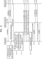
- FIG. 8 is a sequence chart of a procedure in which f1c traffic of an IAB node is transmitted to a CU of a donor node through a master node in a dual connection structure comprised of the non-donor master node and the donor secondary node, according to an embodiment of the disclosure.
- FIG. 8 illustrated is an occasion when SRB3 is used for f1c traffic transmission through an SCG path.
- an IAB node and an MN may stay connected. Furthermore, the MN may add an SN according to its decision. For example, in operation 8-04, the MN may transmit a SNAddReq message to an SN, and in operation 8-06, the MN may add the SN by receiving SNAddReqACK from the SN.
- the IAB node may receive an SCG addition configuration through RRCReconfiguration.
- the configuration information may be included in RRCReconfiguration (B) in an mrdc-SecondaryCellGroup field of an RRCReconfiguration message (A) generated by the MN.
- BAP configuration and SRB3 setup configuration information may be in the same place.
- the IAB node and the SN may perform a random access procedure.
- the IAB node may set up an SCG based on the SCG configuration information and set up SRB3. And, based on the BAP configuration information, it may establish a BAP and apply the configuration. In this case, as there is no f1c transfer path configuration information, the lAB node may recognize the default path as the SCG.
- the IAB node may add the f1c UL traffic to an NR RRC message and transmit the NR RRC message by using the SRB3 in operation 8-16.
- downstream traffic may be added to an NR RRC message and transmitted in the NR RRC message to the IAB node through SRB3, in operation 8-18.
- the f1c traffic may be sent through the MCG.
- the donor node which is an SN node
- the IAB node may change the path to the MCG based on the received configuration information in operation 8-22. Accordingly, subsequent F1-C traffic may be transmitted through the MCG.
- the lAB node may transmit the f1c traffic to the MN in an NR RRC message through the SRB1 or SRB2, and the MN separates the f1c packet from the message and transmit the f1c packet to the SN in an F1C transfer message on an Xn interface in operation 8-26.
- the SN may generate and similarly transmit an f1c packet to the MN in an F1c transfer message in operation 8-28, and the MN may transmit the f1c packet to the IAB node in an NR RRC message on the SRB1 or SRB2, in operation 8-30.
- FIG. 9 is a sequence chart of a procedure in which f1c traffic of an IAB node is transmitted to a CU of a donor node through a master node in a dual connection structure comprised of the non-donor master node and the donor secondary node, according to an embodiment of the disclosure.
- FIG. 9 illustrated is an occasion when a split SRB is used for f1c traffic transmission through an SCG path.
- an IAB node and an MN may stay connected. Furthermore, the MN may add an SN according to its decision. For example, in operation 9-04, the MN may transmit a SNAddReq message to an SN, and in operation 9-06, the MN may add the SN by receiving SNAddReqACK from the SN.
- the IAB node may receive an SCG addition configuration through RRCReconfiguration.
- the configuration information may be included in RRCReconfiguration (B) in an mrdc-SecondaryCellGroup field of an RRCReconfiguration message (A) generated by the MN.
- BAP configuration information may be in the same place.
- Split SRB1 or split SRB2 setup configuration information may be included in the RRCReconfiguration message (A).
- the MN may determine to set up a split SRB.
- the IAB node and the SN may perform a random access procedure.
- the IAB node may set up an SCG based on the SCG configuration information and set up split SRB1 or split SRB2. Furthermore, based on the BAP configuration information, the lAB node may establish a BAP and apply the configuration. In this case, as there is no f1c transfer path configuration information, the lAB node may recognize the default path as the SCG.
- the lAB node may add the f1c UL traffic to an NR RRC message and transmit the NR RRC message by using the split SRB1 or split SRB2.
- the IAB node may change the primary path for the split SRB for transmission to the SCG.
- the IAB node may change the path to the SCG only for the corresponding packet transmission and after the change, perform UL transmission in operation 9-16.
- downstream traffic may be added to an NR RRC message and transmitted in the NR RRC message to an IAB node through the split SRB, in operation 9-18.
- the IAB node continuously from the moment when the f1c transfer path is set to the SCG, the IAB node changes the primary path to the SCG and performs UL transmission on the SCG path until the donor node changes the path back to the MCG.
- PDCP PDU transmission between the MN and the SN may occur on an Xn interface.
- the f1c traffic may be transmitted through the MCG.
- the IAB node may change the primary path back to the MCG and perform UL transmission through the corresponding split SRB in the current operation.
- the donor node which is an SN node
- transmits F1-C transferPath configuration to the IAB node the IAB node may change the path to the MCG based on the received configuration information in operation 9-22. Accordingly, subsequent F1-C traffic may be transmitted through the MCG.
- the IAB node may change the primary path back to the MCG and perform UL transmission through the corresponding split SRB.
- the lAB node may transmit the f1c traffic in an NR RRC message to the MN through the split SRB in operation 9-26, and the MN separates the f1c packet from the message and transmits the f1c packet to the SN in an F1C transfer message on an Xn interface in operation 9-28.
- the SN may generate and similarly transmit an f1c packet to the MN in an F1c transfer message in operation 9-30, and the MN may transmit the f1c packet to the IAB node in an NR RRC message on the split SRB1 or split SRB2.
- FIG. 10 is a sequence chart of a procedure in which f1c traffic of an IAB node is transmitted to a CU of a donor node through a secondary node in a dual connection structure comprised of the donor master node and the non-donor secondary node, according to an embodiment of the disclosure.
- FIG. 10 illustrated is an occasion when SRB3 is used for transmission of the f1c traffic through an SCG path.
- an IAB node and an MN may stay connected.
- the IAB node may receive configuration information from the MN.
- the configuration information may be RRCReconfiguration.
- the RRCReconfiguration message may include BAP configuration information.
- the IAB node that receives the BAP configuration from the MN may set up a BAP entity and apply the configuration information thereto.
- the IAB node may set up a BH RLC channel.
- f1c and f1u traffic generated in the IAB DU may be transmitted or received to or from the CU of the MN by using the BH RCL channel.
- the MN may add an SN according to its decision. For example, in operation 10-10, the MN may determine to add an SN. Accordingly, in operation 10-12, the MN may transmit a SNAddReq message to the SN, and in operation 10-14, the MN may receive a SNAddReqACK message from the SN.
- the IAB node may receive an SCG addition configuration through RRCReconfiguration.
- the configuration information may be included in RRCReconfiguration (B) in an mrdc-SecondaryCellGroup field of an RRCReconfiguration message (A) generated by the MN.
- SRB3 setup configuration information may be in the same place.
- the IAB node may perform a random access procedure with the SN. Furthermore, the IAB node may set up an SCG based on the SCG configuration information and set up SRB3.
- the BAP configuration information is originally included in an RRCReconfiguration (A) message generated by the MN, so the default path may be the MCG.
- the IAB node may send the f1c packet on the SCG link.
- the lAB node may transmit the f1c traffic in an NR RRC message to the SN through SRB3 in operation 10-22.
- the SN may separate the f1c packet from the message and transmit the f1c packet in the F1C transfer message to the MN on the Xn interface.
- the MN may generate an f1c packet and, as described above, transmit the f1c packet in an f1c transfer message to the SN.
- the SN may transmit the f1c packet in an F1-C NR RRC message to an IAB node on SRB3.
- FIG. 11 is a sequence chart of a procedure in which f1c traffic of an IAB node is transmitted to a CU of a donor node through a secondary node in a dual connection structure comprised of the donor master node and the non-donor secondary node, according to an embodiment of the disclosure.
- a split SRB may be used for f1c traffic transmission through an SCG path.
- an IAB node and an MN may stay connected. Furthermore, in operation 11-04, the IAB node may receive configuration information from the MN.
- the configuration information may be an RRCReconfiguration message.
- the RRCReconfiguration message may include BAP configuration information.
- the IAB node that receives the BAP configuration from the MN may set up a BAP entity and apply the configuration information thereto. Furthermore, the IAB node may set up a BH RLC channel.
- f1-c and f1-u traffic generated in the IAB DU may be transmitted or received to or from the CU of the MN by using the BH RCL channel.
- the MN may add an SN according to its decision. For example, in operation 11-10, the MN may determine to add an SN. Accordingly, in operation 11-12, the MN may transmit a SNAddReq message to the SN, and in operation 11-14, the MN may receive a SNAddReqACK message from the SN.
- the IAB node may receive an SCG addition configuration through RRCReconfiguration.
- the configuration information may be included in RRCReconfiguration (B) in an mrdc-SecondaryCellGroup field of an RRCReconfiguration message (A) generated by the MN.
- Split SRB1 or split SRB2 setup configuration information may be included in the RRCReconfiguration message (A).
- the MN may determine to set up a split SRB.
- the IAB node may perform a random access procedure with the SN.
- the IAB node may set up an SCG based on the SCG configuration information.
- the IAB node may set up the split SRB1 or split SRB2.
- the BAP configuration information is originally included in an RRCReconfiguration (A) message generated by the MN, so the default path may be the MCG.
- the IAB node may send the f1c packet on the SCG link.
- the lAB node may transmit the f1c UL traffic in an NR RRC message by using the split SRB1 or split SRB2.
- the IAB node may change the primary path for the split SRB for transmission to the SCG in operation 11-22.
- the IAB node may change the path to the SCG only for the corresponding packet transmission and after the change, perform UL transmission.
- downstream traffic may be sent in an NR RRC message to the IAB node through the split SRB.
- the primary path is changed to the SCG and UL transmission may be performed on the SCG path for all the packets until the donor node changes the path back to the MCG.
- PDCP PDU transmission between the MN and the SN may occur on the Xn interface.
- the RRC message including the f1c traffic generated by the IAB node may be sent on the set path. No matter what value is set by the donor node for the f1c transfer path, it may have no effect on setting of the primary path. Hence, other upstream control messages of the IAB node are still transmitted on the currently set primary path, but the RRC message including the upstream f1c traffic may be transmitted according to the setting of the f1c transfer path.
- the IAB MT may add the f1c to an ULInformationTransfer message of LTE RRC in an octet string and transmit the message.
- E-UTRAN new radio-dual connectivity E-UTRAN new radio-dual connectivity
- the IAB MT When mobility such as handover or RRC connection reestablishment occurs before successful delivery of the ULInformationTransfer message is confirmed by a lower layer, the IAB MT needs to notify delivery failure of the ULInformationTransfer message. In this case, what entity receives which failure will now be described with reference to FIG. 12 .
- FIG. 12 is a flowchart illustrating an ULInformationTransfer failure handling procedure of an IAB node, according to an embodiment of the disclosure.
- the IAB node may determine that transmission of the ULInformationTransfer has failed. For example, when handover, an RRC connection reestablishment procedure, or the like occurs before successful transmission of the ULInformationTransfer message is confirmed by a lower layer, the IAB node may determine that the transmission of ULInformationTransfer has failed. When the transmission of ULInformationTransfer has failed, the IAB node may check whether the failed ULInformationTransfer message includes multiple dedicatedTypelnfo in operation 12-10.
- the lAB node may identify whether dedicatedInfoF1c is included in the multi-message in operation 12-15.
- the IAB MT may notify a collocated IAB DU of failure of f1c transmission, in operation 12-20.
- the IAB node may determine whether other dedicatedlnfo is included in operation 12-25. When a different type of dedicatedlnfo is included in the multi-message, the lAB node may notify a higher layer corresponding to the dedicated info type of delivery failure of the dedicated info, in operation 12-30.
- notification of the delivery failure in extra ULInformationTransfer to the higher layer or the IAB DU may not be required.
- the delivery failure of ULInformationTransfer is notified to an LTE RRC from a lower layer
- the ULInformationTransfer message includes a dedicated Info field of a type other than the f1c dedicated info
- the delivery failure may be notified to a higher layer related with the dedicated info.
- the ULInformationTransfer includes the f1c dedicated Info field, no extra delivery failure may be notified to an IAB DU or higher layer corresponding to the f1c dedicatedlnfo.
- the delivery failure may be notified to a higher layer for dedicated info of a type other than the f1c dedicated info field.
- the LTE RRC of the UE may figure out the contents and may or may not notify the transmission failure to the higher layer on a certain occasion.
- a component is represented in a singular or plural form. It should be understood, however, that the singular or plural representations are selected appropriately according to the situations presented for convenience of explanation, and the disclosure is not limited to the singular or plural form of the component. Further, the component expressed in the plural form may also imply the singular form, and vice versa.
- a computer-readable storage medium storing one or more programs (software modules) may be provided.
- the one or more programs stored in the computer-readable storage medium are configured for execution by one or more processors in an electronic device.
- the one or more programs may include instructions that cause the electronic device to perform the methods in accordance with the claims of the disclosure or the embodiments described in the specification.
- the programs may be stored in a random access memory (RAM), a non-volatile memory including a flash memory, a read only memory (ROM), an electrically erasable programmable ROM (EEPROM), a magnetic disc storage device, a compact disc-ROM (CD-ROM), a digital versatile disc (DVD) or other types of optical storage device, and/or a magnetic cassette.
- RAM random access memory
- ROM read only memory
- EEPROM electrically erasable programmable ROM
- magnetic disc storage device a compact disc-ROM (CD-ROM), a digital versatile disc (DVD) or other types of optical storage device, and/or a magnetic cassette.
- CD-ROM compact disc-ROM
- DVD digital versatile disc
- the programs may be stored in a memory including a combination of some or all of them. There may be a plurality of memories.
- the program may also be stored in an attachable storage device that may be accessed over a communication network including the Internet, an intranet, a local area network (LAN), a wide LAN (WLAN), or a storage area network (SAN), or a combination thereof.
- the storage device may be connected to an apparatus performing the embodiments of the disclosure through an external port.
- a separate storage device in the communication network may be connected to the apparatus performing the embodiments of the disclosure.
- a component is represented in a singular or plural form. It should be understood, however, that the singular or plural representations are selected appropriately according to the situations presented for convenience of explanation, and the disclosure is not limited to the singular or plural form of the component. Further, the component expressed in the plural form may also imply the singular form, and vice versa.
Landscapes
- Engineering & Computer Science (AREA)
- Signal Processing (AREA)
- Computer Networks & Wireless Communication (AREA)
- Mobile Radio Communication Systems (AREA)
Applications Claiming Priority (4)
| Application Number | Priority Date | Filing Date | Title |
|---|---|---|---|
| KR20200186776 | 2020-12-29 | ||
| KR20210005388 | 2021-01-14 | ||
| KR1020210029663A KR20220095060A (ko) | 2020-12-29 | 2021-03-05 | 백홀 및 액세스 홀 결합 시스템에서 제어 평면 시그날링을 지원하는 장치 및 방법 |
| PCT/KR2021/020207 WO2022146044A1 (fr) | 2020-12-29 | 2021-12-29 | Dispositif et procédé de prise en charge de signalisation de plan de commande dans un système d'accès et liaison terrestre intégrés |
Publications (2)
| Publication Number | Publication Date |
|---|---|
| EP4258802A1 true EP4258802A1 (fr) | 2023-10-11 |
| EP4258802A4 EP4258802A4 (fr) | 2024-06-12 |
Family
ID=82259537
Family Applications (1)
| Application Number | Title | Priority Date | Filing Date |
|---|---|---|---|
| EP21915841.7A Pending EP4258802A4 (fr) | 2020-12-29 | 2021-12-29 | Dispositif et procédé de prise en charge de signalisation de plan de commande dans un système d'accès et liaison terrestre intégrés |
Country Status (3)
| Country | Link |
|---|---|
| US (1) | US20240064850A1 (fr) |
| EP (1) | EP4258802A4 (fr) |
| WO (1) | WO2022146044A1 (fr) |
Family Cites Families (15)
| Publication number | Priority date | Publication date | Assignee | Title |
|---|---|---|---|---|
| CN110351810B (zh) * | 2018-04-04 | 2022-01-14 | 大唐移动通信设备有限公司 | 一种接入方法和设备 |
| CN112042259B (zh) * | 2018-05-10 | 2024-03-08 | 三星电子株式会社 | 用于在无线通信系统中执行通信的方法和装置 |
| CN110430599B (zh) * | 2018-09-28 | 2020-10-16 | 华为技术有限公司 | 数据传输的方法和装置 |
| WO2020154622A1 (fr) * | 2019-01-24 | 2020-07-30 | Apple Inc. | Système et procédé de fonctionnement d'un équipement utilisateur (ue) de communication de type machine améliorée (emtc) et d'équipements utilisateur (ue) sur l'internet des objets à bande étroite (nb-iot) lorsqu'ils sont connectés à un réseau central 5g (5gcn) |
| WO2020167657A1 (fr) * | 2019-02-13 | 2020-08-20 | Apple Inc. | Transmission, retransmission, et processus de demande de répétition automatique hybride à l'aide de ressources de liaison montante préconfigurées dans un mode inactif |
| CN111586887B (zh) * | 2019-02-15 | 2023-03-28 | 华为技术有限公司 | 无线回传系统、通信方法及其装置 |
| CN113906817A (zh) * | 2019-03-26 | 2022-01-07 | 苹果公司 | 中继节点中的链路建立 |
| CN114467288A (zh) * | 2019-09-30 | 2022-05-10 | 华为技术有限公司 | 一种数据包传输方法及装置 |
| EP4055986A1 (fr) * | 2019-11-08 | 2022-09-14 | Telefonaktiebolaget LM Ericsson (publ) | Attribution de trajet par défaut dans des réseaux iab |
| US11963243B2 (en) * | 2020-04-08 | 2024-04-16 | Qualcomm Incorporated | Establishing a signaling connection in a wireless network |
| WO2021211048A1 (fr) * | 2020-04-17 | 2021-10-21 | Telefonaktiebolaget Lm Ericsson (Publ) | Premier nœud, second nœud et procédés exécutés par ceux-ci permettant de gérer des transmission dans un réseau de communications |
| EP4186323A1 (fr) * | 2020-07-22 | 2023-05-31 | Telefonaktiebolaget LM Ericsson (publ) | Noeud de réseau radio, équipement utilisateur et procédés exécutés dans un réseau de communication sans fil |
| KR20230029783A (ko) * | 2020-07-30 | 2023-03-03 | 지티이 코포레이션 | 통합 액세스 및 백홀 네트워크에서의 구성 정보 교환 |
| CN116671246A (zh) * | 2020-10-22 | 2023-08-29 | 谷歌有限责任公司 | 管理集成接入和回程移动性 |
| KR20220095060A (ko) * | 2020-12-29 | 2022-07-06 | 삼성전자주식회사 | 백홀 및 액세스 홀 결합 시스템에서 제어 평면 시그날링을 지원하는 장치 및 방법 |
-
2021
- 2021-12-29 EP EP21915841.7A patent/EP4258802A4/fr active Pending
- 2021-12-29 WO PCT/KR2021/020207 patent/WO2022146044A1/fr not_active Ceased
- 2021-12-29 US US18/259,474 patent/US20240064850A1/en active Pending
Also Published As
| Publication number | Publication date |
|---|---|
| US20240064850A1 (en) | 2024-02-22 |
| WO2022146044A1 (fr) | 2022-07-07 |
| EP4258802A4 (fr) | 2024-06-12 |
Similar Documents
| Publication | Publication Date | Title |
|---|---|---|
| CN113748618B (zh) | 用于在无线通信系统中通过使用多个波束发送和接收信号的方法和装置 | |
| US11553558B2 (en) | Method and apparatus for accelerating ciphering and deciphering in wireless communication system | |
| US20230066714A1 (en) | Method and apparatus for resource management for conditional handover in wireless communication system | |
| US12096406B2 (en) | Method and apparatus for uplink transmission using MIMO in wireless communication system | |
| EP4304246A1 (fr) | Procédé de fonctionnement pour coexistence de mobilité conditionnelle dans un système de communication mobile de prochaine génération | |
| US12047348B2 (en) | Method and device for allocating IP address to DU in integrated access and backhaul system | |
| CN113261332B (zh) | 用于在无线通信系统中发送或接收数据的方法和装置 | |
| KR20230053428A (ko) | 마스터 노드의 세컨더리 셀 의 조건부 이동을 위한 방법 | |
| CN113647146B (zh) | 用于下一代移动通信系统中的切换方法和装置 | |
| CN114503672A (zh) | 用于条件切换的测量方法和设备 | |
| KR20210095389A (ko) | 무선 이동통신에서 랜덤 액세스 보고를 위한 갱신 방법 | |
| KR20220017863A (ko) | 무선 통신 시스템에서 결합 액세스 및 백홀 시스템을 위한 개선된 셀 선택 및 실패 처리 방법 및 장치 | |
| KR20230008501A (ko) | 이동통신 시스템에서 동시에 여러 개의 캐리어에 대한 pdcch 수신 빔을 활성화하는 방법 및 장치 | |
| KR20230000769A (ko) | 무선 통신 시스템에서 지역 재-라우팅을 수행하기 위한 장치 및 방법 | |
| KR20220113025A (ko) | 무선 통신 시스템에서 스케줄링을 수행하기 위한 방법 및 장치 | |
| US12494867B2 (en) | Method and apparatus for performing PDCCH repetitive transmission through plurality of transmission and reception points (TRPS) in next-generation mobile communication system | |
| EP4415438A1 (fr) | Procédé et dispositif de préréglage de données d'assistance pour la localisation d'un terminal dans un système de communication sans fil | |
| CN119586223A (zh) | 下一代无线通信系统中用于网络控制中继器的初始接入的装置和方法 | |
| KR20230105183A (ko) | 백 홀 및 액세스 홀 결합 시스템에서, 도너 노드간 통신시의 연결 실패의 처리 장치 및 방법 | |
| KR20230012356A (ko) | 백홀 액세스 홀 결합 시스템에서 도너 간 이동성 수행시 선택적 admission 제어 방법 | |
| KR20220095060A (ko) | 백홀 및 액세스 홀 결합 시스템에서 제어 평면 시그날링을 지원하는 장치 및 방법 | |
| KR20220136875A (ko) | 비활성 모드 및 대기 모드에서 포지셔닝을 위한 측정 결과를 전송하는 방법 및 장치 | |
| EP4258802A1 (fr) | Dispositif et procédé de prise en charge de signalisation de plan de commande dans un système d'accès et liaison terrestre intégrés | |
| KR20210039868A (ko) | 백홀 및 액세스 홀 통합 시스템을 위한 신호 무선 베어러 설정 방법 및 장치 | |
| KR102863034B1 (ko) | 조건부 핸드오버를 위한 측정 방법 및 장치 |
Legal Events
| Date | Code | Title | Description |
|---|---|---|---|
| STAA | Information on the status of an ep patent application or granted ep patent |
Free format text: STATUS: THE INTERNATIONAL PUBLICATION HAS BEEN MADE |
|
| PUAI | Public reference made under article 153(3) epc to a published international application that has entered the european phase |
Free format text: ORIGINAL CODE: 0009012 |
|
| STAA | Information on the status of an ep patent application or granted ep patent |
Free format text: STATUS: REQUEST FOR EXAMINATION WAS MADE |
|
| 17P | Request for examination filed |
Effective date: 20230704 |
|
| AK | Designated contracting states |
Kind code of ref document: A1 Designated state(s): AL AT BE BG CH CY CZ DE DK EE ES FI FR GB GR HR HU IE IS IT LI LT LU LV MC MK MT NL NO PL PT RO RS SE SI SK SM TR |
|
| DAV | Request for validation of the european patent (deleted) | ||
| DAX | Request for extension of the european patent (deleted) | ||
| A4 | Supplementary search report drawn up and despatched |
Effective date: 20240515 |
|
| RIC1 | Information provided on ipc code assigned before grant |
Ipc: H04W 88/08 20090101ALN20240508BHEP Ipc: H04W 84/04 20090101ALN20240508BHEP Ipc: H04L 5/00 20060101ALI20240508BHEP Ipc: H04W 72/12 20090101ALI20240508BHEP Ipc: H04W 28/02 20090101ALI20240508BHEP Ipc: H04W 40/22 20090101ALI20240508BHEP Ipc: H04W 76/19 20180101ALI20240508BHEP Ipc: H04W 76/15 20180101AFI20240508BHEP |