EP4260424B1 - Alimentation électrique dc à tension double - Google Patents
Alimentation électrique dc à tension double Download PDFInfo
- Publication number
- EP4260424B1 EP4260424B1 EP21843918.0A EP21843918A EP4260424B1 EP 4260424 B1 EP4260424 B1 EP 4260424B1 EP 21843918 A EP21843918 A EP 21843918A EP 4260424 B1 EP4260424 B1 EP 4260424B1
- Authority
- EP
- European Patent Office
- Prior art keywords
- power
- voltage
- converter
- error condition
- power supply
- Prior art date
- Legal status (The legal status is an assumption and is not a legal conclusion. Google has not performed a legal analysis and makes no representation as to the accuracy of the status listed.)
- Active
Links
Images


Classifications
-
- H—ELECTRICITY
- H02—GENERATION; CONVERSION OR DISTRIBUTION OF ELECTRIC POWER
- H02J—ELECTRIC POWER NETWORKS; CIRCUIT ARRANGEMENTS OR SYSTEMS FOR SUPPLYING OR DISTRIBUTING ELECTRIC POWER; SYSTEMS FOR STORING ELECTRIC ENERGY
- H02J1/00—Circuit arrangements for DC mains or DC distribution networks
- H02J1/08—Three-wire DC power distribution systems; Systems having more than three wires
- H02J1/082—DC supplies with two or more different DC voltage levels
-
- H—ELECTRICITY
- H02—GENERATION; CONVERSION OR DISTRIBUTION OF ELECTRIC POWER
- H02J—ELECTRIC POWER NETWORKS; CIRCUIT ARRANGEMENTS OR SYSTEMS FOR SUPPLYING OR DISTRIBUTING ELECTRIC POWER; SYSTEMS FOR STORING ELECTRIC ENERGY
- H02J1/00—Circuit arrangements for DC mains or DC distribution networks
- H02J1/002—Circuit arrangements for DC mains or DC distribution networks using intermediate DC-AC-DC conversion
-
- H—ELECTRICITY
- H02—GENERATION; CONVERSION OR DISTRIBUTION OF ELECTRIC POWER
- H02J—ELECTRIC POWER NETWORKS; CIRCUIT ARRANGEMENTS OR SYSTEMS FOR SUPPLYING OR DISTRIBUTING ELECTRIC POWER; SYSTEMS FOR STORING ELECTRIC ENERGY
- H02J1/00—Circuit arrangements for DC mains or DC distribution networks
- H02J1/10—Parallel operation of DC sources
- H02J1/12—Parallel operation of DC sources having power converters with further DC sources without power converters
-
- H—ELECTRICITY
- H02—GENERATION; CONVERSION OR DISTRIBUTION OF ELECTRIC POWER
- H02J—ELECTRIC POWER NETWORKS; CIRCUIT ARRANGEMENTS OR SYSTEMS FOR SUPPLYING OR DISTRIBUTING ELECTRIC POWER; SYSTEMS FOR STORING ELECTRIC ENERGY
- H02J9/00—Circuit arrangements for emergency or stand-by power supply, e.g. for emergency lighting
- H02J9/04—Circuit arrangements for emergency or stand-by power supply, e.g. for emergency lighting in which the distribution system is disconnected from the normal source and connected to a standby source
- H02J9/06—Circuit arrangements for emergency or stand-by power supply, e.g. for emergency lighting in which the distribution system is disconnected from the normal source and connected to a standby source with automatic change-over, e.g. UPS systems
- H02J9/061—Circuit arrangements for emergency or stand-by power supply, e.g. for emergency lighting in which the distribution system is disconnected from the normal source and connected to a standby source with automatic change-over, e.g. UPS systems for DC powered loads
-
- B—PERFORMING OPERATIONS; TRANSPORTING
- B64—AIRCRAFT; AVIATION; COSMONAUTICS
- B64D—EQUIPMENT FOR FITTING IN OR TO AIRCRAFT; FLIGHT SUITS; PARACHUTES; ARRANGEMENT OR MOUNTING OF POWER PLANTS OR PROPULSION TRANSMISSIONS IN AIRCRAFT
- B64D2221/00—Electric power distribution systems onboard aircraft
-
- H—ELECTRICITY
- H02—GENERATION; CONVERSION OR DISTRIBUTION OF ELECTRIC POWER
- H02J—ELECTRIC POWER NETWORKS; CIRCUIT ARRANGEMENTS OR SYSTEMS FOR SUPPLYING OR DISTRIBUTING ELECTRIC POWER; SYSTEMS FOR STORING ELECTRIC ENERGY
- H02J2105/00—Networks for supplying or distributing electric power characterised by their spatial reach or by the load
- H02J2105/30—Networks for supplying or distributing electric power characterised by their spatial reach or by the load the load networks being external to vehicles, i.e. exchanging power with vehicles
- H02J2105/32—Networks for supplying or distributing electric power characterised by their spatial reach or by the load the load networks being external to vehicles, i.e. exchanging power with vehicles for aircrafts
Definitions
- the present technology relates to a power supply providing DC power at two distinct voltages.
- the European Aviation Safety Agency has defined a certification specification CS-23 applicable to small, single engine aircraft. These aircraft generally include two separate DC electrical systems.
- One electrical system is a low-voltage electrical system providing power to a low-voltage load including an engine management system (EMS) for controlling the aircraft engine.
- Another electrical system is a high-voltage electrical system providing power to a high-voltage load including various aircraft electrical systems within the aircraft, for example for lighting and ventilation apparatuses, landing gear motor, and the like.
- the low-voltage electrical system may for example have a 12V nominal voltage and the high-voltage electrical system may for example have a 24V nominal voltage.
- the two distinct AC power generators are driven by the aircraft engine. Distinct AC/DC converters are fed AC power from the AC power generators; one AC/DC converter provides DC power to the high-voltage load while the other AC/DC converter provides DC power to the low-voltage load. Should one of the AC power generators fail, delivery of power at the low voltage to the EMS is prioritized for safety reasons and delivery of power to the high-voltage load may cease.
- US 5864221 discloses a standby power supply dedicated to a peripheral electronics apparatus on aircraft providing an isolated ungrounded self-contained source of DC operating voltage. That source is applied to the electronics apparatus upon indication of turbine generator shut-down or failure before the voltage generated by the turbine generator completely falls off. Formed with an EMI filter, a fast pulse mode battery charger, a lead-acid battery pack, a DC to DC converter, and a pair of electromagnetic relays, the standby power supply ensures that the electronic apparatus is never without operating power even momentarily.
- CN 106208256 discloses an airborne electronic terminal charging module for connection with an electronic terminal on an aviation aircraft.
- the airborne electronic terminal charging module comprises an input protection unit, a voltage conversion unit, an output protection unit, a first output interface unit, a communication unit and a processor.
- An airborne power supply is converted into a stable power supply suitable for the electronic terminal and supplies to the electronic terminal through the input protection unit, the voltage conversion unit, the output protection unit and the first output interface unit.
- Output current value information is detected through the output protection unit in real time; and the processor controls the output protection unit to connect or disconnect electric power output according to the current value information, transmits working state information of the airborne electronic terminal charging module to an upper computer or receives a control instruction from the upper computer.
- the protection circuit is further adapted for preventing transfer of the DC power from the first DC/DC converter to the high-voltage load in response to an error condition selected from an undervoltage of the DC power source, an overvoltage at an output of the first DC/DC converter, an overcurrent in the protection circuit, a high-temperature condition, and a combination thereof.
- the power supply further comprises a monitoring circuit operatively connected to the protection circuit, the monitoring circuit being configured for outputting a high-voltage power unavailable indication in response to the error condition.
- the monitoring circuit is further operatively connected to the second DC/DC converter; and the monitoring circuit is further configured for detecting that the DC power at the low voltage is unavailable and, in response thereto, outputting a low-voltage power unavailable indication.
- the power supply further comprises a start and backup input circuit adapted for receiving DC power from a backup source; and wherein: the second DC/DC converter is further adapted for converting DC power received from the backup source via the start and backup input circuit to DC power at the low voltage; and the protection circuit is further adapted for receiving DC power from the backup source via the start and backup input circuit and for selectively delivering the DC power from the backup source to the high-voltage load.
- the power supply further comprises a monitoring circuit operatively connected to the start and backup input circuit, the monitoring circuit being adapted for outputting a backup power indication in response DC power being received from the backup source.
- the start and backup input circuit comprises a diode adapted for preventing a return of DC power from the first DC/DC converter to the backup source.
- the protection circuit comprises one or more sensors selected from: a temperature sensor adapted for measuring a temperature of the power supply, a first voltage sensor adapted for measuring a voltage provided by the DC power source, a second voltage sensor adapted for measuring a voltage provided by the first DC/DC converter, and a current sensor adapted for measuring a current output by the protection circuit; and the protection circuit further comprises: a switch adapted for selectively transferring the DC power from the first DC/DC converter to the high-voltage load, and a switch controller, operatively connected to the one or more sensors, the switch controller being adapted for declaring an error condition based on one or more signals from the one or more sensors and for causing opening of the switch in response to declaring the error condition; wherein the error condition is selected from: a temperature error condition declared in response to the temperature of the power supply exceeding a high-temperature threshold, an overvoltage error condition declared in response to the voltage provided by the first DC/DC converter exceeding an overvoltage threshold, an undervoltage error condition declared
- the protection circuit comprises an internal timer adapted for selectively resetting the error condition at a predetermined time after occurrence of the error condition.
- the protection circuit in response to the error condition being the undervoltage error condition, resets the undervoltage error condition in response to the voltage provided by the DC power source being greater than or equal to an undervoltage reset threshold greater than the undervoltage threshold at the predetermined time after the occurrence of the error condition.
- the monitoring circuits in response to the error condition being the temperature error condition, resets the temperature error condition in response to the temperature of the power supply being less than or equal to a temperature reset threshold lower than the high-temperature threshold at the predetermined time after the occurrence of the error condition.
- the second DC/DC converter comprises a galvanic isolation.
- the second DC/DC converter comprises: an internal DC/AC converter adapted for receiving the DC power from the first DC/DC converter and for converting the received DC power to high-frequency AC power; an internal AC/DC converter adapted for converting the high-frequency AC power to the DC power at the low voltage and for delivering the DC power at the low voltage to the low-voltage load; and an internal transformer adapted for transferring the AC power from the internal DC/AC convertor to the internal AC/DC converter.
- the internal DC/AC converter comprises an inverter operating at a frequency in a range between 100 and 200 KHz.
- each of the first and second DC/DC converters is a switching regulator.
- the DC power source is a main AC/DC converter internal to the power supply, the main AC/DC converter having an input adapted for receiving AC power from an external power source and an output adapted for delivering the DC power at the variable bulk voltage to the first DC/DC converter.
- the main AC/DC converter is a bridge rectifier adapted for receiving a multiphase AC power from the external power source.
- the AC power is received from the external power source at a variable voltage.
- the main AC/DC converter is adapted for receiving the AC power from a generator driven by an aircraft engine.
- the second DC/DC converter is adapted for providing power to an engine management system of the aircraft engine, the engine management system being part of the low-voltage load; and the first DC/DC converter is adapted for providing power aircraft electrical systems being part of the high-voltage load.
- the low voltage has a 12-volt nominal value; and the high voltage has a 24-volt nominal value.
- Embodiments of the present technology each have at least one of the above-mentioned objects and/or aspects, but do not necessarily have all of them. It should be understood that some aspects of the present technology that have resulted from attempting to attain the above-mentioned object may not satisfy this object and/or may satisfy other objects not specifically recited herein.
- the present technology will be described with respect to an electrical power system implemented in a CS-23 type light aircraft having a single gas-fueled piston engine and a pair of AC generators driven by the piston engine.
- the present technology could be applied to other aircraft, for example twin-engine aircraft.
- Application of the present technology is therefore not intended to be limited to its use in CS-23 aircraft.
- an intended use of the present technology is to control delivery of DC power to various components of an aircraft, the present technology can also be used for other applications that benefit from dual-voltage DC power delivery.
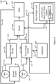
- FIG. 1 A block diagram of an electrical power system 100 of a CS-23 type aircraft in accordance with one embodiment of the present technology is shown in Figure 1 .
- the electrical power system 100 of the aircraft comprises two complementary AC generators 110 (Gen A) and 120 (Gen B) driven by an aircraft engine 50.
- the AC generators 110 and 120 output multiphase AC power, for example tri-phase AC power. Voltages at the outputs of the AC generators 110 and 120 may vary greatly according to a rotational speed of the aircraft engine 50.
- AC power from the AC generator 110 is applied to a power input 115 of single-voltage AC/DC converter 130 having a power output 135 providing DC power at a low nominal voltage.
- This low nominal voltage is generally referred to as 12V, but is usually closer to about 14V in normal operation.
- DC power from the single-voltage AC/DC converter 130 is applied to a switch 140 controlled by a control and back-up power system 150.
- the switch 140 allows transferring the DC power from the single-voltage AC/DC converter 130 to an electronic management system (EMS) 160 that controls 165 the aircraft engine 50.
- the EMS 160 may include an electronic control unit (ECU), a fuel pump, electronic injectors and electronic ignition (all of which are not shown) for operating the aircraft engine 50.
- the switch 140 may comprise a plurality of fuses for individually directing parts of DC power to the various components of the EMS 160.
- AC power from the AC generator 120 is applied to a power input 125 of a dual-voltage AC/DC converter 200 having a power output 142 providing DC power at the low nominal voltage and another power output 172 providing DC power at a high nominal voltage.
- This high nominal voltage is generally referred to as 24V, but is usually closer to about 28V in normal operation.
- DC power at the low nominal voltage from the dual-voltage AC/DC converter 200 is applied to the switch 140.
- the switch 140 When DC power is available from the single-voltage AC/DC converter 130, the switch 140 usually prevents transferring the DC power from the dual-voltage AC/DC converter 200 to the EMS 160.
- the DC power at the high nominal voltage is provided by the dual-voltage AC/DC converter 200 to a high-voltage load 170 that may include a variety of electrical systems of the aircraft such as, for example and without limitation, ventilation and lighting equipment (not shown).
- the control and back-up power system 150 is part of the high-voltage load 170.
- the control and back-up power system 150 comprises an internal battery 155 having a 24V nominal voltage.
- the internal battery 155 is connected at a power input 157 to the dual-voltage AC/DC converter 200.
- a group of indicators 180 for example an instrument cluster and/or a group of warning light, is connected to a signalling output 185 of the dual-voltage AC/DC converter 200.
- the control and back-up power system 150 causes 24V DC power to be delivered from the internal battery 155 to the dual-voltage AC/DC converter 200 at the power input 157 and, concurrently, causes the switch 140 to allow transferring 14V DC power from the dual-voltage AC/DC converter 200 to the EMS 160.
- the ECU causes starting of the aircraft engine 50, for example by causing a starter (not shown) powered by the internal battery 155 of the control and back-up power system 150 or by an external battery (not shown) to start the aircraft engine 50.
- the AC generators 110 and 120 When the aircraft engine 50 is idling, the AC generators 110 and 120 generate an AC power at a sufficient AC voltage for both the single-voltage AC/DC converter 130 and the dual-voltage AC/DC converter 200 to output DC power at or above the low nominal voltage, generally at 14V.
- the EMS 160 may measure the voltages at the power output 135 of the single-voltage AC/DC converter 130 and at the power output 142 of the dual-voltage AC/DC converter 200 and act upon the switch 140 to cause 14V DC power be delivered from the single-voltage AC/DC converter 130 to the EMS 160.
- the voltage provided by the AC generator 120 to the dual-voltage AC/DC converter 200 may not be sufficient for the dual-voltage AC/DC converter 200 to produce DC power at the high nominal voltage.
- the dual-voltage AC/DC converter 200 may still be connected to internal battery 155 to receive 24V at its power input 157 and output DC power at 24V to power the high-voltage load 170.
- the voltage provided by the AC generator 120 to the dual-voltage AC/DC converter 200 is more than sufficient for the dual-voltage AC/DC converter 200 to produce DC power at the high nominal voltage and to provide DC power from the power output 172 to the high-voltage load 170.
- the dual-voltage AC/DC converter 200 no longer needs to receive DC power from the internal battery 155 at its power input 157.
- a portion of the DC power provided to the high-voltage load 170 may be used to recharge the internal battery 155.
- control and back-up power system 150 may cause the switch 140 to allow transferring 14V DC power from the power output 142 of the dual-voltage AC/DC converter 200 to the EMS 160. Should the aircraft engine 50 stall, the control and back-up power system 150 may optionally cause the dual-voltage AC/DC converter 200 to transfer 24V DC power from the internal battery 155 to the high-voltage load 170.
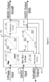
- FIG 2 is a block diagram of an embodiment of the dual-voltage AC/DC converter 200.
- the dual-voltage AC/DC converter 200 includes two power inputs 125, 157, two power outputs 172, 142 and an indication output 185.
- the power input 125 receives AC power, for example tri-phase or multiphase AC power, from the AC generator (Gen B) 120 of Figure 1 .
- the AC power is applied to a rectifier 210 that acts as a main AC/DC converter that converts the AC power to DC power 212 at a variable bulk voltage.
- the rectifier 210 may be understood as a DC power source providing DC power at a variable bulk voltage to a first DC/DC converter 220.
- An instantaneous value of the bulk voltage is about equal to a peak voltage of the AC power applied to the rectifier 210, although a slight voltage drop may take place in components of the rectifier 210.
- the bulk voltage may be, for example and without limitation, in a range between 16 and 170 V DC.
- the bulk voltage is applied to a first DC/DC converter 220, which is capable of converting the DC power 212 at the variable bulk voltage to DC power present at an output 222.
- the DC power at the output 222 is at the high nominal voltage (nominally 24V, but generally up to about 28V in operation) for powering the high-voltage load 170.
- the first DC/DC converter 220 may for example be a switching converter. DC power from the first DC/DC converter 220 may or may not be directed to the high-voltage load 170, depending on the state of a protection circuit 230 electrically connected between the first DC/DC converter 220 and the power output 172.
- the protection circuit 230 allows delivery of power from the power output 172 of the first DC/DC converter 220 to the high-voltage load 170.
- the protection circuit 230 may prevent delivery of power from the first DC/DC converter 220 to the high-voltage load 170 in the presence of an error condition.
- protection circuit 230 may detect one or more error conditions, which are described in detail below. Detection of an error condition may cause the protection circuit 230 to stop delivery of power from the first DC/DC converter 220 to the high-voltage load 170.
- the output 222 of the first DC/DC converter 220 is also connected to an input of a second DC/DC converter 240.
- the second DC/DC converter 240 converts the voltage provided by the first DC/DC converter 220 to the low nominal voltage (nominally 12V, but generally up to about 14 V in operation).
- the voltage at the output 222 of the first DC/DC converter 220 is sufficient for the second DC/DC converter 240 to provide the low nominal voltage at the power output 142 for powering the EMS 160 ( Figure 1 ).
- the double oblique lines shown in the illustration of the second DC/DC converter 240 indicate that this converter is galvanically isolated, in an embodiment, to fully isolate the power output 142 from any high-voltage component of the electrical power system 100.
- the power input 157 of the dual-voltage AC/DC converter 200 is selectively connected to the internal battery 155 of the control and back-up power system 150 ( Figure 1 ). It may be always connected to the internal battery 155, or may alternatively be connected as directed by the control and back-up power system 150.
- a start and backup input circuit 250 selectively connects the power input 157 to the protection circuit 230 and to the second DC/DC converter 240 to deliver backup DC power 252 at 24V.
- 24V DC power from the internal battery 155 present at the power input 157 may be applied to the second DC/DC converter 240 to generate the 14V power for powering the EMS 160.
- the protection circuit 230 may emit an error signal 239 causing a monitoring circuit 260 to emit an indication on the indication output 185 for showing statuses and/or warnings on the group of indicators 180.
- the monitoring circuit 250 may also detect the presence of backup DC power 252 at the output of the start and backup input circuit 250 and emit another indication on the indication output 185 for showing statuses and/or warnings on the group of indicators 180.
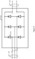
- FIG 3 is a simplified block diagram of the rectifier 210.
- the power input 125 may be a multiphase power input, for example and without limitation a tri-phase power input.
- the output 212 of the rectifier 210 comprises positive and negative connections.
- the rectifier 210 in the example of Figure 3 is a bridge rectifier comprising six diodes 214, which may be, for example and without limitation MBRB40250TG Switch-mode power rectifier Schottky diodes from ON Semiconductor TM or any suitable equivalent diode.
- a pair of diodes being used to convert the AC voltage from each of three phases of the AC power received at the input 125 into DC power at a bulk voltage at the output 212.
- the bulk voltage present at the output 212 is substantially equivalent to the peak of the AC voltage at the power input 125, although a slight voltage drop may occur as current flows through the diodes 214.
- the rectifier 210 may include more components, for example and without limitation one of more capacitors (not shown) used to minimize variations of the bulk voltage at the output 212.
- FIG 4 is a simplified block diagram of the first DC/DC converter 220. Although illustrated as single lines on Figure 2 , the output 212 of the rectifier 210 and the output 222 of the first DC/DC converter 220 each comprises positive and negative connections.
- the first DC/DC converter 220 comprises a switch 221, a shunt resistor 226, a controlling integrated circuit 223 and a voltage filter including an inductance 224 and a capacitance 225.
- the switch 221 may be implemented as a of MOSFET transistor (not shown).
- the controlling integrated circuit 223 may be a UCC28C43 current mode Pulse Width Modulation (PWM) controller from Texas Instruments TM , or any suitable equivalent thereof.
- PWM Pulse Width Modulation
- the controlling integrated circuit 223 senses a DC voltage across the shunt resistor 226. If the sensed DC voltage is less than or equal to a reference, the controlling integrated circuit 223 causes closing of the switch 221 so that the bulk voltage present at the output 212 of the rectifier 210 is applied to the voltage filter including the inductance 224 and the capacitance 225 to produce a DC voltage at the output 222 of the first DC/DC converter 220 that is substantially equal to the bulk voltage. If the sensed voltage is greater than the reference, the controlling integrated circuit 223 may selectively cause rapid opening and closing of the switch 221 so that the DC voltage at the output 222 remains close to the operating voltage of 28V. In an embodiment, the switch 221 may be opened and closed at a rate of up to 200 KHz. A diode 228 (or another MOSFET transistor polarized to operate as the diode 228) may be used to complete the circuit of Figure 4 when the switch 221 is open.
- the first DC/DC converter 220 its output 222 is expected to be substantially equal to the variable bulk voltage at the output 212 of the rectifier when the switch 221 is maintained in a closed (conducting) condition for any extended time period, for example when the bulk voltage is less than the high nominal voltage.
- FIG 5 is a block diagram of the protection circuit 230.
- the protection circuit 230 receives the DC power from the output 222 of the first DC/DC converter 220 and, in normal operating conditions, transmits the DC power to the high-voltage load 170 ( Figure 1 ) via the power output 172.
- a switch 231 which may for example comprise a MOSFET transistor, is closed and conducting in normal operation.
- the protection circuit 230 may detect a number of error conditions that may be reported to a switch controller 232 that may cause opening of the switch 231.
- One error condition may be an undervoltage condition detected when a voltage sensor 233 electrically connected to the output 212 of the rectifier 210 detects that the bulk voltage is lower than a predetermined threshold, for example 37.2V.
- a predetermined threshold for example 37.2V.
- the first DC/DC converter 220 may be able to produce some DC power at least at the nominal voltage of 24V, but may not be able to provide sufficient DC power to fulfill the needs of the high-voltage load 170.
- Another error condition may be an overvoltage condition detected when another voltage sensor 234 detects that the output voltage of the first DC/DC converter 220 exceeds a predetermined threshold, for example 32.75V.
- a further error condition may be an overcurrent condition.
- a shunt resistor 235 having a low impedance, for example 1.5 milli-ohm, is mounted in series with the switch 231.
- a voltage sensor 236 measures the voltage across the shunt resistor 235, this voltage reflecting the current at the output 172.
- the overcurrent condition is detected when the current at the output 172 is greater than a predetermined threshold, for example 30.7 amperes.
- Yet another error condition may be a high-temperature condition detected when a temperature sensor 237 detects that a temperature of the dual-voltage AC/DC converter 200 exceeds a predetermined threshold.
- the temperature sensor 237 may detect a temperature of MOSFETs forming the switch 221 of the first DC/DC converter, the threshold being for example 145°C.
- the switch controller 232 When one or more of the above-mentioned error conditions is reported to the switch controller 232, the switch controller 232 causes an opening of the switch 231. As a result, delivery of DC power from the first DC/DC converter 220 to the high-voltage load 170 is stopped.
- the switch controller 232 may include an internal timer 238. In this embodiment, the switch controller 232 may cause the switch 231 to close again after a predetermined time period, for example after 3 or 4 seconds, following the detection of the error condition. If the error condition having caused the opening of the switch 231 is no longer present, the switch 231 may remain closed and power delivery to the high-voltage load 170 may resume.
- the switch controller 232 may implement a temperature hysteresis to maintain the high-temperature condition, once detected, until the temperature sensor 237 reports that the temperature has fallen below another, lower temperature threshold, for example 115°C. Still in the same or another embodiment, the switch controller 232 may implement a bulk voltage hysteresis to maintain the effect of the undervoltage condition unless the bulk voltage now exceeds another, higher predetermined threshold, for example 44.7V.
- FIG. 6 is a block diagram of the second DC/DC converter 240.
- the second DC/DC converter 240 comprises several elements that are similar to those found in the first DC/DC converter 220. These elements include, for example, a switch 241, a shunt resistor 246, a controlling integrated circuit 243, an inductance 244, a capacitance 245 and a diode 248 that operate substantially in the same manner as do the switch 221, the shunt resistor 226, the controlling integrated circuit 223, the inductance 224, the capacitance 225 and the diode 228 of the first DC/DC converter 220.
- a switch 241 a shunt resistor 246, a controlling integrated circuit 243, an inductance 244, a capacitance 245 and a diode 248 that operate substantially in the same manner as do the switch 221, the shunt resistor 226, the controlling integrated circuit 223, the inductance 224, the capacitance 225 and the diode 228 of the first DC/DC converter 2
- the power output 142 of second DC/DC converter 240 is galvanically isolated from the first DC/DC converter 220 and from any high-voltage component of the electrical power system 100 of the aircraft in order to further protect the EMS 160 from eventual electrical faults occurring in the high-voltage load 170.
- the DC power received at the second DC/DC converter 240 from the output 222 of the first DC/DC converter, or the DC power 252 received from the start and backup input circuit 250 is fed to a high-frequency inverter 242 that converts the DC power to AC power.
- the high-frequency inverter 242 may operate in a frequency range, for example between 100 and 200 KHz, being controlled by an inverter controller 243A, for example a LM5045 Full-bridge PWM controller from Texas Instruments TM or any suitable equivalent thereof, the inverter controller 243A being itself controlled by the controlling integrated circuit 243.
- the AC power generated by the inverter 242 is applied to the primary side of a transformer 247.
- AC power at the secondary side of the transformer 247 is applied to a rectifier 249 that converts the AC power to DC power while preserving the galvanic isolation between the output of the rectifier 249 and the input of the second DC/DC converter 240.
- Figure 6 shows that the switch 241 is positioned on the secondary side of the transformer 247, positioning the switch 241 on the primary side of the transformer 247, either before or after the inverter 242, is also contemplated.
- the controlling integrated circuit 243 senses a DC voltage across the shunt resistor 246.
- the controlling integrated circuit 243 may cause a rapid opening and closing of the switch 241 and may also control the operation of the inverter 242 so that the DC voltage at the output 142 remains close to the operating voltage of 14V.
- FIG. 7 is a block diagram of the start and backup input circuit 250.
- the start and backup input circuit 250 may comprise a single diode 255, for example and without limitation a MBRB40250TG Switch-mode power rectifier Schottky diodes from ON Semiconductor TM or any suitable equivalent diode.
- the diode 255 prevents DC power at the output 222 of the first DC/DC converter 220 from returning to the internal battery 155 via the power input 157.
- the internal battery 155 may be part of the high-voltage load 170 and may be recharged by the dual-voltage AC/DC converter 200.
- DC power flows from the power output 142 of the dual-voltage AC/DC converter 200 under control of the protection circuit 230.
- a flow of DC power from the output 222 of the first DC/DC converter 220 toward the battery 155 is not prevented by the protection circuit 230, but is prevented by the diode 255.
- FIG 8 is a block diagram of the monitoring circuit 260.
- the monitoring circuit comprises three amplifier buffers 262, 264 and 266.
- the error signal 239 from the protection circuit 230 may report that the high voltage DC power is not available at the power output 172. If so, the amplifier buffer 262 forwards a signal on the signalling output 185.
- the monitoring circuit 260 is also connected to the power output 142.
- the amplifier buffer 264 generates a signal that is an inverse of a status of the power output 142.
- the amplifier buffer 264 forwards a signal on the signalling output 185 if DC power at the low nominal DC voltage (or 14V) is not available.
- the amplifier buffer 264 may be replaced with a voltage detector providing a signal on the signalling output 185 if the voltage at the power output 142 is outside of a safe range, for example being less than 11.9V or greater than 14.5V.
- the monitoring circuit 260 also senses the backup DC power 252.
- the amplifier buffer 266 forwards a signal on the signalling output 185 when 24V backup DC power is used by the AC/DC converter 200.
- the indicators 180 may separately receive the various signals on the signalling output 185 to independently provide warnings, for example by turning on warning lights indicating that the high-voltage DC power is unavailable, that the low-voltage DC power is unavailable, or that the AC/DC converter 200 is being fed by the 24V backup DC power from the internal battery 155. It is contemplated that the various signals received on the signalling output 185 of the monitoring circuit 260 may be used to generate other types of warnings, including for example audible alarms and/or displays on an instrument cluster (not shown).
- Figure 9 is a timing diagram showing variations over time of the high-voltage DC current delivered from the power output 172 and variations of the various indications present on the signalling output 185 over time, as a function of engine speed following start-up.
- a horizontal axis illustrates a timing sequence as a suite of 10 subsequent scenarios.
- Vertical axes reflect the engine speed in revolutions per minute (RPM), the high-voltage DC current, and ON/OFF status of each of the indications on the signalling output 185.
- RPM revolutions per minute
- Table I summarizes the 10 scenarios illustrated on Figure 9 .
- Scenario 1 The main switch of the aircraft is in the OFF position.
- the aircraft engine is stopped and the electrical power system 100 of the aircraft is inactive.
- the engine speed (line 310) is 0 RPM and there is no current (line 320) delivered from the power output 172.
- Scenario 2 The main switch is placed in the ON position.
- the group of indicators 180 provides a low-voltage power unavailable indication 330 because the low-voltage power is unavailable and a high-voltage power unavailable indication 340 because the high-voltage power is also unavailable. These indications may cause turning ON of corresponding warning lights (not shown) part of the group of indicators 180.
- Scenario 3 Power is delivered from the internal battery 155 to the start and backup input circuit 250.
- a backup power indication 350 is provided to the group of indicators 180, for example causing turning ON of another warning light.
- the low-voltage power from the internal battery 155 becomes available at the power output 142 and the low-voltage power unavailable indication 330 disappears.
- the high-voltage power is still unavailable at the power output 172 and the high-voltage power unavailable indication 340 is still active.
- Scenario 4 The aircraft engine 50 is started using the lower-voltage power from the power output 142 applied to the EMS 160, provided that internal checks of the ECU are successful. The aircraft engine 50 reaches an idle speed.
- Scenario 5 While the aircraft engine 50 is idling, the AC/DC converter 200 starts outputting low-voltage power at the output 142. Power is no longer delivered from the internal battery 155 to the start and backup input circuit 250 and the backup power indication 350 disappears. The engine speed 310 aircraft engine 50 is still not sufficient for the AC/DC converter 200 to output high-voltage power at the power output 172, so the high-voltage power unavailable indication 340 is still active.
- Scenario 6 As the engine speed 310 increases, the high-voltage becomes present at the power output 172 and the high-voltage power unavailable indication 340 disappears. The current 320 flowing from the power output 172 will start increasing with the engine speed 310.
- the aircraft engine 50 is fully started and operational, ready for take-off of the aircraft, after scenario 10. At any time thereafter, one of more of the above-described error conditions may occur, potentially leading to the issuance of one or more of the indications 330, 340 and/or 350.
- Table II provides a non-limiting example of power capabilities of the AC/DC converter 200 as a function of the speed of the aircraft engine 50.
- Table II 14V power at the power output 142 200 W @ 1600 RPM 200 W @ 2500 RPM 250 W @ 4000 PRM 28V power at the power output 172 (when 14V power is provided by the single-voltage AC/DC converter 130) 500 W @ 2500 RPM 800 W @ 4000 RPM 28V power at the power output 172 (when 14V power is provided by the dual-voltage AC/DC converter 200) 300 W @ 2500 RPM 550 W @ 4000 RPM
Landscapes
- Engineering & Computer Science (AREA)
- Power Engineering (AREA)
- Business, Economics & Management (AREA)
- Emergency Management (AREA)
- Stand-By Power Supply Arrangements (AREA)
Claims (15)
- Alimentation électrique (200) destinée à être utilisée dans un aéronef, comprenant :une source d'alimentation CC (210) adaptée pour fournir une puissance CC (212) à une tension d'absorption variable ;un premier convertisseur CC/CC (220) conçu pour convertir la puissance CC provenant de la source de puissance CC en puissance CC à une haute tension (222) appropriée pour alimenter une charge haute tension ;un second convertisseur CC/CC (240) conçu pour recevoir une puissance CC provenant du premier convertisseur CC/CC (220), pour convertir la puissance CC reçue en puissance CC à une basse tension (142) et pour délivrer la puissance CC à la basse tension à une charge basse tension, la basse tension étant inférieure à la haute tension ; etun circuit de protection (230) conçu pour transférer sélectivement la puissance CC du premier convertisseur CC/CC vers la charge haute tension ;caractérisée en ce que le premier convertisseur CC/CC (220) est en outre conçu pour convertir la puissance CC provenant de la source d'alimentation CC en puissance CC à haute tension si la tension d'absorption variable est au moins égale à la haute tension, la sortie du premier convertisseur CC/CC étant sensiblement égale à la tension d'absorption variable si la tension d'absorption variable est inférieure à la haute tension.
- Alimentation électrique selon la revendication 1, dans laquelle le circuit de protection est en outre conçu pour empêcher le transfert de la puissance CC du premier convertisseur CC/CC vers la charge haute tension en réponse à une condition d'erreur sélectionnée parmi une sous-tension de la source d'alimentation CC, une surtension au niveau d'une sortie du premier convertisseur CC/CC, une surintensité dans le circuit de protection, une condition de température élevée et une combinaison de ceux-ci.
- Alimentation électrique selon la revendication 1, comprenant en outre un circuit d'entrée de démarrage et de secours (250) conçu pour recevoir une puissance CC en provenance d'une source de secours (157) ; et dans laquelle :le second convertisseur CC/CC (240) est en outre conçu pour convertir la puissance CC reçue de la source de secours par l'intermédiaire du circuit d'entrée de démarrage et de secours en puissance CC à la basse tension ; etle circuit de protection (230) est en outre conçu pour recevoir une puissance CC en provenance de la source de secours par l'intermédiaire du circuit d'entrée de démarrage et de secours et pour délivrer sélectivement la puissance CC en provenance de la source de secours à la charge haute tension.
- Alimentation selon la revendication 3, dans laquelle le circuit d'entrée de démarrage et de secours comprend une diode (255) conçue pour empêcher un retour de puissance CC du premier convertisseur CC/CC vers la source de secours.
- Alimentation électrique selon la revendication 1, dans laquelle :le circuit de protection (230) comprend un ou plusieurs capteurs sélectionnés parmi :un capteur de température (237) conçu pour mesurer une température de l'alimentation électrique,un premier capteur de tension (233) conçu pour mesurer une tension fournie par la source d'alimentation CC (210),un second capteur de tension (234) conçu pour mesurer une tension fournie par le premier convertisseur CC/CC (220), etun capteur de courant (236) conçu pour mesurer un courant émis par le circuit de protection ; etle circuit de protection comprend en outre :un commutateur (231) conçu pour transférer sélectivement la puissance CC du premier convertisseur CC/CC vers la charge haute tension, etun contrôleur de commutateur (232), connecté fonctionnellement au ou aux capteurs, le contrôleur de commutateur étant conçu pour déclarer une condition d'erreur sur la base d'un ou plusieurs signaux provenant du ou des capteurs et pour provoquer l'ouverture du commutateur en réponse à la déclaration de la condition d'erreur ;dans laquelle la condition d'erreur est sélectionnée parmi :une condition d'erreur de température déclarée en réponse à la température de l'alimentation dépassant un seuil de température élevée,une condition d'erreur de surtension déclarée en réponse à la tension fournie par le premier convertisseur CC/CC dépassant un seuil de surtension,une condition d'erreur de sous-tension déclarée en réponse à la tension fournie par la source d'alimentation CC étant inférieure à un seuil de sous-tension,une condition d'erreur de surintensité déclarée en réponse au courant émis par le circuit de protection dépassant un seuil de courant élevé, etune combinaison de celles-ci.
- Alimentation électrique selon la revendication 5, dans laquelle le circuit de protection (230) comprend un temporisateur interne (238) conçu pour réinitialiser sélectivement la condition d'erreur à un moment prédéterminé après l'apparition de la condition d'erreur.
- Alimentation selon la revendication 6, dans laquelle, en réponse à la condition d'erreur qui est la condition d'erreur de sous-tension, le circuit de protection réinitialise la condition d'erreur de sous-tension en réponse à la tension fournie par la source d'alimentation CC étant supérieure ou égale à un seuil de réinitialisation de sous-tension supérieur au seuil de sous-tension au moment prédéterminé après l'apparition de la condition d'erreur.
- Alimentation électrique selon la revendication 6, dans laquelle, en réponse à la condition d'erreur qui est la condition d'erreur de température, les circuits de surveillance réinitialisent la condition d'erreur de température en réponse à la température de l'alimentation électrique étant inférieure ou égale à un seuil de réinitialisation de température inférieur au seuil de température élevée au moment prédéterminé après l'apparition de la condition d'erreur.
- Alimentation selon la revendication 1, dans laquelle le second convertisseur CC/CC (240) comprend une isolation galvanique (247).
- Alimentation selon la revendication 9, dans laquelle le second convertisseur CC/CC (240) comprend :un convertisseur CC/CA interne (242) conçu pour recevoir la puissance CC en provenance du premier convertisseur CC/CC et pour convertir la puissance CC reçue en puissance CA haute fréquence ;un convertisseur CA/CC interne (249) conçu pour convertir la puissance CA haute fréquence en puissance CC à la basse tension et pour délivrer la puissance CC à la basse tension à la charge basse tension ; etun transformateur interne (247) conçu pour transférer la puissance CA en provenance du convertisseur CC/CA interne au convertisseur CA/CC interne.
- Alimentation électrique selon la revendication 1, dans laquelle chacun des premier et second convertisseurs CC/CC est un régulateur à découpage.
- Alimentation électrique selon l'une quelconque des revendications 1 à 11, dans laquelle la source d'alimentation CC est un convertisseur CA/CC principal interne à l'alimentation électrique, le convertisseur CA/CC principal ayant une entrée conçue pour recevoir une puissance CA en provenance d'une source d'alimentation externe et une sortie conçue pour délivrer la puissance CC à la tension d'absorption variable au premier convertisseur CC/CC.
- Alimentation électrique selon la revendication 12, dans laquelle le convertisseur CA/CC principal est un pont redresseur conçu pour recevoir une puissance CA multiphasée en provenance de la source d'alimentation externe.
- Alimentation électrique selon la revendication 12, dans laquelle le convertisseur CA/CC principal est conçu pour recevoir la puissance CA en provenance d'un générateur entraîné par un moteur d'aéronef.
- Alimentation électrique selon la revendication 14, dans laquelle :le second convertisseur CC/CC est conçu pour fournir de la puissance à un système de gestion de moteur du moteur d'aéronef, le système de gestion de moteur faisant partie de la charge basse tension ; etle premier convertisseur CC/CC est conçu pour fournir de la puissance à des systèmes électriques d'aéronef faisant partie de la charge haute tension.
Applications Claiming Priority (2)
| Application Number | Priority Date | Filing Date | Title |
|---|---|---|---|
| US202063131052P | 2020-12-28 | 2020-12-28 | |
| PCT/EP2021/086898 WO2022144221A1 (fr) | 2020-12-28 | 2021-12-20 | Alimentation électrique dc à tension double |
Publications (3)
| Publication Number | Publication Date |
|---|---|
| EP4260424A1 EP4260424A1 (fr) | 2023-10-18 |
| EP4260424C0 EP4260424C0 (fr) | 2024-08-28 |
| EP4260424B1 true EP4260424B1 (fr) | 2024-08-28 |
Family
ID=80112427
Family Applications (1)
| Application Number | Title | Priority Date | Filing Date |
|---|---|---|---|
| EP21843918.0A Active EP4260424B1 (fr) | 2020-12-28 | 2021-12-20 | Alimentation électrique dc à tension double |
Country Status (4)
| Country | Link |
|---|---|
| US (1) | US12046896B2 (fr) |
| EP (1) | EP4260424B1 (fr) |
| CN (1) | CN116783790A (fr) |
| WO (1) | WO2022144221A1 (fr) |
Families Citing this family (4)
| Publication number | Priority date | Publication date | Assignee | Title |
|---|---|---|---|---|
| US12304325B2 (en) * | 2020-08-11 | 2025-05-20 | The Boeing Company | Power system controller failsafe cycling protection |
| CN219627379U (zh) * | 2022-11-30 | 2023-09-01 | 华为数字能源技术有限公司 | 车载充电装置和车辆 |
| CN117241444B (zh) * | 2023-08-17 | 2024-11-08 | 伊娃云智(成都)科技有限公司 | 一种照明无人机的电源管理方法和系统 |
| EP4518070A1 (fr) * | 2023-08-31 | 2025-03-05 | HS Elektronik Systeme GmbH | Dispositif de commande de puissance d'aéronef, aéronef comprenant un dispositif de commande de puissance d'aéronef et procédé de commande d'un dispositif de commande de puissance d'aéronef |
Family Cites Families (9)
| Publication number | Priority date | Publication date | Assignee | Title |
|---|---|---|---|---|
| US5864221A (en) * | 1997-07-29 | 1999-01-26 | Trw Inc. | Dedicated avionics standby power supply |
| FR3017258B1 (fr) | 2014-01-31 | 2016-01-15 | Hispano Suiza Sa | Systeme de distribution et de conversion electrique pour un aeronef |
| CN105471281B (zh) | 2015-11-19 | 2018-04-20 | 成都锐能科技有限公司 | 用于便携式电子设备的航空机载电源及航空座椅 |
| CN205265547U (zh) | 2015-12-31 | 2016-05-25 | 陕西烽火电子股份有限公司 | 一种机载ac-dc电源转换装置 |
| GB2550381B (en) | 2016-05-18 | 2020-06-24 | Ge Aviat Systems Ltd | An electric distribution architecture |
| US9973097B2 (en) | 2016-06-21 | 2018-05-15 | Astronics Advanced Electronic Systems Corp. | Regulating transformer rectifier unit with multiple circuits for preventing output overvoltage |
| US10141829B2 (en) | 2016-06-29 | 2018-11-27 | John Bean Technologies Corporation | Multiple power topologies from single power generator |
| CN106208256B (zh) | 2016-08-30 | 2019-03-12 | 成都锐能科技有限公司 | 机载电子终端充电模块 |
| FI128471B (en) | 2017-05-10 | 2020-06-15 | L7 Drive Oy | DC-DC voltage converter and control system for the voltage converter |
-
2021
- 2021-12-20 EP EP21843918.0A patent/EP4260424B1/fr active Active
- 2021-12-20 US US18/259,466 patent/US12046896B2/en active Active
- 2021-12-20 WO PCT/EP2021/086898 patent/WO2022144221A1/fr not_active Ceased
- 2021-12-20 CN CN202180087624.XA patent/CN116783790A/zh active Pending
Also Published As
| Publication number | Publication date |
|---|---|
| CN116783790A (zh) | 2023-09-19 |
| US20230396061A1 (en) | 2023-12-07 |
| US12046896B2 (en) | 2024-07-23 |
| EP4260424A1 (fr) | 2023-10-18 |
| EP4260424C0 (fr) | 2024-08-28 |
| WO2022144221A1 (fr) | 2022-07-07 |
Similar Documents
| Publication | Publication Date | Title |
|---|---|---|
| US12046896B2 (en) | Dual-voltage DC power supply | |
| US12266959B2 (en) | Safe battery energy management systems, battery management system nodes, and methods | |
| EP0679898B1 (fr) | Procédé et dispositif de mesure de l'état d'isolation d'un système décentralisé d'alimentation de puissance | |
| US7750496B2 (en) | Power supply unit for use with an aircraft electrical system | |
| JPH06507539A (ja) | 要求に応じてdc電力を供給するための予備電源システム | |
| CA2527247A1 (fr) | Essai d'integrite du moyen d'isolement d'une unite d'alimentation sans coupure | |
| EP2842221A1 (fr) | Système de convertisseur de secteur, système d'amortissement, et procédé de fonctionnement d'un système de convertisseur de secteur | |
| CN109066829A (zh) | 一种蓄电池组开路故障重组放电系统及蓄电池 | |
| US11038336B1 (en) | Redundant power module and discharge circuit for improved substation device availability | |
| US20250376075A1 (en) | Multifunctional electric power supply component and system, propulsion system, method for controlling the same, and electric or hybrid aircraft comprising the component and systems | |
| CN111316532B (zh) | 充电器 | |
| EP4550602A1 (fr) | Convertisseur de stockage d'énergie et système de stockage d'énergie | |
| CN110979706A (zh) | 一种双电压直升机电源系统 | |
| CN119171493B (zh) | 不间断对外供电的供电转换电路和微电网及储能系统 | |
| JP2003033015A (ja) | Dc−dcコンバータ | |
| US20250030234A1 (en) | Power protection system | |
| US8050004B2 (en) | Power circuit with feed through protection circuit | |
| RU2813861C1 (ru) | Контроллер устройства автоматического ввода резерва | |
| CN215835190U (zh) | 一种脱硫ups的备用电源系统 | |
| CN219758407U (zh) | 一种监测负载电气连接回路的电路及直流电源系统 | |
| US20240426226A1 (en) | Fault detection and load management in a series hybrid propulsion system | |
| US11626792B2 (en) | Inverter with monitoring unit for intermediate circuit protection | |
| CN120377406A (zh) | 一种飞机电源系统集成控制方法 | |
| EP1659415B1 (fr) | Essai d'intégrité d'un moyen d'isolation dans une alimentation électrique sans interruption | |
| CN120767987A (zh) | 一种活塞发动机飞机电源供电保护电路 |
Legal Events
| Date | Code | Title | Description |
|---|---|---|---|
| STAA | Information on the status of an ep patent application or granted ep patent |
Free format text: STATUS: UNKNOWN |
|
| STAA | Information on the status of an ep patent application or granted ep patent |
Free format text: STATUS: THE INTERNATIONAL PUBLICATION HAS BEEN MADE |
|
| PUAI | Public reference made under article 153(3) epc to a published international application that has entered the european phase |
Free format text: ORIGINAL CODE: 0009012 |
|
| STAA | Information on the status of an ep patent application or granted ep patent |
Free format text: STATUS: REQUEST FOR EXAMINATION WAS MADE |
|
| 17P | Request for examination filed |
Effective date: 20230714 |
|
| AK | Designated contracting states |
Kind code of ref document: A1 Designated state(s): AL AT BE BG CH CY CZ DE DK EE ES FI FR GB GR HR HU IE IS IT LI LT LU LV MC MK MT NL NO PL PT RO RS SE SI SK SM TR |
|
| GRAP | Despatch of communication of intention to grant a patent |
Free format text: ORIGINAL CODE: EPIDOSNIGR1 |
|
| STAA | Information on the status of an ep patent application or granted ep patent |
Free format text: STATUS: GRANT OF PATENT IS INTENDED |
|
| DAV | Request for validation of the european patent (deleted) | ||
| DAX | Request for extension of the european patent (deleted) | ||
| INTG | Intention to grant announced |
Effective date: 20240124 |
|
| GRAJ | Information related to disapproval of communication of intention to grant by the applicant or resumption of examination proceedings by the epo deleted |
Free format text: ORIGINAL CODE: EPIDOSDIGR1 |
|
| STAA | Information on the status of an ep patent application or granted ep patent |
Free format text: STATUS: REQUEST FOR EXAMINATION WAS MADE |
|
| GRAP | Despatch of communication of intention to grant a patent |
Free format text: ORIGINAL CODE: EPIDOSNIGR1 |
|
| STAA | Information on the status of an ep patent application or granted ep patent |
Free format text: STATUS: GRANT OF PATENT IS INTENDED |
|
| INTG | Intention to grant announced |
Effective date: 20240419 |
|
| GRAS | Grant fee paid |
Free format text: ORIGINAL CODE: EPIDOSNIGR3 |
|
| GRAA | (expected) grant |
Free format text: ORIGINAL CODE: 0009210 |
|
| STAA | Information on the status of an ep patent application or granted ep patent |
Free format text: STATUS: THE PATENT HAS BEEN GRANTED |
|
| AK | Designated contracting states |
Kind code of ref document: B1 Designated state(s): AL AT BE BG CH CY CZ DE DK EE ES FI FR GB GR HR HU IE IS IT LI LT LU LV MC MK MT NL NO PL PT RO RS SE SI SK SM TR |
|
| REG | Reference to a national code |
Ref country code: CH Ref legal event code: EP |
|
| REG | Reference to a national code |
Ref country code: DE Ref legal event code: R096 Ref document number: 602021018098 Country of ref document: DE |
|
| REG | Reference to a national code |
Ref country code: IE Ref legal event code: FG4D |
|
| U01 | Request for unitary effect filed |
Effective date: 20240913 |
|
| U07 | Unitary effect registered |
Designated state(s): AT BE BG DE DK EE FI FR IT LT LU LV MT NL PT RO SE SI Effective date: 20241011 |
|
| PG25 | Lapsed in a contracting state [announced via postgrant information from national office to epo] |
Ref country code: NO Free format text: LAPSE BECAUSE OF FAILURE TO SUBMIT A TRANSLATION OF THE DESCRIPTION OR TO PAY THE FEE WITHIN THE PRESCRIBED TIME-LIMIT Effective date: 20241128 |
|
| PG25 | Lapsed in a contracting state [announced via postgrant information from national office to epo] |
Ref country code: PL Free format text: LAPSE BECAUSE OF FAILURE TO SUBMIT A TRANSLATION OF THE DESCRIPTION OR TO PAY THE FEE WITHIN THE PRESCRIBED TIME-LIMIT Effective date: 20240828 Ref country code: GR Free format text: LAPSE BECAUSE OF FAILURE TO SUBMIT A TRANSLATION OF THE DESCRIPTION OR TO PAY THE FEE WITHIN THE PRESCRIBED TIME-LIMIT Effective date: 20241129 |
|
| PG25 | Lapsed in a contracting state [announced via postgrant information from national office to epo] |
Ref country code: IS Free format text: LAPSE BECAUSE OF FAILURE TO SUBMIT A TRANSLATION OF THE DESCRIPTION OR TO PAY THE FEE WITHIN THE PRESCRIBED TIME-LIMIT Effective date: 20241228 |
|
| PG25 | Lapsed in a contracting state [announced via postgrant information from national office to epo] |
Ref country code: HR Free format text: LAPSE BECAUSE OF FAILURE TO SUBMIT A TRANSLATION OF THE DESCRIPTION OR TO PAY THE FEE WITHIN THE PRESCRIBED TIME-LIMIT Effective date: 20240828 |
|
| PG25 | Lapsed in a contracting state [announced via postgrant information from national office to epo] |
Ref country code: ES Free format text: LAPSE BECAUSE OF FAILURE TO SUBMIT A TRANSLATION OF THE DESCRIPTION OR TO PAY THE FEE WITHIN THE PRESCRIBED TIME-LIMIT Effective date: 20240828 Ref country code: RS Free format text: LAPSE BECAUSE OF FAILURE TO SUBMIT A TRANSLATION OF THE DESCRIPTION OR TO PAY THE FEE WITHIN THE PRESCRIBED TIME-LIMIT Effective date: 20241128 |
|
| PG25 | Lapsed in a contracting state [announced via postgrant information from national office to epo] |
Ref country code: RS Free format text: LAPSE BECAUSE OF FAILURE TO SUBMIT A TRANSLATION OF THE DESCRIPTION OR TO PAY THE FEE WITHIN THE PRESCRIBED TIME-LIMIT Effective date: 20241128 Ref country code: PL Free format text: LAPSE BECAUSE OF FAILURE TO SUBMIT A TRANSLATION OF THE DESCRIPTION OR TO PAY THE FEE WITHIN THE PRESCRIBED TIME-LIMIT Effective date: 20240828 Ref country code: NO Free format text: LAPSE BECAUSE OF FAILURE TO SUBMIT A TRANSLATION OF THE DESCRIPTION OR TO PAY THE FEE WITHIN THE PRESCRIBED TIME-LIMIT Effective date: 20241128 Ref country code: IS Free format text: LAPSE BECAUSE OF FAILURE TO SUBMIT A TRANSLATION OF THE DESCRIPTION OR TO PAY THE FEE WITHIN THE PRESCRIBED TIME-LIMIT Effective date: 20241228 Ref country code: HR Free format text: LAPSE BECAUSE OF FAILURE TO SUBMIT A TRANSLATION OF THE DESCRIPTION OR TO PAY THE FEE WITHIN THE PRESCRIBED TIME-LIMIT Effective date: 20240828 Ref country code: GR Free format text: LAPSE BECAUSE OF FAILURE TO SUBMIT A TRANSLATION OF THE DESCRIPTION OR TO PAY THE FEE WITHIN THE PRESCRIBED TIME-LIMIT Effective date: 20241129 Ref country code: ES Free format text: LAPSE BECAUSE OF FAILURE TO SUBMIT A TRANSLATION OF THE DESCRIPTION OR TO PAY THE FEE WITHIN THE PRESCRIBED TIME-LIMIT Effective date: 20240828 |
|
| U20 | Renewal fee for the european patent with unitary effect paid |
Year of fee payment: 4 Effective date: 20250110 |
|
| PG25 | Lapsed in a contracting state [announced via postgrant information from national office to epo] |
Ref country code: SM Free format text: LAPSE BECAUSE OF FAILURE TO SUBMIT A TRANSLATION OF THE DESCRIPTION OR TO PAY THE FEE WITHIN THE PRESCRIBED TIME-LIMIT Effective date: 20240828 |
|
| PG25 | Lapsed in a contracting state [announced via postgrant information from national office to epo] |
Ref country code: CZ Free format text: LAPSE BECAUSE OF FAILURE TO SUBMIT A TRANSLATION OF THE DESCRIPTION OR TO PAY THE FEE WITHIN THE PRESCRIBED TIME-LIMIT Effective date: 20240828 |
|
| PG25 | Lapsed in a contracting state [announced via postgrant information from national office to epo] |
Ref country code: SK Free format text: LAPSE BECAUSE OF FAILURE TO SUBMIT A TRANSLATION OF THE DESCRIPTION OR TO PAY THE FEE WITHIN THE PRESCRIBED TIME-LIMIT Effective date: 20240828 |
|
| PLBE | No opposition filed within time limit |
Free format text: ORIGINAL CODE: 0009261 |
|
| STAA | Information on the status of an ep patent application or granted ep patent |
Free format text: STATUS: NO OPPOSITION FILED WITHIN TIME LIMIT |
|
| PG25 | Lapsed in a contracting state [announced via postgrant information from national office to epo] |
Ref country code: MC Free format text: LAPSE BECAUSE OF FAILURE TO SUBMIT A TRANSLATION OF THE DESCRIPTION OR TO PAY THE FEE WITHIN THE PRESCRIBED TIME-LIMIT Effective date: 20240828 |
|
| REG | Reference to a national code |
Ref country code: CH Ref legal event code: PL |
|
| 26N | No opposition filed |
Effective date: 20250530 |
|
| PG25 | Lapsed in a contracting state [announced via postgrant information from national office to epo] |
Ref country code: CH Free format text: LAPSE BECAUSE OF NON-PAYMENT OF DUE FEES Effective date: 20241231 |
|
| PG25 | Lapsed in a contracting state [announced via postgrant information from national office to epo] |
Ref country code: IE Free format text: LAPSE BECAUSE OF NON-PAYMENT OF DUE FEES Effective date: 20241220 |
|
| U20 | Renewal fee for the european patent with unitary effect paid |
Year of fee payment: 5 Effective date: 20251223 |