EP4260652B1 - Netzwerkcodierung mit einheit des paketdatenkonvergenzprotokolls (pdcp) - Google Patents
Netzwerkcodierung mit einheit des paketdatenkonvergenzprotokolls (pdcp) Download PDFInfo
- Publication number
- EP4260652B1 EP4260652B1 EP20824517.5A EP20824517A EP4260652B1 EP 4260652 B1 EP4260652 B1 EP 4260652B1 EP 20824517 A EP20824517 A EP 20824517A EP 4260652 B1 EP4260652 B1 EP 4260652B1
- Authority
- EP
- European Patent Office
- Prior art keywords
- pdcp
- protocol
- packet data
- convergence protocol
- pdus
- Prior art date
- Legal status (The legal status is an assumption and is not a legal conclusion. Google has not performed a legal analysis and makes no representation as to the accuracy of the status listed.)
- Active
Links
Images


Classifications
-
- H—ELECTRICITY
- H04—ELECTRIC COMMUNICATION TECHNIQUE
- H04W—WIRELESS COMMUNICATION NETWORKS
- H04W28/00—Network traffic management; Network resource management
- H04W28/02—Traffic management, e.g. flow control or congestion control
- H04W28/04—Error control
-
- H—ELECTRICITY
- H04—ELECTRIC COMMUNICATION TECHNIQUE
- H04L—TRANSMISSION OF DIGITAL INFORMATION, e.g. TELEGRAPHIC COMMUNICATION
- H04L1/00—Arrangements for detecting or preventing errors in the information received
- H04L1/004—Arrangements for detecting or preventing errors in the information received by using forward error control
- H04L1/0041—Arrangements at the transmitter end
-
- H—ELECTRICITY
- H04—ELECTRIC COMMUNICATION TECHNIQUE
- H04W—WIRELESS COMMUNICATION NETWORKS
- H04W80/00—Wireless network protocols or protocol adaptations to wireless operation
- H04W80/02—Data link layer protocols
Definitions
- Some example embodiments may generally relate to communications including mobile or wireless telecommunication systems, such as Long Term Evolution (LTE) or fifth generation (5G) radio access technology or new radio (NR) access technology, or other communications systems.
- LTE Long Term Evolution
- 5G fifth generation
- NR new radio
- certain example embodiments may generally relate to systems and/or methods for network coding.
- Examples of mobile or wireless telecommunication systems may include the Universal Mobile Telecommunications System (UMTS) Terrestrial Radio Access Network (UTRAN), Long Term Evolution (LTE) Evolved UTRAN (E-UTRAN), LTE-Advanced (LTE-A), MulteFire, LTE-A Pro, and/or fifth generation (5G) radio access technology or new radio (NR) access technology.
- UMTS Universal Mobile Telecommunications System
- UTRAN Universal Mobile Telecommunications System
- LTE Long Term Evolution
- E-UTRAN Evolved UTRAN
- LTE-A LTE-Advanced
- MulteFire LTE-A Pro
- 5G wireless systems refer to the next generation (NG) of radio systems and network architecture.
- NG next generation
- a 5G system is mostly built on a 5G new radio (NR), but a 5G (or NG) network can also build on the E-UTRA radio.
- NR provides bitrates on the order of 10-20 Gbit/s or higher, and can support at least service categories such as enhanced mobile broadband (eMBB) and ultra-reliable low-latency-communication (URLLC) as well as massive machine type communication (mMTC).
- eMBB enhanced mobile broadband
- URLLC ultra-reliable low-latency-communication
- mMTC massive machine type communication
- NR is expected to deliver extreme broadband and ultra-robust, low latency connectivity and massive networking to support the Internet of Things (IoT).
- IoT and machine-to-machine (M2M) communication With IoT and machine-to-machine (M2M) communication becoming more widespread, there will be a growing need for networks that meet the needs of lower power, low data rate, and long battery life.
- the next generation radio access network (NG-RAN) represents the RAN for 5G, which can provide both NR and LTE (and LTE-Advanced) radio accesses.
- the nodes that can provide radio access functionality to a user equipment may be named next-generation NB (gNB) when built on NR radio and may be named next-generation eNB (NG-eNB) when built on E-UTRA radio.
- gNB next-generation NB
- NG-eNB next-generation eNB
- PDCP packet data convergence protocol
- gNB next-generation NodeB
- the method includes setting an identifier value identifying the location in the Vandermonde matrix corresponding to the selected coding coefficient.
- the method includes encoding one or more packets each comprising a PDCP data unit.
- the encoding of at least one of the one or more packets includes applying a function to data in the packet, the function including the coding coefficient.
- the method includes generating a message comprising the at least one encoded packet.
- the method includes transmitting the message to a user equipment (UE).
- UE user equipment
- Network coding takes advantage of coding gain from combining at least two packets in a data flow and transmitting a packet comprising the coded version of the two or more packets.
- the coded packet can be used to retrieve original packets which were unsuccessfully received or which were not sent at all (some coding techniques allow for retrieval original packets using just coded packets).
- the receiver is not required to successfully receive all of the packets (either original or coded ones) as the decoding operation can be successful when only a subset of the transmitted packets is received.
- network coding may provide a transmission reliability comparable to that of packet duplication, but with higher radio resources utilization efficiency or higher transmission reliability with the same resource utilization.
- Some of the more popular coding techniques applicable in network coding may include, for example, XOR coding or Reed-Solomon coding.
- Fig. 1 illustrates an example of original and coded packets or protocol data units (PDUs) for PDCP layer network coding, according to an embodiment.
- PDUs protocol data units
- Network coding may also be applied to vehicle-to-everything (V2X) scenarios, where network coded packets can increase the reliability for users in bad channel conditions.
- V2X vehicle-to-everything
- SL sidelink
- D2D device to device
- D2D includes relay operation, where UE acts as a relay node.
- Fig. 2 illustrates examples for D2D. In particular, Fig. 2 illustrates the options of unicast, groupcast and broadcast for D2D.
- Unicast refers to transmission (Tx) / reception (Rx) of user data between a pair of UEs
- groupcast refers to Tx/Rx of user data within a group of UEs
- broadcast refers to Tx/Rx of user data among each of the UEs using SL.
- certain embodiments may be directed to 3GPP devices (e.g., UEs and gNBs) deploying network coding in general and in V2X devices as one example, where network coded packets can increase the reliability for users in bad channel conditions.
- Some example embodiments may consider network coding for PDCP PDUs, and groupcast and/or broadcast transmission. As such, example embodiments provide an approach for allowing network coding to be part of the PDCP layer.
- a receiver When a receiver obtains a network coded PDU, it needs to know which are the underlying original PDUs. This can be done by including a new information element that is listing the contained original PDUs thereby generating a new type of PDCP PDU, or by suitable trivial numbering schemes, such as generating a network coded PDU following immediately the original PDUs. Trivial numbering schemes have the disadvantage that they are not able to exploit, e.g., time diversity by flexible arrangement of transmission of original and coded PDUs.
- the network coded PDUs should not delay delivery of the original PDUs to higher layers; this would occur when coded PDUs receive a sequence number (SN), and coded PDUs are delayed, and reordering functionality is not modified. Thus, improvements are needed for the PDCP reordering and delivery process.
- Certain example embodiments provide an architecture configured for coding within the PDCP sublayer, which could be considered implementation specific. For example, one embodiment may provide a dual PDCP entity, where original and coded packets use separate PDCP entities. Another embodiment may provide a single data radio bearer (DRB) or PDCP entity, where original and coded packets use the same DRB or PDCP entity. Additionally, further example embodiments can provide a numbering scheme configured for linking the original PDUs to coded PDUs.
- DRB data radio bearer
- An example embodiment provides a dedicated PDCP entity for a radio bearer, such as a DRB or, for sidelink, a SLRB.
- This dedicated PDCP entity may be configured to carry network coded PDCP PDUs, in addition to a PDCP entity that is configured to carry original traffic.
- Fig. 3 illustrates an example diagram 300 of a dual PDCP entity 310, according to an embodiment.
- the dual PDCP entity 310 may include a new dedicated PDCP entity 320, which does not take or deliver data to or from higher layers, but takes data to or from the associated PDCP entity 315 responsible for transmitting or receiving the original PDCP PDUs.
- an example embodiment provides a single DRB or single PDCP entity that is configured to carry both the original and network coded PDCP PDUs.
- Fig. 4 illustrates an example diagram 400 of a single PDCP entity 410, according to an embodiment.
- the original PDUs may be linked to the network coded PDUs via a formula that allows to derive the original PDU SN from the network coded PDU SN.
- Corresponding functionality is introduced into the PDCP entity.
- the formula allows to introduce a SN offset between original and coded PDUs.
- the network coded PDU does not have its own SN, but holds one original PDU SN, and the other original PDU SN can be derived via a formula, for example.
- the PDCP entity delivery functionality may be modified to skip network coded PDUs in delivery.
- original PDUs may be delivered (in ordered fashion) to higher layers before network coded PDUs have arrived to the PDCP entity.
- Fig. 5 illustrates an example PDCP sublayer 500, according to certain embodiments.
- the PDCP sublayer 500 may hold several PDCP entities 515, 520.
- One DRB may be associated with one PDCP entity and vice versa.
- a DRB entity or PDCP entity may be referred to alternatively.
- the SN number carried in the header of a PDCP PDU is just part of its actual counter.
- RCVD_COUNT may refer to SN or PDCP SN and likewise for the transmitter.
- the related functionality may be integrated into one or two PDCP entities, such that lower and higher layers may not be aware.
- Fig. 3 illustrates an example 300 of network coding according to a dual PDCP 310 using two PDCP entities 315, 320.
- the coded PDUs may be sent via the second PDCP entity 320.
- the second PDCP entity 320 may either use its own SN space or it may send un-numbered PDCP PDUs, which carry information as to which original PDUs are being encoded.
- the dual PDCP's second entity 320 is configured to take its input data 322 from the first PDCP entity 315, as illustrated in the example of Fig. 3 .
- the fact that the second PDCP entity 320 contains just coded data means that its data is not delivered by higher layers, like for a normal PDCP entity connected to a normal DRB.
- the receive side unlike PDCP entities of normal DRBs, there is no payload data that needs to be delivered to higher layers.
- This approach may also yield separate logical channels, which can be further subjected to differing prioritization in scheduling. For example, if a MAC scheduler is lacking of physical resources or reliability boost from coded packets is not momentarily needed, the MAC scheduler may prioritize easily DRB carrying original packets over coded packets or drop entirely coded packets, if required.
- Fig. 6 and Fig. 7 illustrate a more detailed view of a possible functional flow and the interaction between the two receive PDCP entities 620, 720, according to an example embodiment.
- Fig. 6 illustrates a functional flow for a PDCP entity 600 that handles original PDUs when network coding is enabled, according to an example embodiment.
- a transmitting side of the PDCP entity 610 may transmit original PDUs to an associated network coding PDCP entity
- a receiving side of the PDCP entity 620 may receive coded PDUs from an associated network coding PDCP entity.
- Fig. 7 illustrates a functional flow for network coding PDCP 700 associated with an original PDCP entity, such as the PDCP entity 600 of Fig. 6 , according to one example embodiment.
- the network coding PDCP 700 includes a network coding PDCP entity 710 associated with a transmitting PDCP entity, such as the transmitting side of the PDCP entity 610 in Fig. 6 .
- the network coding PDCP 700 may also include a network coding PDCP entity 720 associated with a receiving PDCP entity, such as the receiving side of the PDCP entity 620 in Fig. 6 .
- the receiving PDCP entity 620 may communicate with the network decoding PDCP entity 720 by primitives such as request coded PDU (SN) and inform RX_DELIVERY counter.
- the network decoding PDCP entity 720 may perform the network decoding in which case the primitives may include provide original PDUs and inform RX_DELIVERY. It is noted that informing of the PDCP internal counter RX_DELIVERY serves the purpose of clearing coded PDUs from the buffer when they are no longer needed. For example, when the RX_DELIVERY counter reaches a certain threshold, then the corresponding coded PDUs may be removed from the buffer.
- Fig. 4 illustrates an example 400 of PDCP sublayer network coding with a single DRB or PDCP entity 410.
- the PDCP layer can take care of network coding functions using a single DRB.
- Fig. 8 illustrates an example of the functional flow 800 network coding using a single PDCP entity, according to an embodiment.
- the transmitter may buffer original PDUs such that coded PDUs can be created (for example from consecutive PDUs that arrive for transmission).
- coded and original PDUs may be demultiplexed.
- the handling of the reception buffer and reordering and delivery function may be modified to repair original PDUs, and filter out the coded PDUs.
- repair may be used here and elsewhere in this disclosure as a synonym for "decode” and/or “reconstruct”, in the sense that a missing or faulty original PDU can be retrieved by the network decoding process.
- certain example embodiments may provide a method for linking of original and coded PDUs.
- One embodiment may insert PDCP PDUs which have a different type than normal PDUs, and do not carry a SN. This will avoid the situation where legacy UEs attempt decoding the coded PDUs (e.g., in groupcast). Further, this embodiment can keep modifications to the re-ordering and delivery functionality small.
- a coded PDU needs to carry at least one SN of an original PDU. The other original SN that were used can be derived by a formula.
- the PDU_coded would be derived from two original PDUs, PDU_original(SN) and PDU_original(SN+const1). SN may be labeled as SN1, and SN+const1 may be labeled as SN2.
- SN2 SN1 + const1.
- Fig. 9A illustrates an example in which the coded PDU do not have their own SN, but contain the SN of an original PDU in their payload.
- the coded PDU holds in its payload the original PDU SN, which is designated in Fig. 9A as oSN.
- Fig. 9B illustrates an example of linking the original to network coded PDUs via the PDCP SN, according to an embodiment.
- PDCP entity 1 may be referred to as the first PDCP entity or PDCP1
- PDCP entity 2 may be referred to as the second PDCP entity or PDCP2.
- the PDCP SN of the second PDCP entity (PDCP2) may be linked to the first PDCP entity (PDCP1).
- two PDCP1 PDUs may be used to generate one PDCP2 PDU.
- n original PDUs are used to create a coded PDU
- Fig. 10 illustrates an example of linking the original to network coded PDUs with SN in an embodiment with a single PDCP entity, according to an embodiment.
- different variants for the linking of original to coded PDUs are shown (each line showing different variant), with the first line showing the trivial solution.
- the second and third line respectively have:
- An advantage of the latter numbering schemes using an offset is that more time diversity can be introduced between original and coded PDU, and for some offsets the transmitter is given more time to produce a coded version of the original PDUs.
- the entity does not delay delivering original PDUs to higher layers when network coded PDUs that should have come earlier have not yet arrived. This is not the same as configuring an "outOfOrderDelivery", as the original PDUs among themselves are still delivered in order.
- Legacy UEs receiving this type of data may be confused by this scheme. Beyond not being able to make use of the network coded PDCP PDUs data, these UEs will also deliver the coded PDCP PDUs to higher layers, which will lead to unexpected application layer behaviour. To avoid this problem, an embodiment may be configured to carry information in the PDU header that causes such legacy UEs to ignore the PDU. Nevertheless, the PDCP SN space may be continuous across the coded and uncoded PDUs.
- a new SDU type may be used for a data PDU for SLRBs.
- a new PDU type can be created by declaring the PDU a control PDU, setting the type to a new "coded PDU", and defining a new PDU format that corresponds to a data PDU.
- Some example embodiments may provide for a receiver PDCP reordering modification when coded PDUs are given their own PDCP SN.
- Normal PDCP receiver operation involves a reordering buffer, which delivers PDCP PDUs in ordered sequence to higher layers.
- a timer t- Reordering may be configured, or outOfOrderDelivery may be configured.
- the reordering function does not consider coded PDUs when deciding to deliver original PDUs to higher layers. When coded PDUs do not carry a SN this problem is avoided.
- Fig. 13 illustrates an example signaling diagram for configuring a transmitter and receiver, according to certain example embodiments.
- the transmitter and receiver may be provided, at 1 and 2 respectively, with a configuration of network coding functionality in PDCP entity.
- the configuration may include the DRB to use if any, lower layer (RLC, MAC) configuration if second PDCP entity is used, and/or formula to link the original to coded PDUs.
- the formula may be expressed by (const(1), const(2)), or (n, const(1) ... const(n)), as discussed above.
- the receiver may obtain, at 2, the configuration with coded PDU SN mapping to original PDU SN and/or DRB / PDCP configuration (single or dual).
- the receiver may use SN of original PDU and the linking formula to determine which original and coded PDUs to use to reconstruct the missing original.
- the receiver's RX_DELIV pointer may remove corresponding coded PDUs in its buffer. In an embodiment, the receiver does not deliver coded PDUs to higher layers.
- the transmitter may receive information on how to map network coded PDUs to original SN. There may be single or dual DRB, and a second "special" DRB/ PDCP entity may be configured if needed.
- the transmitter may be a gNB, or UE sending groupcast, or relay UE sending network coded traffic.
- legacy UEs if legacy UEs are present in groupcast, then those transmitters which send coded PDUs (that is also network coding relays) may be configured to set a reserved bit in the PDCP header for coded PDUs. This will cause legacy UEs to discard the coded PDUs. In case coded PDU with SN are used, legacy UEs may be configured with out-of-order-delivery, or short t-Reordering, to avoid delays because of discarded coded PDUs.
- the transmitter may send original PDCP PDUs, which is optional for relay UEs, and may also send coded PDCP PDU using SN as described above.
- Fig. 14A illustrates an example flow chart of a method for network coding of packets using a dual DRB/PDCP entity, according to one embodiment.
- the flow diagram of Fig. 14A may be performed by a network entity or network node in a communications system, such as LTE or 5G NR.
- the network entity performing the method of Fig. 14A may include or be included in a base station, access node, node B, eNB, gNB, NG RAN node, or the like.
- the network entity performing the method of Fig. 14A may include or be included in a UE, SL UE, relay UE, mobile station, mobile device, IoT device or sensor, or the like.
- the method of Fig. 14A may be performed by an apparatus that includes one or more of the PDCP entities depicted in the examples of Figs. 3-8 discussed above.
- the method may include, at 1140, receiving, at a dedicated coding or 2 nd PDCP entity, one or more original PDCP PDUs from an original or 1 st PDCP entity for a RB (e.g., DRB or SLRB).
- the original or 1 st PDCP entity is configured to carry one or more original PDCP PDUs.
- the example method depicted in Fig. 14A may also include, at 1142, coding, at the coding or 2 nd PDCP entity, the original PDCP PDUs to produce one or more network coded PDCP PDUs.
- the method of Fig. 14A may include, at 1144, transmitting the network coded PDCP PDUs to the original or 1 st PDCP entity.
- a separate coding or 2 nd PDCP entity is provided for each of the coding methods used.
- the original PDCP PDUs may be prioritized over the network coded PDCP PDUs in scheduling at the MAC layer, or the network coded PDCP PDUs are dropped entirely at the MAC layer.
- the coding or 2 nd PDCP entity is configured to use its own SN space for the network coded PDCP PDUs or is configured to transmit network coded PDCP PDUs without SNs.
- the method may include receiving, at the coding or 2 nd PDCP entity, a RX_DELIV counter and, when the counter reaches a certain threshold, removing network coded PDCP PDUs from the buffer of the 2 nd PDCP entity.
- the method may also include linking original PDCP PDUs to network coded PDCP PDUs by a formula configured to derive the SN of the original PDCP PDU from the SN of the network coded PDCP PDU.
- the formula may allow for introduction of a SN offset between the original PDCP PDU and the network coded PDCP PDU.
- the method may also include, when there is an error is detected in receipt of an original PDCP PDU, using the SN of the original PDCP PDU and the linking formula above to determine which original PDCP PDU(s) and network coded PDCP PDU(s) to use to reconstruct the missing original PDCP PDU.
- Fig. 14B illustrates an example flow chart of a method for network coding of packets using a single DRB/PDCP entity, according to one embodiment.
- the flow diagram of Fig. 14B may be performed by a network entity or network node in a communications system, such as LTE or 5G NR.
- the network entity performing the method of Fig. 14B may include or be included in a base station, access node, node B, eNB, gNB, NG RAN node, or the like.
- the network entity performing the method of Fig. 14B may include or be included in a UE, SL UE, relay UE, mobile station, mobile device, IoT device or sensor, or the like.
- the method of Fig. 14B may be performed by an apparatus that includes one or more of the PDCP entities depicted in the examples of Figs. 3-8 discussed above.
- the method may include, at 1150, buffering, by a transmitting side of a DRB or PDCP entity, original PDCP PDUs.
- the method may also include, at 1152, coding the original PDCP PDUs at the transmitting side to produce network coded PDCP PDUs.
- the method may include demultiplexing the original PDCP PDUs and network coded PDCP PDUs at a receiving side of the DRB or PDCP entity.
- the method may then include repairing original PDCP PDUs and filtering out the network coded PDCP PDUs.
- the method may include linking the original PDCP PDUs to network coded PDCP PDUs by a formula configured to derive the SN of the original PDCP PDU from the SN of the network coded PDCP PDU.
- the method may include delivering the original PDCP PDUs to higher layers even when network coded PDCP PDUs expected to arrive earlier have not yet arrived.
- the method may also include including information in the header of the network coded PDCP PDUs that causes a UE, e.g., a legacy UE, to ignore the network coded PDCP PDUs.
- apparatus 10 may be a node, host, or server in a communications network or serving such a network.
- apparatus 10 may be a network node, a sensing node, satellite, base station, a Node B, an evolved Node B (eNB), 5G Node B or access point, next generation Node B (NG-NB or gNB), and/or a WLAN access point, associated with a radio access network, such as a LTE network, 5G or NR.
- apparatus 10 may be an eNB in LTE or gNB in 5G.
- apparatus 10 may be comprised of an edge cloud server as a distributed computing system where the server and the radio node may be stand-alone apparatuses communicating with each other via a radio path or via a wired connection, or they may be located in a same entity communicating via a wired connection.
- apparatus 10 represents a gNB
- it may be configured in a central unit (CU) and distributed unit (DU) architecture that divides the gNB functionality.
- the CU may be a logical node that includes gNB functions such as transfer of user data, mobility control, radio access network sharing, positioning, and/or session management, etc.
- the CU may control the operation of DU(s) over a front-haul interface.
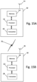
- the DU may be a logical node that includes a subset of the gNB functions, depending on the functional split option. It should be noted that one of ordinary skill in the art would understand that apparatus 10 may include components or features not shown in Fig. 15A .
- apparatus 10 may include a processor 12 for processing information and executing instructions or operations.
- processor 12 may be any type of general or specific purpose processor.
- processor 12 may include one or more of general-purpose computers, special purpose computers, microprocessors, digital signal processors (DSPs), field-programmable gate arrays (FPGAs), application-specific integrated circuits (ASICs), and processors based on a multi-core processor architecture, as examples. While a single processor 12 is shown in Fig. 15A , multiple processors may be utilized according to other embodiments.
- apparatus 10 may include two or more processors that may form a multiprocessor system (e.g., in this case processor 12 may represent a multiprocessor) that may support multiprocessing.
- processor 12 may represent a multiprocessor
- the multiprocessor system may be tightly coupled or loosely coupled (e.g., to form a computer cluster).
- Processor 12 may perform functions associated with the operation of apparatus 10, which may include, for example, precoding of antenna gain/phase parameters, encoding and decoding of individual bits forming a communication message, formatting of information, and overall control of the apparatus 10, including processes related to management of communication or communication resources.
- Apparatus 10 may further include or be coupled to a memory 14 (internal or external), which may be coupled to processor 12, for storing information and instructions that may be executed by processor 12.
- Memory 14 may be one or more memories and of any type suitable to the local application environment, and may be implemented using any suitable volatile or nonvolatile data storage technology such as a semiconductor-based memory device, a magnetic memory device and system, an optical memory device and system, fixed memory, and/or removable memory.
- memory 14 can be comprised of any combination of random access memory (RAM), read only memory (ROM), static storage such as a magnetic or optical disk, hard disk drive (HDD), or any other type of non-transitory machine or computer readable media.
- the instructions stored in memory 14 may include program instructions or computer program code that, when executed by processor 12, enable the apparatus 10 to perform tasks as described herein.
- apparatus 10 may further include or be coupled to (internal or external) a drive or port that is configured to accept and read an external computer readable storage medium, such as an optical disc, USB drive, flash drive, or any other storage medium.
- an external computer readable storage medium such as an optical disc, USB drive, flash drive, or any other storage medium.
- the external computer readable storage medium may store a computer program or software for execution by processor 12 and/or apparatus 10.
- apparatus 10 may also include or be coupled to one or more antennas 15 for transmitting and receiving signals and/or data to and from apparatus 10.
- Apparatus 10 may further include or be coupled to a transceiver 18 configured to transmit and receive information.
- the transceiver 18 may include, for example, a plurality of radio interfaces that may be coupled to the antenna(s) 15.
- the radio interfaces may correspond to a plurality of radio access technologies including one or more of GSM, NB-IoT, LTE, 5G, WLAN, Bluetooth, BT-LE, NFC, radio frequency identifier (RFID), ultrawideband (UWB), MulteFire, and the like.
- the radio interface may include components, such as filters, converters (for example, digital-to-analog converters and the like), mappers, a Fast Fourier Transform (FFT) module, and the like, to generate symbols for a transmission via one or more downlinks and to receive symbols (for example, via an uplink).
- filters for example, digital-to-analog converters and the like
- mappers for example, mappers
- FFT Fast Fourier Transform
- transceiver 18 may be configured to modulate information on to a carrier waveform for transmission by the antenna(s) 15 and demodulate information received via the antenna(s) 15 for further processing by other elements of apparatus 10.
- transceiver 18 may be capable of transmitting and receiving signals or data directly.
- apparatus 10 may include an input and/or output device (I/O device).
- memory 14 may store software modules that provide functionality when executed by processor 12.
- the modules may include, for example, an operating system that provides operating system functionality for apparatus 10.
- the memory may also store one or more functional modules, such as an application or program, to provide additional functionality for apparatus 10.
- the components of apparatus 10 may be implemented in hardware, or as any suitable combination of hardware and software.
- processor 12 and memory 14 may be included in or may form a part of processing circuitry or control circuitry.
- transceiver 18 may be included in or may form a part of transceiver circuitry.
- circuitry may refer to hardware-only circuitry implementations (e.g., analog and/or digital circuitry), combinations of hardware circuits and software, combinations of analog and/or digital hardware circuits with software/firmware, any portions of hardware processor(s) with software (including digital signal processors) that work together to cause an apparatus (e.g., apparatus 10) to perform various functions, and/or hardware circuit(s) and/or processor(s), or portions thereof, that use software for operation but where the software may not be present when it is not needed for operation.
- circuitry may also cover an implementation of merely a hardware circuit or processor (or multiple processors), or portion of a hardware circuit or processor, and its accompanying software and/or firmware.
- circuitry may also cover, for example, a baseband integrated circuit in a server, cellular network node or device, or other computing or network device.
- apparatus 10 may be a network node or RAN node, such as a base station, access point, Node B, eNB, gNB, WLAN access point, or the like.
- apparatus 10 may be controlled by memory 14 and processor 12 to perform the functions associated with any of the embodiments described herein, such as some operations associated with or described with respect to any of the dual DRB/PDCP entity or single DRB/PDCP entity, depicted in Figs. 3-8 .
- apparatus 10 may be controlled to perform a process relating to network coding using a dual DRB/PDCP entity or single DRB/PDCP entity.
- apparatus 10 may be controlled by memory 14 and processor 12 to perform at least the method of Fig. 14A or any other method described herein.
- apparatus 20 may be a node or element in a communications network or associated with such a network, such as a UE, communication node, mobile equipment (ME), mobile station, mobile device, stationary device, IoT device, or other device.
- a UE a node or element in a communications network or associated with such a network
- a UE communication node
- ME mobile equipment
- mobile station mobile device
- stationary device stationary device
- IoT device IoT device
- a UE may alternatively be referred to as, for example, a mobile station, mobile equipment, mobile unit, mobile device, user device, subscriber station, wireless terminal, tablet, smart phone, IoT device, sensor or NB-IoT device, a watch or other wearable, a head-mounted display (HMD), a vehicle, a drone, a medical device and applications thereof (e.g., remote surgery), an industrial device and applications thereof (e.g., a robot and/or other wireless devices operating in an industrial and/or an automated processing chain context), a consumer electronics device, a device operating on commercial and/or industrial wireless networks, or the like.
- apparatus 20 may be implemented in, for instance, a wireless handheld device, a wireless plug-in accessory, or the like.
- apparatus 20 may include one or more processors, one or more computer-readable storage medium (for example, memory, storage, or the like), one or more radio access components (for example, a modem, a transceiver, or the like), and/or a user interface.
- apparatus 20 may be configured to operate using one or more radio access technologies, such as GSM, LTE, LTE-A, NR, 5G, WLAN, WiFi, NB-IoT, Bluetooth, NFC, MulteFire, and/or any other radio access technologies. It should be noted that one of ordinary skill in the art would understand that apparatus 20 may include components or features not shown in Fig. 15B .
- apparatus 20 may include or be coupled to a processor 22 for processing information and executing instructions or operations.
- processor 22 may be any type of general or specific purpose processor.
- processor 22 may include one or more of general-purpose computers, special purpose computers, microprocessors, digital signal processors (DSPs), field-programmable gate arrays (FPGAs), application-specific integrated circuits (ASICs), and processors based on a multi-core processor architecture, as examples. While a single processor 22 is shown in Fig. 15B , multiple processors may be utilized according to other embodiments.
- apparatus 20 may include two or more processors that may form a multiprocessor system (e.g., in this case processor 22 may represent a multiprocessor) that may support multiprocessing.
- processor 22 may represent a multiprocessor
- the multiprocessor system may be tightly coupled or loosely coupled (e.g., to form a computer cluster).
- Processor 22 may perform functions associated with the operation of apparatus 20 including, as some examples, precoding of antenna gain/phase parameters, encoding and decoding of individual bits forming a communication message, formatting of information, and overall control of the apparatus 20, including processes related to management of communication resources.
- Apparatus 20 may further include or be coupled to a memory 24 (internal or external), which may be coupled to processor 22, for storing information and instructions that may be executed by processor 22.
- Memory 24 may be one or more memories and of any type suitable to the local application environment, and may be implemented using any suitable volatile or nonvolatile data storage technology such as a semiconductor-based memory device, a magnetic memory device and system, an optical memory device and system, fixed memory, and/or removable memory.
- memory 24 can be comprised of any combination of random access memory (RAM), read only memory (ROM), static storage such as a magnetic or optical disk, hard disk drive (HDD), or any other type of non-transitory machine or computer readable media.
- the instructions stored in memory 24 may include program instructions or computer program code that, when executed by processor 22, enable the apparatus 20 to perform tasks as described herein.
- apparatus 20 may further include or be coupled to (internal or external) a drive or port that is configured to accept and read an external computer readable storage medium, such as an optical disc, USB drive, flash drive, or any other storage medium.
- an external computer readable storage medium such as an optical disc, USB drive, flash drive, or any other storage medium.
- the external computer readable storage medium may store a computer program or software for execution by processor 22 and/or apparatus 20.
- apparatus 20 may also include or be coupled to one or more antennas 25 for receiving a downlink signal and for transmitting via an uplink from apparatus 20.
- Apparatus 20 may further include a transceiver 28 configured to transmit and receive information.
- the transceiver 28 may also include a radio interface (e.g., a modem) coupled to the antenna 25.
- the radio interface may correspond to a plurality of radio access technologies including one or more of GSM, LTE, LTE-A, 5G, NR, WLAN, NB-IoT, Bluetooth, BT-LE, NFC, RFID, UWB, and the like.
- the radio interface may include other components, such as filters, converters (for example, digital-to-analog converters and the like), symbol demappers, signal shaping components, an Inverse Fast Fourier Transform (IFFT) module, and the like, to process symbols, such as OFDMA symbols, carried by a downlink or an uplink.
- filters for example, digital-to-analog converters and the like
- symbol demappers for example, digital-to-analog converters and the like
- signal shaping components for example, an Inverse Fast Fourier Transform (IFFT) module, and the like
- IFFT Inverse Fast Fourier Transform
- transceiver 28 may be configured to modulate information on to a carrier waveform for transmission by the antenna(s) 25 and demodulate information received via the antenna(s) 25 for further processing by other elements of apparatus 20.
- transceiver 28 may be capable of transmitting and receiving signals or data directly.
- apparatus 20 may include an input and/or output device (I/O device).
- apparatus 20 may further include a user interface, such as a graphical user interface or touchscreen.
- memory 24 stores software modules that provide functionality when executed by processor 22.
- the modules may include, for example, an operating system that provides operating system functionality for apparatus 20.
- the memory may also store one or more functional modules, such as an application or program, to provide additional functionality for apparatus 20.
- the components of apparatus 20 may be implemented in hardware, or as any suitable combination of hardware and software.
- apparatus 20 may optionally be configured to communicate with apparatus 10 via a wireless or wired communications link 70 according to any radio access technology, such as NR.
- processor 22 and memory 24 may be included in or may form a part of processing circuitry or control circuitry.
- transceiver 28 may be included in or may form a part of transceiving circuitry.
- apparatus 20 may be a UE, SL UE, relay UE, mobile device, mobile station, ME, IoT device and/or NB-IoT device, for example.
- apparatus 20 may be controlled to perform a process relating to network coding using a dual DRB/PDCP entity or single DRB/PDCP entity.
- apparatus 20 may be controlled by memory 24 and processor 22 to perform the functions associated with any of the embodiments described herein, such as one or more of the operations illustrated in, or described with respect to, Fig. 14B or any other method described herein.
- an apparatus may include means for performing a method or any of the variants discussed herein, such as the methods described with reference to Figs. 14A and 14B .
- Examples of the means may include one or more processors, memory, and/or computer program code for causing the performance of the operation.
- certain example embodiments provide several technological improvements, enhancements, and/or advantages over existing technological processes and constitute an improvement at least to the technological field of wireless network control and management.
- certain example embodiments provide systems and methods that provide an architecture required for coding (or any quick acknowledgment schemes) within the PDCP sub layer.
- the architecture may be implemented with a specific dual PDCP entity, where original and coded (or duplicate) packets use separate PDCP entities.
- multiple coding methods such as XOR and Reed-Solomon
- example embodiments provide examples of the signaling between the PDCP entities.
- a single DRB/PDCP entity may be provided and that is configured to carry both original PDCP PDUs and network coded PDCP PDUs.
- the PDCP entity delivery functionality may be modified to skip or remove network coded (or duplicate) PDUs in delivery.
- information may be added into the PDU header that causes a legacy UE to ignore a network coded or duplicate PDU.
- a receiver RX_DELIV pointer or counter is provided and when this counter has advanced to a certain threshold, the corresponding network coded PDUs may be removed from the buffer. Accordingly, the use of certain example embodiments results in improved functioning of communications networks and their nodes, such as base stations, eNBs, gNBs, and/or IoT devices, UEs or mobile stations.
- any of the methods, processes, signaling diagrams, algorithms or flow charts described herein may be implemented by software and/or computer program code or portions of code stored in memory or other computer readable or tangible media, and may be executed by a processor.
- an apparatus may include or be associated with at least one software application, module, unit or entity configured as arithmetic operation(s), or as a program or portions of programs (including an added or updated software routine), which may be executed by at least one operation processor or controller.
- Programs also called program products or computer programs, including software routines, applets and macros, may be stored in any apparatus-readable data storage medium and may include program instructions to perform particular tasks.
- a computer program product may include one or more computer-executable components which, when the program is run, are configured to carry out some example embodiments.
- the one or more computer-executable components may be at least one software code or portions of code. Modifications and configurations required for implementing the functionality of an example embodiment may be performed as routine(s), which may be implemented as added or updated software routine(s).
- software routine(s) may be downloaded into the apparatus.
- software or computer program code or portions of code may be in source code form, object code form, or in some intermediate form, and may be stored in some sort of carrier, distribution medium, or computer readable medium, which may be any entity or device capable of carrying the program.
- carrier may include a record medium, computer memory, read-only memory, photoelectrical and/or electrical carrier signal, telecommunications signal, and/or software distribution package, for example.
- the computer program may be executed in a single electronic digital computer or it may be distributed amongst a number of computers.
- the computer readable medium or computer readable storage medium may be a non-transitory medium.
- example embodiments may be performed by hardware or circuitry included in an apparatus, for example through the use of an application specific integrated circuit (ASIC), a programmable gate array (PGA), a field programmable gate array (FPGA), or any other combination of hardware and software.
- ASIC application specific integrated circuit
- PGA programmable gate array
- FPGA field programmable gate array
- the functionality of example embodiments may be implemented as a signal, such as a non-tangible means, that can be carried by an electromagnetic signal downloaded from the Internet or other network.
- an apparatus such as a node, device, or a corresponding component, may be configured as circuitry, a computer or a microprocessor, such as single-chip computer element, or as a chipset, which may include at least a memory for providing storage capacity used for arithmetic operation(s) and/or an operation processor for executing the arithmetic operation(s).
- Example embodiments described herein may apply to both singular and plural implementations, regardless of whether singular or plural language is used in connection with describing certain embodiments.
- an embodiment that describes operations of a single network node may also apply to embodiments that include multiple instances of the network node, and vice versa.
Landscapes
- Engineering & Computer Science (AREA)
- Computer Networks & Wireless Communication (AREA)
- Signal Processing (AREA)
- Mobile Radio Communication Systems (AREA)
Claims (13)
- Verfahren für eine duale Paketdatenkonvergenzprotokollentität, das Folgendes umfasst:Empfangen (1140) einer Vielzahl von ursprünglichen Paketdatenkonvergenzprotokoll(PDCP)-Protokolldateneinheiten, PDUs, an einer zweiten Paketdatenkonvergenzprotokoll(PDCP)-Entität (710), die dediziert ist, netzwerkcodierte Paketdatenkonvergenzprotokollprotokolldateneinheiten zu transportieren, von einer ersten PDCP-Entität (610) für einen Funkträger;Codieren (1142) der ursprünglichen Paketdatenkonvergenzprotokoll(PDCP)-Protokolldateneinheiten, PDUs, an der zweiten Paketdatenkonvergenzprotokoll (PDCP)-Entität, um eine oder mehrere netzwerkcodierte Paketdatenkonvergenzprotokoll(PDCP)-Protokolldateneinheiten, PDUs, zu produzieren; undVerlinken von ursprünglichen Paketdatenkonvergenzprotokoll(PDCP)-Protokolldateneinheiten, PDUs, mit netzwerkcodierten Paketdatenkonvergenzprotokoll(PDCP)-Protokolldateneinheiten, PDUs, durch eine Formel, die dazu ausgelegt ist, die Sequenznummer, SN, der ursprünglichen Paketdatenkonvergenzprotokoll(PDCP)-Protokolldateneinheiten, PDUs, aus der Sequenznummer, SN, der netzwerkcodierten Paketdatenkonvergenzprotokoll(PDCP)-Protokolldateneinheit, PDU, abzuleiten, derart, dass die Sequenznummer, SN, für die netzwerkcodierten Paketdatenkonvergenzprotokoll(PDCP) Protokolldateneinheiten, PDUs, durch die folgende Verlinkungsformel gegeben ist:
SN (1) PDCP1 = SNPDCP2 * n - const (1), SN(2)PDCP1 = SNPDCP2 * n - const (2), ..., SN (n) PDCP1 = SNPDCP2 * n - const (n), wobei der Multiplikator n die Anzahl von ursprünglichen Paketdatenkonvergenzprotokoll(PDCP)-Protokolldateneinheiten, PDUs, ist, die verwendet werden, um eine netzwerkcodierte Paketdatenkonvergenzprotokoll(PDCP)-Protokolldateneinheit PDU zu erstellen, SNPDCP2 die Sequenznummer einer netzwerkcodierten PDCP PDU ist und SN(n)PDCP1 für die ursprüngliche n PDCP PDU ist, die in die netzwerkcodierte PDCP PDU codiert ist, und const(n) eine Konstante für die ursprüngliche n PDCP PDU repräsentiert, die in die netzwerkcodierte PDCP PDU codiert ist. - Verfahren nach Anspruch 1, das ferner Folgendes umfasst:
wenn bei Empfang einer ursprünglichen Paketdatenkonvergenzprotokoll(PDCP)-Protokolldateneinheit, PDU, ein Fehler detektiert wird, Verwenden der Sequenznummer, SN, der ursprünglichen Paketdatenkonvergenzprotokoll(PDCP)-Protokolldateneinheit, PDU, und der Verlinkungsformel, um zu bestimmen, welche ursprünglichen Paketdatenkonvergenzprotokoll(PDCP)-Protokolldateneinheiten, PDUs, und netzwerkcodierten Paketdatenkonvergenzprotokoll(PDCP)-Protokolldateneinheiten, PDUs, zu verwenden sind, um die fehlende ursprüngliche Paketdatenkonvergenzprotokoll(PDCP)-Protokolldateneinheit, PDU, zu rekonstruieren. - Duale Paketdatenkonvergenzprotokollentitätseinrichtung (600), die Folgendes umfasst:eine erste Paketdatenkonvergenzprotokoll(PDCP)-Entität (610) für einen Funkträger, wobei die erste Paketdatenkonvergenzprotokoll(PDCP)-Entität dazu ausgelegt ist, eine oder mehrere ursprüngliche Paketdatenkonvergenzprotokoll(PDCP)-Protokolldateneinheiten, PDUs, zu transportieren; undeine zweite Paketdatenkonvergenzprotokoll(PDCP)-Entität (710), die dediziert ist, netzwerkcodierte Paketdatenkonvergenzprotokollprotokolldateneinheiten für den Funkträger zu transportieren, wobei die zweite Paketdatenkonvergenzprotokoll(PDCP)-Entität dazu ausgelegt ist, eine oder mehrere netzwerkcodierte Paketdatenkonvergenzprotokoll(PDCP)-Protokolldateneinheiten, PDUs, zu transportieren;wobei die zweite Paketdatenkonvergenzprotokoll(PDCP)-Entität zu Folgendem ausgelegt istEmpfangen einer Vielzahl von ursprünglichen Paketdatenkonvergenzprotokoll(PDCP)-Protokolldateneinheiten, PDUs, von der ersten PDCP-Entität für einen Funkträger,Codieren der ursprünglichen Paketdatenkonvergenzprotokoll(PDCP)-Protokolldateneinheiten, PDUs, um eine oder mehrere netzwerkcodierte Paketdatenkonvergenzprotokoll(PDCP)-Protokolldateneinheiten, PDUs, zu produzieren, undVerlinken von ursprünglichen Paketdatenkonvergenzprotokoll(PDCP)-Protokolldateneinheiten, PDUs, mit netzwerkcodierten Paketdatenkonvergenzprotokoll(PDCP)-Protokolldateneinheiten, PDUs, durch eine Formel, die dazu ausgelegt ist, die Sequenznummer, SN, der ursprünglichen Paketdatenkonvergenzprotokoll(PDCP)-Protokolldateneinheiten, PDU, aus der Sequenznummer, SN, der netzwerkcodierten Paketdatenkonvergenzprotokoll(PDCP)-Protokolldateneinheit, PDU, abzuleiten, derart, dass die Sequenznummer, SN, für die netzwerkcodierten Paketdatenkonvergenzprotokoll(PDCP)-Protokolldateneinheiten, PDUs, durch die folgende Verlinkungsformel gegeben ist:
SN (1) PDCP1 = SNPDCP2 * n - const (1), SN (2)PDCP1 = SNPDCP2 * n - const (2), ..., SN (n) PDCP1 = SNPDCP2 * n - const (n), wobei der Multiplikator n die Anzahl von ursprünglichen Paketdatenkonvergenzprotokoll(PDCP)-Protokolldateneinheiten, PDUs, ist, die verwendet werden, um eine netzwerkcodierte Paketdatenkonvergenzprotokoll(PDCP)-Protokolldateneinheit PDU zu erstellen, SNPDCP2 die Sequenznummer einer netzwerkcodierten PDCP PDU ist und SN(n)PDCP1 für die ursprüngliche n PDCP PDU ist, die in die netzwerkcodierte PDCP PDU codiert ist, und const(n) eine Konstante für die ursprüngliche n PDCP PDU repräsentiert, die in die netzwerkcodierte PDCP PDU codiert ist. - Einrichtung nach Anspruch 3, wobei die zweite Paketdatenkonvergenzprotokoll(PDCP)-Entität dazu ausgelegt ist, für die netzwerkcodierten Paketdatenkonvergenzprotokoll(PDCP)-Protokolldateneinheiten, PDUs, ihren eigenen Sequenznummern(SN)-Raum zu verwenden.
- Einrichtung nach Anspruch 3 oder 4, wobei die zweite Paketdatenkonvergenzprotokoll(PDCP)-Entität dazu ausgelegt ist, die netzwerkcodierten Paketdatenkonvergenzprotokoll(PDCP)-Protokolldateneinheiten, PDUs, zur ersten Paketdatenkonvergenzprotokoll(PDCP)-Entität zu übertragen.
- Einrichtung nach einem der Ansprüche 3 bis 5, wobei, wenn eine Vielzahl von Codierverfahren verwendet werden, um die netzwerkcodierten Paketdatenkonvergenzprotokoll(PDCP)-Protokolldateneinheiten, PDUs, zu codieren, die Einrichtung eine separate zweite Paketdatenkonvergenzprotokoll(PDCP)-Entität für jedes der verwendeten Codierverfahren umfasst.
- Einrichtung nach einem der Ansprüche 3 bis 6, wobei die ursprünglichen Paketdatenkonvergenzprotokoll(PDCP)-Protokolldateneinheiten, PDUs, beim Planen auf der Medienzugangssteuerungs(MAC)-Schicht gegenüber den netzwerkcodierten Paketdatenkonvergenzprotokoll(PDCP)-Protokolldateneinheiten, PDUs, priorisiert werden oder die netzwerkcodierten Paketdatenkonvergenzprotokoll(PDCP)-Protokolldateneinheiten, PDUs, an der Medienzugangssteuerungs(MAC)-Schicht vollständig entfernt werden.
- Einrichtung nach einem der Ansprüche 3 bis 7, wobei die zweite Paketdatenkonvergenzprotokoll(PDCP)-Entität dazu ausgelegt ist, einen RX_DELIV-Zähler zu empfangen und, wenn der Zähler einen gewissen Schwellwert erreicht, netzwerkcodierte Paketdatenkonvergenzprotokoll(PDCP)-Protokolldateneinheiten, PDUs, aus dem Puffer der zweiten Paketdatenkonvergenzprotokoll(PDCP)-Entität zu entfernen.
- Einrichtung nach Anspruch 3, wobei die zweite Paketdatenkonvergenzprotokoll(PDCP)-Entität zu Folgendem ausgelegt ist:
wenn bei Empfang einer ursprünglichen Paketdatenkonvergenzprotokoll(PDCP)-Protokolldateneinheit, PDU, ein Fehler detektiert wird, Verwenden der Sequenznummer, SN, der ursprünglichen Paketdatenkonvergenzprotokoll(PDCP)-Protokolldateneinheit, PDU, und der Verlinkungsformel, um zu bestimmen, welche ursprünglichen Paketdatenkonvergenzprotokoll(PDCP)-Protokolldateneinheiten, PDUs, und netzwerkcodierten Paketdatenkonvergenzprotokoll(PDCP)-Protokolldateneinheiten, PDUs, zu verwenden sind, um die fehlende ursprüngliche Paketdatenkonvergenzprotokoll(PDCP)-Protokolldateneinheit, PDU, zu rekonstruieren. - Einrichtung nach einem der Ansprüche 3 bis 9, wobei die Einrichtung mindestens eines von einer Basisstation, einem gNB, einer Teilnehmereinrichtung, einer Sidelink-Teilnehmereinrichtung oder einer Fahrzeug-zu-allem-Vorrichtung umfasst.
- Verfahren für eine einzelne Paketdatenkonvergenzprotokollentität, das Folgendes umfasst:Puffern (150) von ursprünglichen Paketdatenkonvergenzprotokoll(PDCP)-Protokolldateneinheiten, PDUs, durch eine übertragende Seite (810) einer Paketdatenkonvergenzprotokoll(PDCP)-Entität (410);Codieren (1152) der ursprünglichen Paketdatenkonvergenzprotokoll(PDCP)-Protokolldateneinheiten, PDUs, auf der übertragenden Seite, um netzwerkcodierte Paketdatenkonvergenzprotokoll(PDCP)-Protokolldateneinheiten, PDUs, zu produzieren, wo jedes netzwerkcodierte PDCP zwei ursprüngliche PDCP PDUs codiert, undVerlinken der ursprünglichen Paketdatenkonvergenzprotokoll(PDCP)-Protokolldateneinheiten, PDUs, mit netzwerkcodierten Paketdatenkonvergenzprotokoll(PDCP)-Protokolldateneinheiten, PDUs, durch eine Formel, die dazu ausgelegt ist, die Sequenznummer, SN, der ursprünglichen Paketdatenkonvergenzprotokoll(PDCP)-Protokolldateneinheit, PDU, aus der Sequenznummer, SN, der netzwerkcodierten Paketdatenkonvergenzprotokoll(PDCP)-Protokolldateneinheit, PDU, abzuleiten, wobei die Sequenznummer, SN, einer ursprünglichen Paketdatenkonvergenzprotokoll(PDCP)-Protokolldateneinheit, PDU, durch die folgende Formel abgeletet wird:
SNoriginal (1) = SNcoded - const (1) und SNoriginal (2) = SNcoded - const (2), wo codierte Sequenznummern SNs jene Sequenznummern SNs sind, für die (SN + const(3))-Modulo 3 = 0. - Einzelne Paketdatenkonvergenzprotokollentitätseinrichtung, die Folgendes umfasst:eine Paketdatenkonvergenzprotokoll(PDCP)-Entität (410), die eine übertragende Seite (810) und eine empfangende Seite (820) umfasst,wobei die übertragende Seite zu Folgendem ausgelegt istPuffern von ursprünglichen Paketdatenkonvergenzprotokoll(PDCP)-Protokolldateneinheiten, PDUs;Codieren der ursprünglichen Paketdatenkonvergenzprotokoll(PDCP)-Protokolldateneinheiten, PDUs, um netzwerkcodierte Paketdatenkonvergenzprotokoll(PDCP)-Protokolldateneinheiten, PDUs, zu produzieren, wo jede netzwerkcodierte PDCP PDU zwei ursprüngliche PDCP PDUs codiert; undwobei die Datenfunkträger, DRB, oder die Paketdatenkonvergenzprotokoll(PDCP)-Entität zu Folgendem ausgelegt ist:Verlinken der ursprünglichen Paketdatenkonvergenzprotokoll(PDCP)-Protokolldateneinheiten, PDUs, mit netzwerkcodierten Paketdatenkonvergenzprotokoll(PDCP)-Protokolldateneinheiten, PDUs, durch eine Formel, die dazu ausgelegt ist, die Sequenznummer, SN, der ursprünglichen Paketdatenkonvergenzprotokoll(PDCP)-Protokolldateneinheit, PDU, aus der Sequenznummer, SN, der netzwerkcodierten Paketdatenkonvergenzprotokoll(PDCP)-Protokolldateneinheit, PDU, abzuleiten, wobei die Sequenznummer, SN, einer ursprünglichen Paketdatenkonvergenzprotokoll(PDCP)-Protokolldateneinheit, PDU, durch die folgende Formel abgeletet wird:
SNoriginal (1) = SNcoded - const (1) und SNoriginal (2) = SNcoded - const (2), wo codierte Sequenznummern, SNs, jene Sequenznummern SNs sind, für die (SN + const(3))-Modulo 3 = 0. - Einrichtung nach Anspruch 12, wobei den codierten Paketdatenkonvergenzprotokolll(PDCP)-Protokolldateneinheiten, PDUs, eine Sequenznummer, SN, gegeben wird.
Applications Claiming Priority (1)
| Application Number | Priority Date | Filing Date | Title |
|---|---|---|---|
| PCT/EP2020/085542 WO2022122159A1 (en) | 2020-12-10 | 2020-12-10 | Network coding with packet data convergence protocol (pdcp) entity |
Publications (2)
| Publication Number | Publication Date |
|---|---|
| EP4260652A1 EP4260652A1 (de) | 2023-10-18 |
| EP4260652B1 true EP4260652B1 (de) | 2025-01-15 |
Family
ID=73835590
Family Applications (1)
| Application Number | Title | Priority Date | Filing Date |
|---|---|---|---|
| EP20824517.5A Active EP4260652B1 (de) | 2020-12-10 | 2020-12-10 | Netzwerkcodierung mit einheit des paketdatenkonvergenzprotokolls (pdcp) |
Country Status (3)
| Country | Link |
|---|---|
| US (1) | US20250024320A1 (de) |
| EP (1) | EP4260652B1 (de) |
| WO (1) | WO2022122159A1 (de) |
Families Citing this family (2)
| Publication number | Priority date | Publication date | Assignee | Title |
|---|---|---|---|---|
| CN117202255A (zh) * | 2022-05-31 | 2023-12-08 | 大唐移动通信设备有限公司 | 数据单元处理方法、装置及通信设备 |
| US20250380186A1 (en) * | 2024-06-07 | 2025-12-11 | Interdigital Patent Holdings, Inc. | Methods, architectures, apparatuses and systems for evaluation of successful transmissions |
Family Cites Families (6)
| Publication number | Priority date | Publication date | Assignee | Title |
|---|---|---|---|---|
| CN104753627A (zh) * | 2013-12-26 | 2015-07-01 | 中兴通讯股份有限公司 | 多路径传输方法、系统及数据发送装置和数据接收装置 |
| US12224860B1 (en) * | 2014-01-30 | 2025-02-11 | Genghiscomm Holdings, LLC | Linear coding in decentralized networks |
| KR101603556B1 (ko) * | 2015-10-22 | 2016-03-15 | 홍익대학교 산학협력단 | 데이터 전송 시스템, 부호화 장치 및 부호화 방법 |
| US10855814B2 (en) * | 2017-10-20 | 2020-12-01 | Comcast Cable Communications, Llc | Non-access stratum capability information |
| US10582507B2 (en) * | 2018-05-17 | 2020-03-03 | At&T Intellectual Property I, L.P. | Network coding for bandwidth efficient reliability improvement for URLLC service |
| WO2020210682A1 (en) * | 2019-04-12 | 2020-10-15 | Apple Inc. | Network coding at the packet data convergence protocol (pdcp) layer to increase communication reliability |
-
2020
- 2020-12-10 EP EP20824517.5A patent/EP4260652B1/de active Active
- 2020-12-10 US US18/256,574 patent/US20250024320A1/en active Pending
- 2020-12-10 WO PCT/EP2020/085542 patent/WO2022122159A1/en not_active Ceased
Also Published As
| Publication number | Publication date |
|---|---|
| US20250024320A1 (en) | 2025-01-16 |
| WO2022122159A1 (en) | 2022-06-16 |
| EP4260652A1 (de) | 2023-10-18 |
Similar Documents
| Publication | Publication Date | Title |
|---|---|---|
| JP7459127B2 (ja) | 無線通信システムにおいて、複数のビームを介して信号を送受信する方法及びその装置 | |
| CN113544991B (zh) | 用于在nr v2x中发送psfch的方法和设备 | |
| KR102674850B1 (ko) | Nr 시스템에서 mr-dc에 대한 단말 능력을 보고하는 방법 및 장치 | |
| CN112425202B (zh) | 下一代移动通信系统中分类和处理sdap控制pdu的方法及相关装置 | |
| KR102376115B1 (ko) | 차세대 이동 통신 시스템에서 pdcp 버전 변경에 따른 재설정 방법 및 장치 | |
| US12028759B2 (en) | Method and apparatus for performing handover procedure in wireless communication system | |
| US11381354B2 (en) | Method and apparatus for wireless communication of wireless node in wireless communication system | |
| KR102628039B1 (ko) | 무선 통신 시스템에서 데이터를 송수신하는 방법 및 장치 | |
| KR102810779B1 (ko) | 차세대 무선 통신 시스템에서 자동 이웃 관계 형성을 위한 노드 간 협업 방법 | |
| CN112262543A (zh) | 在下一代移动通信系统中指示半持续探测参考信号作为相邻小区参考信号的方法和装置 | |
| KR102788913B1 (ko) | 무선 통신 시스템에서 통신을 수행하는 방법 및 장치 | |
| KR20210006884A (ko) | 비-지상 네트워크용 하이브리드 자동 반복 요청(harq) 기술 | |
| CN111034079A (zh) | 数据传输方法、设备和通信系统 | |
| KR20200032560A (ko) | 무선 통신 시스템에서 데이터를 송수신하는 방법 및 장치 | |
| CN106992846A (zh) | 一种数据发送方法、数据接收方法和装置 | |
| CN113261332B (zh) | 用于在无线通信系统中发送或接收数据的方法和装置 | |
| KR20210076740A (ko) | 차세대 이동통신 시스템에서 rrc 메시지의 분할 전송과 관련된 타이머 관리 방법 및 장치 | |
| CN110178358A (zh) | 无线通信系统中处理数据的方法和装置 | |
| CN116724511A (zh) | 用于网络协作通信的harq-ack反馈发送或接收的方法和设备 | |
| KR20210020470A (ko) | 차세대 이동 통신 시스템에서 상향 링크를 지원하기 위한 mimo 설정 방법 및 장치 | |
| US20210297915A1 (en) | Packet data convergence protocol (pdcp) protocol data unit (pdu) handling for mobility between new radio access technology and long term evolution | |
| KR20240108684A (ko) | 무선 통신 시스템에서 QoE 설정 및 보고하는 방법 및 장치 | |
| EP4260652B1 (de) | Netzwerkcodierung mit einheit des paketdatenkonvergenzprotokolls (pdcp) | |
| KR20230008501A (ko) | 이동통신 시스템에서 동시에 여러 개의 캐리어에 대한 pdcch 수신 빔을 활성화하는 방법 및 장치 | |
| KR102760790B1 (ko) | 차세대 무선 통신 시스템에서 랜덤 액세스 없이 셀접속을 수행하는 방법 |
Legal Events
| Date | Code | Title | Description |
|---|---|---|---|
| STAA | Information on the status of an ep patent application or granted ep patent |
Free format text: STATUS: UNKNOWN |
|
| STAA | Information on the status of an ep patent application or granted ep patent |
Free format text: STATUS: THE INTERNATIONAL PUBLICATION HAS BEEN MADE |
|
| PUAI | Public reference made under article 153(3) epc to a published international application that has entered the european phase |
Free format text: ORIGINAL CODE: 0009012 |
|
| STAA | Information on the status of an ep patent application or granted ep patent |
Free format text: STATUS: REQUEST FOR EXAMINATION WAS MADE |
|
| 17P | Request for examination filed |
Effective date: 20230710 |
|
| AK | Designated contracting states |
Kind code of ref document: A1 Designated state(s): AL AT BE BG CH CY CZ DE DK EE ES FI FR GB GR HR HU IE IS IT LI LT LU LV MC MK MT NL NO PL PT RO RS SE SI SK SM TR |
|
| DAV | Request for validation of the european patent (deleted) | ||
| DAX | Request for extension of the european patent (deleted) | ||
| STAA | Information on the status of an ep patent application or granted ep patent |
Free format text: STATUS: EXAMINATION IS IN PROGRESS |
|
| 17Q | First examination report despatched |
Effective date: 20240321 |
|
| GRAP | Despatch of communication of intention to grant a patent |
Free format text: ORIGINAL CODE: EPIDOSNIGR1 |
|
| STAA | Information on the status of an ep patent application or granted ep patent |
Free format text: STATUS: GRANT OF PATENT IS INTENDED |
|
| INTG | Intention to grant announced |
Effective date: 20241008 |
|
| GRAS | Grant fee paid |
Free format text: ORIGINAL CODE: EPIDOSNIGR3 |
|
| GRAA | (expected) grant |
Free format text: ORIGINAL CODE: 0009210 |
|
| STAA | Information on the status of an ep patent application or granted ep patent |
Free format text: STATUS: THE PATENT HAS BEEN GRANTED |
|
| AK | Designated contracting states |
Kind code of ref document: B1 Designated state(s): AL AT BE BG CH CY CZ DE DK EE ES FI FR GB GR HR HU IE IS IT LI LT LU LV MC MK MT NL NO PL PT RO RS SE SI SK SM TR |
|
| REG | Reference to a national code |
Ref country code: CH Ref legal event code: EP Ref country code: GB Ref legal event code: FG4D |
|
| REG | Reference to a national code |
Ref country code: DE Ref legal event code: R096 Ref document number: 602020044918 Country of ref document: DE |
|
| REG | Reference to a national code |
Ref country code: IE Ref legal event code: FG4D |
|
| REG | Reference to a national code |
Ref country code: NL Ref legal event code: MP Effective date: 20250115 |
|
| PG25 | Lapsed in a contracting state [announced via postgrant information from national office to epo] |
Ref country code: NL Free format text: LAPSE BECAUSE OF FAILURE TO SUBMIT A TRANSLATION OF THE DESCRIPTION OR TO PAY THE FEE WITHIN THE PRESCRIBED TIME-LIMIT Effective date: 20250115 |
|
| PG25 | Lapsed in a contracting state [announced via postgrant information from national office to epo] |
Ref country code: RS Free format text: LAPSE BECAUSE OF FAILURE TO SUBMIT A TRANSLATION OF THE DESCRIPTION OR TO PAY THE FEE WITHIN THE PRESCRIBED TIME-LIMIT Effective date: 20250415 |
|
| PG25 | Lapsed in a contracting state [announced via postgrant information from national office to epo] |
Ref country code: FI Free format text: LAPSE BECAUSE OF FAILURE TO SUBMIT A TRANSLATION OF THE DESCRIPTION OR TO PAY THE FEE WITHIN THE PRESCRIBED TIME-LIMIT Effective date: 20250115 |
|
| PG25 | Lapsed in a contracting state [announced via postgrant information from national office to epo] |
Ref country code: PL Free format text: LAPSE BECAUSE OF FAILURE TO SUBMIT A TRANSLATION OF THE DESCRIPTION OR TO PAY THE FEE WITHIN THE PRESCRIBED TIME-LIMIT Effective date: 20250115 |
|
| PG25 | Lapsed in a contracting state [announced via postgrant information from national office to epo] |
Ref country code: ES Free format text: LAPSE BECAUSE OF FAILURE TO SUBMIT A TRANSLATION OF THE DESCRIPTION OR TO PAY THE FEE WITHIN THE PRESCRIBED TIME-LIMIT Effective date: 20250115 |
|
| REG | Reference to a national code |
Ref country code: LT Ref legal event code: MG9D |
|
| PG25 | Lapsed in a contracting state [announced via postgrant information from national office to epo] |
Ref country code: NO Free format text: LAPSE BECAUSE OF FAILURE TO SUBMIT A TRANSLATION OF THE DESCRIPTION OR TO PAY THE FEE WITHIN THE PRESCRIBED TIME-LIMIT Effective date: 20250415 Ref country code: IS Free format text: LAPSE BECAUSE OF FAILURE TO SUBMIT A TRANSLATION OF THE DESCRIPTION OR TO PAY THE FEE WITHIN THE PRESCRIBED TIME-LIMIT Effective date: 20250515 |
|
| REG | Reference to a national code |
Ref country code: AT Ref legal event code: MK05 Ref document number: 1760657 Country of ref document: AT Kind code of ref document: T Effective date: 20250115 |
|
| PG25 | Lapsed in a contracting state [announced via postgrant information from national office to epo] |
Ref country code: HR Free format text: LAPSE BECAUSE OF FAILURE TO SUBMIT A TRANSLATION OF THE DESCRIPTION OR TO PAY THE FEE WITHIN THE PRESCRIBED TIME-LIMIT Effective date: 20250115 |
|
| PG25 | Lapsed in a contracting state [announced via postgrant information from national office to epo] |
Ref country code: LV Free format text: LAPSE BECAUSE OF FAILURE TO SUBMIT A TRANSLATION OF THE DESCRIPTION OR TO PAY THE FEE WITHIN THE PRESCRIBED TIME-LIMIT Effective date: 20250115 Ref country code: PT Free format text: LAPSE BECAUSE OF FAILURE TO SUBMIT A TRANSLATION OF THE DESCRIPTION OR TO PAY THE FEE WITHIN THE PRESCRIBED TIME-LIMIT Effective date: 20250515 |
|
| PG25 | Lapsed in a contracting state [announced via postgrant information from national office to epo] |
Ref country code: GR Free format text: LAPSE BECAUSE OF FAILURE TO SUBMIT A TRANSLATION OF THE DESCRIPTION OR TO PAY THE FEE WITHIN THE PRESCRIBED TIME-LIMIT Effective date: 20250416 Ref country code: BG Free format text: LAPSE BECAUSE OF FAILURE TO SUBMIT A TRANSLATION OF THE DESCRIPTION OR TO PAY THE FEE WITHIN THE PRESCRIBED TIME-LIMIT Effective date: 20250115 |
|
| PG25 | Lapsed in a contracting state [announced via postgrant information from national office to epo] |
Ref country code: AT Free format text: LAPSE BECAUSE OF FAILURE TO SUBMIT A TRANSLATION OF THE DESCRIPTION OR TO PAY THE FEE WITHIN THE PRESCRIBED TIME-LIMIT Effective date: 20250115 |
|
| PG25 | Lapsed in a contracting state [announced via postgrant information from national office to epo] |
Ref country code: SE Free format text: LAPSE BECAUSE OF FAILURE TO SUBMIT A TRANSLATION OF THE DESCRIPTION OR TO PAY THE FEE WITHIN THE PRESCRIBED TIME-LIMIT Effective date: 20250115 |
|
| PG25 | Lapsed in a contracting state [announced via postgrant information from national office to epo] |
Ref country code: SM Free format text: LAPSE BECAUSE OF FAILURE TO SUBMIT A TRANSLATION OF THE DESCRIPTION OR TO PAY THE FEE WITHIN THE PRESCRIBED TIME-LIMIT Effective date: 20250115 |
|
| PG25 | Lapsed in a contracting state [announced via postgrant information from national office to epo] |
Ref country code: DK Free format text: LAPSE BECAUSE OF FAILURE TO SUBMIT A TRANSLATION OF THE DESCRIPTION OR TO PAY THE FEE WITHIN THE PRESCRIBED TIME-LIMIT Effective date: 20250115 |
|
| PG25 | Lapsed in a contracting state [announced via postgrant information from national office to epo] |
Ref country code: IT Free format text: LAPSE BECAUSE OF FAILURE TO SUBMIT A TRANSLATION OF THE DESCRIPTION OR TO PAY THE FEE WITHIN THE PRESCRIBED TIME-LIMIT Effective date: 20250115 |
|
| REG | Reference to a national code |
Ref country code: DE Ref legal event code: R097 Ref document number: 602020044918 Country of ref document: DE |
|
| PG25 | Lapsed in a contracting state [announced via postgrant information from national office to epo] |
Ref country code: EE Free format text: LAPSE BECAUSE OF FAILURE TO SUBMIT A TRANSLATION OF THE DESCRIPTION OR TO PAY THE FEE WITHIN THE PRESCRIBED TIME-LIMIT Effective date: 20250115 Ref country code: CZ Free format text: LAPSE BECAUSE OF FAILURE TO SUBMIT A TRANSLATION OF THE DESCRIPTION OR TO PAY THE FEE WITHIN THE PRESCRIBED TIME-LIMIT Effective date: 20250115 |
|
| PG25 | Lapsed in a contracting state [announced via postgrant information from national office to epo] |
Ref country code: RO Free format text: LAPSE BECAUSE OF FAILURE TO SUBMIT A TRANSLATION OF THE DESCRIPTION OR TO PAY THE FEE WITHIN THE PRESCRIBED TIME-LIMIT Effective date: 20250115 |
|
| PG25 | Lapsed in a contracting state [announced via postgrant information from national office to epo] |
Ref country code: SK Free format text: LAPSE BECAUSE OF FAILURE TO SUBMIT A TRANSLATION OF THE DESCRIPTION OR TO PAY THE FEE WITHIN THE PRESCRIBED TIME-LIMIT Effective date: 20250115 |
|
| PLBE | No opposition filed within time limit |
Free format text: ORIGINAL CODE: 0009261 |
|
| STAA | Information on the status of an ep patent application or granted ep patent |
Free format text: STATUS: NO OPPOSITION FILED WITHIN TIME LIMIT |
|
| 26N | No opposition filed |
Effective date: 20251016 |
|
| PGFP | Annual fee paid to national office [announced via postgrant information from national office to epo] |
Ref country code: DE Payment date: 20251104 Year of fee payment: 6 |
|
| PGFP | Annual fee paid to national office [announced via postgrant information from national office to epo] |
Ref country code: GB Payment date: 20251030 Year of fee payment: 6 |
|
| PGFP | Annual fee paid to national office [announced via postgrant information from national office to epo] |
Ref country code: FR Payment date: 20251110 Year of fee payment: 6 |