EP4260678B1 - Dispositif de coupe en rouleau de tonte de gazon entraîné par un moteur à rotor externe intégré et outil d'entretien de gazon - Google Patents
Dispositif de coupe en rouleau de tonte de gazon entraîné par un moteur à rotor externe intégré et outil d'entretien de gazon Download PDFInfo
- Publication number
- EP4260678B1 EP4260678B1 EP21908297.1A EP21908297A EP4260678B1 EP 4260678 B1 EP4260678 B1 EP 4260678B1 EP 21908297 A EP21908297 A EP 21908297A EP 4260678 B1 EP4260678 B1 EP 4260678B1
- Authority
- EP
- European Patent Office
- Prior art keywords
- outer rotor
- motor
- reel
- rotor motor
- built
- Prior art date
- Legal status (The legal status is an assumption and is not a legal conclusion. Google has not performed a legal analysis and makes no representation as to the accuracy of the status listed.)
- Active
Links
Images

Classifications
-
- A—HUMAN NECESSITIES
- A01—AGRICULTURE; FORESTRY; ANIMAL HUSBANDRY; HUNTING; TRAPPING; FISHING
- A01D—HARVESTING; MOWING
- A01D34/00—Mowers; Mowing apparatus of harvesters
- A01D34/01—Mowers; Mowing apparatus of harvesters characterised by features relating to the type of cutting apparatus
- A01D34/412—Mowers; Mowing apparatus of harvesters characterised by features relating to the type of cutting apparatus having rotating cutters
- A01D34/42—Mowers; Mowing apparatus of harvesters characterised by features relating to the type of cutting apparatus having rotating cutters having cutters rotating about a horizontal axis, e.g. cutting-cylinders
- A01D34/46—Mowers; Mowing apparatus of harvesters characterised by features relating to the type of cutting apparatus having rotating cutters having cutters rotating about a horizontal axis, e.g. cutting-cylinders hand-guided by a walking operator
- A01D34/47—Mowers; Mowing apparatus of harvesters characterised by features relating to the type of cutting apparatus having rotating cutters having cutters rotating about a horizontal axis, e.g. cutting-cylinders hand-guided by a walking operator with motor driven cutters or wheels
- A01D34/475—Driving mechanisms
-
- A—HUMAN NECESSITIES
- A01—AGRICULTURE; FORESTRY; ANIMAL HUSBANDRY; HUNTING; TRAPPING; FISHING
- A01B—SOIL WORKING IN AGRICULTURE OR FORESTRY; PARTS, DETAILS, OR ACCESSORIES OF AGRICULTURAL MACHINES OR IMPLEMENTS, IN GENERAL
- A01B39/00—Machines specially adapted for working soil on which crops are growing
- A01B39/12—Machines specially adapted for working soil on which crops are growing for special purposes, e.g. for special culture
- A01B39/18—Machines specially adapted for working soil on which crops are growing for special purposes, e.g. for special culture for weeding
-
- A—HUMAN NECESSITIES
- A01—AGRICULTURE; FORESTRY; ANIMAL HUSBANDRY; HUNTING; TRAPPING; FISHING
- A01B—SOIL WORKING IN AGRICULTURE OR FORESTRY; PARTS, DETAILS, OR ACCESSORIES OF AGRICULTURAL MACHINES OR IMPLEMENTS, IN GENERAL
- A01B71/00—Construction or arrangement of setting or adjusting mechanisms, of implement or tool drive or of power take-off; Means for protecting parts against dust, or the like; Adapting machine elements to or for agricultural purposes
-
- A—HUMAN NECESSITIES
- A01—AGRICULTURE; FORESTRY; ANIMAL HUSBANDRY; HUNTING; TRAPPING; FISHING
- A01D—HARVESTING; MOWING
- A01D34/00—Mowers; Mowing apparatus of harvesters
- A01D34/01—Mowers; Mowing apparatus of harvesters characterised by features relating to the type of cutting apparatus
- A01D34/412—Mowers; Mowing apparatus of harvesters characterised by features relating to the type of cutting apparatus having rotating cutters
- A01D34/42—Mowers; Mowing apparatus of harvesters characterised by features relating to the type of cutting apparatus having rotating cutters having cutters rotating about a horizontal axis, e.g. cutting-cylinders
- A01D34/56—Driving mechanisms for the cutters
- A01D34/58—Driving mechanisms for the cutters electric
-
- A—HUMAN NECESSITIES
- A01—AGRICULTURE; FORESTRY; ANIMAL HUSBANDRY; HUNTING; TRAPPING; FISHING
- A01D—HARVESTING; MOWING
- A01D34/00—Mowers; Mowing apparatus of harvesters
- A01D34/01—Mowers; Mowing apparatus of harvesters characterised by features relating to the type of cutting apparatus
- A01D34/412—Mowers; Mowing apparatus of harvesters characterised by features relating to the type of cutting apparatus having rotating cutters
- A01D34/42—Mowers; Mowing apparatus of harvesters characterised by features relating to the type of cutting apparatus having rotating cutters having cutters rotating about a horizontal axis, e.g. cutting-cylinders
- A01D34/52—Cutting apparatus
- A01D34/53—Helically shaped cutting members
Definitions
- the present invention relates to lawn care devices, and more particularly, to a mowing cylinder cutter and a lawn care tool driven by a built-in outer rotor motor.
- the lawn care device for example, the cylinder mower
- the cylinder cutter of the motorized cylinder mower generally adopts chain drive, which is complicated.
- the cylinder cutter drive of the electric cylinder mower on the market is mostly the same as that of the motorized cylinder mower, and it may alternatively adopt a motor provided on the side of the frame.
- the cylinder cutter for mowing the lawn can be replaced by a working part for lawn care operations such as root cutting and grass grooming.
- JP2013123392A discloses a lawn mower adapted to mow a lawn by rotating a reel blade taking a mowing motor as a driving source.
- a mowing motor an outer rotor motor capable of outputting a low speed high torque is used, and the mowing motor is built in the interior of the reel blade to make a direct drive type.
- US2005/257512A1 discloses a walk-behind greens mower having a mobile structure and a ground engaging traction member rotatably coupled to the mobile structure.
- the ground engaging traction member imparts traction movement to the mobile structure for movement on the ground at a ground speed.
- An internal combustion engine is supported on the mobile structure and outputs a driving force to the ground engaging traction member.
- a bed knife is supported by the mobile structure having a cutting edge that cooperates with a grass cutting reel rotatably supported on the mobile structure.
- An electric motor supported on the mobile structure rotatably driving the grass cutting reel at a rotational speed that can vary depending upon the detected ground speed.
- JP201 1 142845A discloses a lawn mowing vehicle.
- the lawn mowing vehicle which includes at least a front lawn mower and a front lawn mower arranged at different positions in the right and left direction of the vehicle relative to the advancing direction, includes: a first lifting and lowering mechanism for lifting and lowering the front lawn mower by an electric cylinder; a second lifting and lowering mechanism for lifting and lowering the front lawn mower by an electric cylinder; and a controller that controls the first and the second lifting and lowering mechanisms and individually lifts and lowers the front lawn mower and the front lawn mower.
- CN108115302A discloses a machining method of grass-cutting hob.
- the method includes: welding hob blades to cutter heads; placing the hob in a thermal treatment furnace with the temperature in the furnace being 890-890 DEG C for thermal treatment, keeping the temperature for 1-1.5 hours, taking out the hob, placing into oil for oil quenching for 2-3 minutes, and performing air cooling until the hob reaches room temperature; annealing at 340-355 DEG C, keeping the temperature for 2-3 hours, and naturally cooling to room temperature; grinding the excircle of the hob to allow the outer edges of the hob blades to be located on the same cylindrical surface; meanwhile, grinding the bearing section of a hob shaft to allow the axis of the bearing section to coincide with the rotation axis of the hob blades; grinding the edge back angle alpha of the hob blades; performing sand blasting on the hob, and then performing paint spraying; performing paint baking; grinding the edge point angle beta of the hob blade to complete the machining of the hob.
- US2017/156265A1 discloses an embedded-outer rotor motor direct driven mower driving wheel and a mower.
- the embedded-outer rotor motor direct driven mower driving wheel comprises a driving wheel main body formed by the assembling of a wheel side cover I, a wheel side cover II, and a wheel body sandwiched between the wheel side cover I and the wheel side cover II, the wheel side cover I, the wheel side cover II and the wheel body are enclosed to define a cavity, an outer rotor motor is mounted in the cavity, an outer rotor portion of the outer rotor motor is fixedly arranged relative to the driving wheel main body, an internal stator portion of the outer rotor motor is provided with a fixed shaft penetrating through the wheel side cover I and extending out of the driving wheel main body, and the wheel side cover I is provided with a shaft hole I allowing the fixed shaft to penetrate through.
- DE3921068A1 discloses an electric driven hand operated lawn mower which has motor housing rotating around fixed motor shaft and is provided with spiral shaped blades.
- An objective of the present invention is to provide a mowing cylinder cutter driven by a built-in outer rotor motor.
- the present invention is driven by a built-in outer rotor motor, which simplifies the transmission structure, improves work efficiency, and makes the whole structure compact.
- a mowing cylinder cutter driven by a built-in outer rotor motor includes an outer rotor motor, blades and a reel, where the outer rotor motor includes a stator assembly and an outer rotor; the stator assembly is connected to a frame through a connecting member; and the blades are multiple and spiral.
- the blades are fixedly connected to the reel through a plurality of support plates, such that there is no direct contact between the reel and the blades; at least one end of the reel is provided with the outer rotor motor, such that the end of the reel is surrounded by the outer rotor motor; and the outer rotor is fixedly connected to the reel and the blades, such that the blades are fixedly connected to both the outer rotor and the reel at the same time.
- the connecting member may be a motor shaft;
- the reel may be shaped as a hollow straight cylinder or a variable-diameter cylinder; one end or two ends of the reel may be provided with a motor compartment; the motor shaft passes through the reel, and two ends of the motor shaft may extend out of the reel; and the two ends of the motor shaft may be provided with flat positions, and the motor shaft may be fixedly connected to the frame through the flat positions.
- one end of the reel may be provided with an outer rotor motor and a motor compartment; the outer rotor motor may be provided in the motor compartment; and the stator assembly may be circumferentially limited to the motor shaft through a key.
- two ends of the reel may be respectively provided with outer rotor motors and motor compartments; two outer rotor motors may be respectively provided in the corresponding motor compartments; the stator assembly includes a first sleeve and a stator coil; the stator coil may be provided on the first sleeve; and the first sleeve may be provided on the motor shaft and may be circumferentially limited through a key.
- the motor compartment may be a part of the reel; the motor compartment may be provided with an opening facing outward; the outer rotor motor may be provided in the motor compartment from the opening; an end cap may be provided on an outer side of the outer rotor motor; the end cap may be integrally formed with the outer rotor, and may be matched with the motor compartment to seal the outer rotor motor in the motor compartment; a center of the end cap may be provided with a bearing; and the motor shaft may be connected to and passes through the bearing.
- one end or two ends of the reel may be provided with an outer rotor motor;
- the connecting member includes a second sleeve being hollow and cylindrical;
- the stator assembly includes a stator coil;
- the stator coil may be provided on the second sleeve of the connecting member;
- the second sleeve may be sleeved on the reel and has a gap with the reel;
- an outer end of the second sleeve and an end of the outer rotor form a radial labyrinth seal;
- an end of the reel adjacent to an outer side of the second sleeve may be provided with a bearing;
- the bearing may be provided in a bearing seat; and the bearing seat may be fixedly connected to the second sleeve.
- the bearing seat and the connecting member may be integrally formed; and/or, an inner end of the outer rotor extends axially to the reel; and/or, an outer end of the outer rotor extends radially to form a flange; an outer end surface of the flange may be provided with at least one annular notch; an outer end of the connecting member extends to the flange; an end surface of the connecting member facing the flange may be correspondingly provided with at least one annular lug boss; and the lug boss may be inserted into the notch, such that the outer end of the connecting member and the outer end of the outer rotor form the radial labyrinth seal.
- the present invention has the following advantages.
- the outer rotor motor is provided inside the cylinder cutter or the working part, and the cylinder cutter or the working part is driven to rotate through the outer rotor of the motor.
- the present invention achieves a compact structure and high transmission efficiency. This design avoids additional efficiency loss, and greatly improves the work efficiency.
- the direct drive of the outer rotor motor improves the working torque and can cope with a complex working environment.
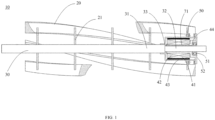
- FIG. 1 shows a major structure of a mowing cylinder cutter driven by a built-in outer rotor motor according to a first embodiment of the present invention.
- the mowing cylinder cutter 10 driven by a built-in outer rotor motor includes blades 20 and a reel 30.
- the blades 20 are multiple and spiral, and the blades 20 are fixedly connected to the reel 30 through a plurality of support plates 21 respectively.
- An outer rotor motor 41 is provided at one end of the reel 30.
- the outer rotor motor 41 includes a stator assembly 42 and an outer rotor 43.
- the stator assembly 42 is connected to a frame (not shown) through a connecting member 44, and the frame may be a frame of a lawn mower.
- the outer rotor 43 is connected to the reel 30.
- connection between the outer rotor 43 and the reel 30 may be a direct connection, that is, the outer rotor 43 is directly connected to the reel 30. It may also be an indirectly connection.
- the outer rotor 43 is connected to the reel 30 through the support plate 21 or the blade 20 or other component connected to the reel 30. Any connection is acceptable as long as the outer rotor 43 can drive the reel 30 to rotate.
- the outer rotor motor 41 may be provided at one or both ends of the reel 30. That is, the reel 30 may be provided with an outer rotor motor 41 at only one end, or may be provided with an outer rotor motor 41 at each end.
- the blades 20, the reel 30 and the support plates 21 are fixedly connected by welding.
- the outer rotor 43 is fixedly connected to the blades 20 and the reel 30 through the support plates 21.
- the outer rotor 43 is fixedly connected to the support plates 21 through fixing bolts 50, and the blades 20 are welded to the support plates 21.
- the outer rotor 43 may also be directly fixedly connected to the blades 20 or the reel 30.
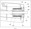
- the connecting member 44 includes a second sleeve 71 having a hollow cylindrical shape.
- the stator assembly 42 includes a stator coil provided on the second sleeve 71.
- the second sleeve 71 is sleeved on the reel 30 and has a gap with the reel 30.
- the reel 30 passes through the second sleeve 71 and extends, and the reel 30 can rotate freely.
- a bearing 51 is provided at an end of the reel 30 adjacent to an outer side of the outer rotor motor 41.
- the bearing 51 is provided in a bearing seat 52.
- the bearing seat 52 is fixedly connected to the second sleeve 71.
- the bearing seat 52 and the connecting member 44 may be integrally formed.
- the stator assembly 42 and the connecting member 44 as a whole can be assembled or disassembled from the reel 30 simultaneously.
- An inner wall of the outer rotor 43 is circumferentially inlaid with magnetic steel.
- An inner end of the outer rotor 43 extends axially to the reel 30.
- the outer rotor 43 forms an end cap on an inner side to prevent an internal component of the outer rotor motor 41 from being exposed.
- the reel 30 includes a large-diameter section 31 and a small-diameter section 32.
- a step 33 is formed between the large-diameter section 31 and the small-diameter section 32.
- the inner end of the outer rotor 43 extends axially to the step 33, so as to limit the outer rotor motor 41.
- a radial labyrinth seal is formed between the outer end of the connecting member 44 and the outer end of the outer rotor 43.
- the outer end of the outer rotor 43 extends radially to form a flange 47.
- An outer end surface of the flange 47 is provided with two annular notches 48.
- An outer end of the connecting member 44 extends to the flange 47.
- An end surface of the connecting member 44 facing the flange 47 is correspondingly provided with two annular lug bosses 49. The two lug bosses 49 are inserted into the two notches 48 to form the radial labyrinth seal between the outer end of the connecting member 44 and the outer end of the outer rotor 43.
- notch 48 there may be one or more than one notch 48 and lug boss 49, which is not limited herein.
- the lug boss 49 may also be provided on the flange 47, and correspondingly, the notch 48 may be provided on the connecting member 44, provided that the radial labyrinth seal can be formed between the outer end of the connecting member 44 and the outer end of the outer rotor 43.
- two ends of the reel 30 can be supported by a bearing assembly.
- the reel 30, the support plates 21, the blades 20 and the outer rotor 43 rotate synchronously.
- the stator assembly 42 is fixed to the frame through the connecting member 44 to keep still, and the outer rotor 43 drives the blades 20 to rotate.
- the direct drive of the built-in outer rotor motor avoids the efficiency loss of the related transmission mechanism, greatly improves the working efficiency of the cylinder cutter, greatly reduces the noise of the whole machine, and realizes a compact structure.
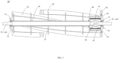
- the connecting member 44 is a motor shaft 70
- the reel 30 is shaped as a hollow straight cylinder.
- the reel 30 may also be set as a hollow variable-diameter cylinder if necessary.
- the motor shaft 70 passes through the reel 30, and two ends of the motor shaft 70 extend out of the reel.
- the stator assembly 42 is directly circumferentially limited on the motor shaft 70 through a key 46.
- the two ends of the motor shaft 70 are provided with flat positions, and the motor shaft is fixedly connected to a frame through the flat positions.
- Bearings 51 are further provided at the two ends of the motor shaft 70, and the bearings 51 are respectively provided in bearing seats 52.
- a bearing seat 52 at an end adjacent to one end of the outer rotor motor 41 is integrally formed with the outer rotor 43, and a bearing seat 52 at an end far away from the outer rotor motor 41 is fixedly connected to the reel 30.
- the outer rotor 43 is fixedly connected to the support plate 21 at an end of the motor compartment 40 by a fixing bolt 50.
- the outer rotor 43 and the bearing seat 52 integrally formed there-with are adapted to the shape of the motor compartment 40, and the bearing seat 52 at the other end is adapted to the shape of the reel 30 to ensure that the overall structure is concentric.
- the motor shaft 70 is fixed to the frame by the flat positions at both ends, and the stator assembly 42 is fixed to the motor shaft 70 by the key 46 and remains stationary.
- the outer rotor 43 is fixedly connected to the support plate 21 by a fixing bolt 50, such that the cylinder cutter is driven to rotate by the outer rotor of the motor.
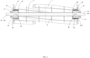
- FIG. 4 shows a major structure of a mowing cylinder cutter driven by a built-in outer rotor motor according to a third embodiment of the present invention.
- the mowing cylinder cutter 10 driven by a built-in outer rotor motor includes blades 20 and a reel 30.
- the blades 20 are multiple and spiral.
- Motor compartments 40 are provided at two ends of the reel 30.
- the blades 20 are fixedly connected to the reel 30 and the motor compartments 40 through a plurality of support plates 21 respectively.
- An outer rotor motor 41 is provided in each of the motor compartments 40.
- the outer rotor motor 41 includes a stator assembly 42 and an outer rotor 43.
- the stator assembly 42 is connected to a frame through the connecting member 44.
- the outer rotor 43 is fixedly connected to the support plate 21 on the motor compartment 40 and further fixedly connected to the reel 30.
- the connecting member 44 is a motor shaft 70
- the reel 30 is shaped as a hollow straight cylinder.
- the reel 30 may also be set as a hollow variable-diameter cylinder if necessary.
- the motor shaft 70 passes through the reel 30, and two ends of the motor shaft 70 extend out of the reel.
- the two ends of the motor shaft 70 are provided with flat positions, and the motor shaft 70 is fixed to a frame through the flat positions.
- the stator assembly 42 includes a first sleeve 421 and a stator coil 422.
- the stator coil 422 is provided on the first sleeve 421.
- the first sleeve 421 is provided on the motor shaft 70 and is circumferentially limited through a key 46 to keep still during use.
- the stator assembly 42 and the motor shaft 70 as a whole can be assembled or disassembled from the reel 30 simultaneously.
- the outer rotor 43 is fixed to the support plate 21 at an end adjacent to the motor compartment 40 by a fixing bolt 50.
- two outer rotor motors are arranged symmetrically on two sides of the cylinder cutter, which minimizes the influence of the built-in motors on the discharging of grass and realizes the power distribution between the two ends.
- this design is more compact than the one-sided design of motor.
- FIG. 5 shows a major structure of the lawn care tool driven by a built-in outer rotor motor.
- the lawn care tool 90 driven by a built-in outer rotor motor provided by this embodiment includes a working part 80, a main shaft 60, a motor shaft 70 and an outer rotor motor 41.
- the main shaft 60 is shaped as a hollow cylinder.
- the motor shaft 70 passes through the main shaft 60, and two ends of the motor shaft 70 extend out of the main shaft.
- One end of the main shaft 60 is connected to the motor shaft 70 through a bearing assembly, and the outer rotor motor 41 is located in the main shaft 60 and adjacent to the other end of the main shaft 60.
- the working part 80 may be fixedly connected to the outer surface of the main shaft 60 through a key.
- the outer surface of the main shaft 60 is spline-shaped, and the working part 80 is fixedly connected to the outer surface of the main shaft 60 through a spline.
- the fixing method of the working part 80 to the outer surface of the main shaft 60 is not limited, as long as the working part can rotate with the main shaft 60 to perform a corresponding function.
- the working part 80 may be a root cutting blade or a grass grooming blade, as shown in FIGS. 6 and 7 , but the shapes of the root cutting blade and the grass grooming blade are not limited herein.
- the corresponding working part 80 may be replaced according to actual needs, and the specific function and structure of the working part 80 are not limited.
- the working part 80 may be fixedly connected to the outer surface of the main shaft 60 at an interval through a spacer sleeve 81, and a fixing sleeve 82 is provided at two ends of the main shaft 60 for firm locking.
- flat positions are provided at the two ends of the motor shaft 70, and the motor shaft 70 is circumferentially fixed to a frame through the flat positions.
- An outer end cap 45 of the outer rotor motor 41 is integrally formed with the outer rotor 43, and is fixed to the main shaft 60 by a screw 83, such that the outer rotor 43 can rotate synchronously with the main shaft 60.
- the motor shaft 70 and the stator assembly 42 remain stationary.
- the outer rotor 43 drives the root cutting blade or grass grooming blade or other lawn care working part on the main shaft 60 to rotate to complete root cutting or grass grooming or other lawn care work.
- bearing assembly in the above embodiment may be a combination of a bearing and a bearing seat, which is a conventional design, and will not be repeated here.
- the outer rotor motor may be an outer rotor brushless motor, which is not limited herein.
- the outer rotor motor is provided inside the cylinder cutter or the working part, and the cylinder cutter or the working part is driven to rotate through the outer rotor.
- the present invention achieves a compact structure and high transmission efficiency. This design avoids additional efficiency loss, and greatly improves the work efficiency.
- the direct drive of the outer rotor motor improves the working torque and can cope with a complex working environment.
Landscapes
- Life Sciences & Earth Sciences (AREA)
- Environmental Sciences (AREA)
- Engineering & Computer Science (AREA)
- Mechanical Engineering (AREA)
- Soil Sciences (AREA)
- Harvester Elements (AREA)
Claims (7)
- Dispositif de coupe en rouleau de tonte de gazon entraîné par un moteur à rotor externe intégré, dans lequel le dispositif de coupe en rouleau de tonte de gazon (10) comprend un moteur à rotor externe (41), des lames (20) et une bobine (30) ; le moteur à rotor externe comprend un ensemble stator (42) et un rotor externe (43) ; l'ensemble stator est relié à un cadre à travers un organe de liaison (44) ; et les pales sont multiples et en spirale ;
caractérisé en ce que les lames (20) sont reliées de manière fixe à la bobine (30) à travers une pluralité de plaques de support (21), de telle sorte qu'il y ait aucun contact entre la bobine (30) et les lames (20) ; au moins une extrémité de la bobine (30) est pourvue du moteur à rotor externe (41), de telle sorte que l'extrémité de la bobine (30) est entourée par le moteur à rotor externe (41) ; et le rotor externe (43) est relié de manière fixe à la bobine (30) et aux lames (20), de telle sorte que les lames (20) sont reliées de manière fixe à chacun du rotor externe (43) et de la bobine (30) simultanément. - Dispositif de coupe en rouleau de tonte de gazon entraîné par le moteur à rotor externe intégré selon la revendication 1, caractérisé en ce que l'organe de liaison est un arbre de moteur (70) ; la bobine est sous la forme d'un cylindre droit creux ou d'un cylindre de diamètre variable ; une extrémité ou deux extrémités de la bobine sont pourvues d'un compartiment de moteur (40) ; l'arbre de moteur passe à travers la bobine, et deux extrémités de l'arbre de moteur s'étendent hors de la bobine ; et les deux extrémités de l'arbre de moteur sont pourvues de positions plates, et l'arbre de moteur est relié de manière fixe au cadre par le moyen des positions plates.
- Dispositif de coupe en rouleau de tonte de gazon entraîné par le moteur à rotor externe intégré selon la revendication 2, caractérisé en ce qu'une extrémité de la bobine est pourvue du moteur à rotor externe et du compartiment de moteur ; le moteur à rotor externe est prévu dans le compartiment de moteur ; et l'ensemble stator est limité circonférentiellement à l'arbre de moteur par le moyen d'une clavette (46).
- Dispositif de coupe en rouleau de tonte de gazon entraîné par le moteur à rotor externe intégré selon la revendication 2, caractérisé en ce que deux extrémités de la bobine sont respectivement pourvues de moteurs à rotor externe (41) et de compartiments de moteur (40) ; deux moteurs à rotor externe sont respectivement prévus dans les compartiments de moteur correspondants ; l'ensemble stator comprend un premier manchon (421) et une armature de stator (422) ; l'armature de stator est prévue sur le premier manchon ; et le premier manchon est prévu sur l'arbre de moteur et est limité circonférentiellement par le moyen d'une clavette (46).
- Dispositif de coupe en rouleau de tonte de gazon entraîné par le moteur à rotor externe intégré selon la revendication 3 ou 4, caractérisé en ce que le compartiment de moteur fait partie de la bobine ; le compartiment de moteur est pourvu d'une ouverture tournée vers l'extérieur ; le moteur à rotor externe est prévu dans le compartiment de moteur à partir de l'ouverture ; un capuchon d'extrémité (45) est prévu sur un côté externe du moteur à rotor externe ; le capuchon d'extrémité est formé d'un seul tenant avec le rotor externe, et est mis en correspondance avec le compartiment de moteur pour sceller le moteur à rotor externe dans le compartiment de moteur ; un centre du capuchon d'extrémité est pourvu d'un palier (51) ; et l'arbre de moteur est relié à et passe à travers le palier.
- Dispositif de coupe en rouleau de tonte de gazon entraîné par le moteur à rotor externe intégré selon la revendication 1, caractérisé en ce qu'une extrémité ou deux extrémités de la bobine sont pourvues d'un moteur à rotor externe ; l'organe de liaison comprend un deuxième manchon (71) creux et cylindrique ; l'ensemble stator comprend une armature de stator (422) ; l'armature de stator est prévue sur le deuxième manchon de l'organe de liaison ; le deuxième manchon est emmanché sur la bobine et présente un jeu avec la bobine ; une extrémité externe du deuxième manchon et une extrémité du rotor externe forment un joint à labyrinthe radial ; une extrémité de la bobine adjacente à un côté externe du deuxième manchon est pourvue d'un palier (51) ; le palier est prévu dans un siège de palier (52) ; et le siège de palier est relié de manière fixe au deuxième manchon.
- Dispositif de coupe en rouleau de tonte de gazon entraîné par le moteur à rotor externe intégré selon la revendication 6, caractérisé en ce que le siège de palier et l'organe de liaison sont formés d'un seul tenant ; et/ouune extrémité interne du rotor externe s'étend axialement jusqu'à la bobine ; et/ou,une extrémité externe du rotor externe s'étend radialement pour former une bride (47) ; une surface d'extrémité externe de la bride est pourvue d'au moins une encoche annulaire (48) ; une extrémité externe de l'organe de liaison s'étend jusqu'à la bride ; une surface d'extrémité de l'organe de liaison tournée vers la bride est pourvue de manière correspondante avec au moins un bossage de patte annulaire (49) ; et le bossage de patte est inséré dans l'encoche, dans lequel l'extrémité externe de l'organe de liaison et l'extrémité externe du rotor externe forment le joint à labyrinthe radial.
Applications Claiming Priority (2)
| Application Number | Priority Date | Filing Date | Title |
|---|---|---|---|
| CN202011561964.5A CN112690084B (zh) | 2020-12-25 | 2020-12-25 | 内置外转子电机驱动的草坪修剪滚刀 |
| PCT/CN2021/075452 WO2022134282A1 (fr) | 2020-12-25 | 2021-02-05 | Dispositif de coupe en rouleau de tonte de gazon entraîné par un moteur à rotor externe intégré et outil d'entretien de gazon |
Publications (4)
| Publication Number | Publication Date |
|---|---|
| EP4260678A1 EP4260678A1 (fr) | 2023-10-18 |
| EP4260678A4 EP4260678A4 (fr) | 2024-06-12 |
| EP4260678C0 EP4260678C0 (fr) | 2025-01-08 |
| EP4260678B1 true EP4260678B1 (fr) | 2025-01-08 |
Family
ID=75510532
Family Applications (1)
| Application Number | Title | Priority Date | Filing Date |
|---|---|---|---|
| EP21908297.1A Active EP4260678B1 (fr) | 2020-12-25 | 2021-02-05 | Dispositif de coupe en rouleau de tonte de gazon entraîné par un moteur à rotor externe intégré et outil d'entretien de gazon |
Country Status (4)
| Country | Link |
|---|---|
| US (1) | US12256666B2 (fr) |
| EP (1) | EP4260678B1 (fr) |
| CN (1) | CN112690084B (fr) |
| WO (1) | WO2022134282A1 (fr) |
Families Citing this family (4)
| Publication number | Priority date | Publication date | Assignee | Title |
|---|---|---|---|---|
| IT202200006533A1 (it) * | 2022-04-01 | 2023-10-01 | Stiga S P A In Breve Anche St S P A | Dispositivo per la manutenzione di un terreno, segnatamente per il taglio di erba, e relativi metodi di fabbricazione e di funzionamento |
| CN116241554B (zh) * | 2023-02-28 | 2025-11-04 | 上海瑞宝造粒机有限公司 | 一种结构新型的杆端驱动轴承装置 |
| WO2024198258A1 (fr) * | 2023-03-31 | 2024-10-03 | 深圳森合创新科技有限公司 | Mécanisme de coupe et tondeuse intégrés à entraînement électrique |
| EP4449851A1 (fr) * | 2023-04-19 | 2024-10-23 | Tehnos d.o.o. | Rotor avec moteur électrique intégré pour une machine agricole et machine agricole avec ledit rotor |
Family Cites Families (29)
| Publication number | Priority date | Publication date | Assignee | Title |
|---|---|---|---|---|
| GB659967A (en) * | 1949-07-15 | 1951-10-31 | Edward Arthur Sewell | Improvements in lawn mowers |
| US2831308A (en) * | 1954-09-27 | 1958-04-22 | Andrew L Raba | Grass cutter |
| DE3921068A1 (de) * | 1989-06-28 | 1991-01-03 | Assche Victor Maria Van | Elektrisch betriebenen handrasenmaeher |
| US5305586A (en) * | 1992-08-20 | 1994-04-26 | Lundahl Research, Inc. | Crop processor |
| US7121073B2 (en) * | 2003-04-30 | 2006-10-17 | Deere & Company | Cutting reel adjusting system |
| ATE433802T1 (de) * | 2003-12-12 | 2009-07-15 | Wifag Maschf Ag | Aussenläuferantrieb |
| US7168227B2 (en) * | 2004-05-21 | 2007-01-30 | Textron Inc. | Internal combustion engine traction drive with electric cutting unit drive for walking greens mower |
| CN2812548Y (zh) * | 2005-07-26 | 2006-09-06 | 李友成 | 一种割草机滚刀装置 |
| US7677021B2 (en) * | 2007-07-26 | 2010-03-16 | Textrons Innovations Inc. | Replaceable reel blade system |
| CN101307772B (zh) * | 2008-06-09 | 2012-03-28 | 顿力集团有限公司 | 动密封防水外转子风机及防水方法 |
| JP5829794B2 (ja) * | 2010-01-13 | 2015-12-09 | 株式会社Ihi | 芝刈り車両 |
| JP2013123392A (ja) * | 2011-12-14 | 2013-06-24 | Makita Corp | 芝刈機 |
| CN203589902U (zh) * | 2013-12-05 | 2014-05-07 | 杭州雪尔电器有限公司 | 外转子电机 |
| CN103782679B (zh) * | 2014-02-28 | 2016-05-04 | 张志熙 | 一种多功能除草器械 |
| CN104079113B (zh) * | 2014-06-06 | 2016-06-08 | 浙江亚特电器有限公司 | 内嵌式外转子电机直驱割草机驱动轮及割草机 |
| CN204150992U (zh) * | 2014-10-24 | 2015-02-11 | 辽宁华禹重工有限公司 | 永磁卷扬机 |
| CN204518471U (zh) * | 2015-03-05 | 2015-08-05 | 淮安中绿园林机械制造有限公司 | 一种新型的滚刀剪草机的刀片间隙调节机构 |
| CN204653759U (zh) * | 2015-04-30 | 2015-09-23 | 云南昆船设计研究院 | 一种切丝机刀辊驱动装置 |
| CN206110070U (zh) * | 2015-11-30 | 2017-04-19 | 南京德朔实业有限公司 | 扫雪机 |
| WO2017123534A1 (fr) * | 2016-01-11 | 2017-07-20 | Therm-L-Tech Systems, LLC | Système intégré de moteur à entraînement direct |
| CN205666746U (zh) * | 2016-05-31 | 2016-10-26 | 珠海思达美科技有限公司 | 外转子无刷直流电机 |
| JP6552456B2 (ja) * | 2016-06-13 | 2019-07-31 | 本田技研工業株式会社 | 電動芝刈り機の制御装置 |
| CN108115302A (zh) * | 2017-12-19 | 2018-06-05 | 马鞍山市绿之友机械制造有限公司 | 一种剪草滚刀的加工方法 |
| CN207723718U (zh) * | 2017-12-19 | 2018-08-14 | 马鞍山市绿之友机械制造有限公司 | 一种剪草滚刀刀刃磨削装置 |
| CN208190486U (zh) * | 2018-05-15 | 2018-12-04 | 常州兰陵自动化设备有限公司 | 智能阀门电动装置用直流电机 |
| CN109362327B (zh) * | 2018-10-24 | 2024-04-16 | 浙江亚特电器股份有限公司 | 一种便于存放的割草机 |
| CN110063119B (zh) * | 2019-05-10 | 2022-05-03 | 四川一百发展科技有限公司 | 一种应用外转子电机的草坪修剪机 |
| JP7379011B2 (ja) * | 2019-08-09 | 2023-11-14 | ミネベアミツミ株式会社 | 回転機器 |
| CN210246534U (zh) * | 2019-09-25 | 2020-04-03 | 上海惠深工具科技有限公司 | 移轴式可变速外转子电机 |
-
2020
- 2020-12-25 CN CN202011561964.5A patent/CN112690084B/zh active Active
-
2021
- 2021-02-05 EP EP21908297.1A patent/EP4260678B1/fr active Active
- 2021-02-05 WO PCT/CN2021/075452 patent/WO2022134282A1/fr not_active Ceased
-
2022
- 2022-06-08 US US17/834,962 patent/US12256666B2/en active Active
Also Published As
| Publication number | Publication date |
|---|---|
| WO2022134282A1 (fr) | 2022-06-30 |
| US20220295700A1 (en) | 2022-09-22 |
| EP4260678A4 (fr) | 2024-06-12 |
| EP4260678C0 (fr) | 2025-01-08 |
| CN112690084B (zh) | 2022-08-26 |
| EP4260678A1 (fr) | 2023-10-18 |
| CN112690084A (zh) | 2021-04-23 |
| US12256666B2 (en) | 2025-03-25 |
Similar Documents
| Publication | Publication Date | Title |
|---|---|---|
| EP4260678B1 (fr) | Dispositif de coupe en rouleau de tonte de gazon entraîné par un moteur à rotor externe intégré et outil d'entretien de gazon | |
| EP3753396B1 (fr) | Élagueuse | |
| JP3957227B2 (ja) | 小型ガソリンエンジン動力式機器改装用万能型動力装置 | |
| EP4250541A3 (fr) | Support de stator de moteur sans balai à rotor externe | |
| US20100058726A1 (en) | Interchangeable electric motor for powered garden implements | |
| EP3152998B1 (fr) | Roue d'entraînement de tondeuse à gazon à entraînement direct de moteur électrique à rotor externe intégré et tondeuse à gazon | |
| CN114929009A (zh) | 用于割草机的电动马达和刀片组件 | |
| EP1510121B1 (fr) | Moteur électrique pour entraîner une tondeuse à lames rotatives | |
| JP6597996B2 (ja) | 移動体用モータユニット | |
| CN112166798A (zh) | 割草机 | |
| CN112690083A (zh) | 自走式轻型滚刀剪草机 | |
| CN214155402U (zh) | 内置外转子电机驱动的草坪修剪滚刀及草坪养护工具 | |
| US3932055A (en) | Vacuum turbine for a drill | |
| CN116616031A (zh) | 一种可拆接式锂电多功能打草机 | |
| US9964154B2 (en) | Drive arrangement for direct drive rotor | |
| CN116369034A (zh) | 一体式电驱动刀具及割草机 | |
| CN214155404U (zh) | 自走式轻型滚刀剪草机 | |
| CN217136082U (zh) | 切割装置及割草机 | |
| CN207476224U (zh) | 机器人割草机 | |
| CN213127128U (zh) | 一种割草机的刀盘驱动结构 | |
| CN223843654U (zh) | 带减速齿的割草电机 | |
| WO2024198258A1 (fr) | Mécanisme de coupe et tondeuse intégrés à entraînement électrique | |
| CN212116220U (zh) | 一种前置电机割草机 | |
| TWI797620B (zh) | 環形刀具及動力除草設備 | |
| EP4449851A1 (fr) | Rotor avec moteur électrique intégré pour une machine agricole et machine agricole avec ledit rotor |
Legal Events
| Date | Code | Title | Description |
|---|---|---|---|
| STAA | Information on the status of an ep patent application or granted ep patent |
Free format text: STATUS: THE INTERNATIONAL PUBLICATION HAS BEEN MADE |
|
| PUAI | Public reference made under article 153(3) epc to a published international application that has entered the european phase |
Free format text: ORIGINAL CODE: 0009012 |
|
| STAA | Information on the status of an ep patent application or granted ep patent |
Free format text: STATUS: REQUEST FOR EXAMINATION WAS MADE |
|
| 17P | Request for examination filed |
Effective date: 20230711 |
|
| AK | Designated contracting states |
Kind code of ref document: A1 Designated state(s): AL AT BE BG CH CY CZ DE DK EE ES FI FR GB GR HR HU IE IS IT LI LT LU LV MC MK MT NL NO PL PT RO RS SE SI SK SM TR |
|
| DAV | Request for validation of the european patent (deleted) | ||
| DAX | Request for extension of the european patent (deleted) | ||
| A4 | Supplementary search report drawn up and despatched |
Effective date: 20240515 |
|
| RIC1 | Information provided on ipc code assigned before grant |
Ipc: A01D 34/58 20060101ALI20240508BHEP Ipc: A01D 34/53 20060101AFI20240508BHEP |
|
| GRAP | Despatch of communication of intention to grant a patent |
Free format text: ORIGINAL CODE: EPIDOSNIGR1 |
|
| STAA | Information on the status of an ep patent application or granted ep patent |
Free format text: STATUS: GRANT OF PATENT IS INTENDED |
|
| INTG | Intention to grant announced |
Effective date: 20241018 |
|
| GRAS | Grant fee paid |
Free format text: ORIGINAL CODE: EPIDOSNIGR3 |
|
| GRAA | (expected) grant |
Free format text: ORIGINAL CODE: 0009210 |
|
| STAA | Information on the status of an ep patent application or granted ep patent |
Free format text: STATUS: THE PATENT HAS BEEN GRANTED |
|
| AK | Designated contracting states |
Kind code of ref document: B1 Designated state(s): AL AT BE BG CH CY CZ DE DK EE ES FI FR GB GR HR HU IE IS IT LI LT LU LV MC MK MT NL NO PL PT RO RS SE SI SK SM TR |
|
| REG | Reference to a national code |
Ref country code: GB Ref legal event code: FG4D |
|
| REG | Reference to a national code |
Ref country code: CH Ref legal event code: EP |
|
| REG | Reference to a national code |
Ref country code: DE Ref legal event code: R096 Ref document number: 602021024836 Country of ref document: DE |
|
| REG | Reference to a national code |
Ref country code: IE Ref legal event code: FG4D |
|
| U01 | Request for unitary effect filed |
Effective date: 20250123 |
|
| U07 | Unitary effect registered |
Designated state(s): AT BE BG DE DK EE FI FR IT LT LU LV MT NL PT RO SE SI Effective date: 20250130 |
|
| U20 | Renewal fee for the european patent with unitary effect paid |
Year of fee payment: 5 Effective date: 20250131 |
|
| PG25 | Lapsed in a contracting state [announced via postgrant information from national office to epo] |
Ref country code: RS Free format text: LAPSE BECAUSE OF FAILURE TO SUBMIT A TRANSLATION OF THE DESCRIPTION OR TO PAY THE FEE WITHIN THE PRESCRIBED TIME-LIMIT Effective date: 20250408 |
|
| PG25 | Lapsed in a contracting state [announced via postgrant information from national office to epo] |
Ref country code: PL Free format text: LAPSE BECAUSE OF FAILURE TO SUBMIT A TRANSLATION OF THE DESCRIPTION OR TO PAY THE FEE WITHIN THE PRESCRIBED TIME-LIMIT Effective date: 20250108 |
|
| PG25 | Lapsed in a contracting state [announced via postgrant information from national office to epo] |
Ref country code: ES Free format text: LAPSE BECAUSE OF FAILURE TO SUBMIT A TRANSLATION OF THE DESCRIPTION OR TO PAY THE FEE WITHIN THE PRESCRIBED TIME-LIMIT Effective date: 20250108 |
|
| PG25 | Lapsed in a contracting state [announced via postgrant information from national office to epo] |
Ref country code: NO Free format text: LAPSE BECAUSE OF FAILURE TO SUBMIT A TRANSLATION OF THE DESCRIPTION OR TO PAY THE FEE WITHIN THE PRESCRIBED TIME-LIMIT Effective date: 20250408 Ref country code: IS Free format text: LAPSE BECAUSE OF FAILURE TO SUBMIT A TRANSLATION OF THE DESCRIPTION OR TO PAY THE FEE WITHIN THE PRESCRIBED TIME-LIMIT Effective date: 20250508 |
|
| PG25 | Lapsed in a contracting state [announced via postgrant information from national office to epo] |
Ref country code: HR Free format text: LAPSE BECAUSE OF FAILURE TO SUBMIT A TRANSLATION OF THE DESCRIPTION OR TO PAY THE FEE WITHIN THE PRESCRIBED TIME-LIMIT Effective date: 20250108 |
|
| PG25 | Lapsed in a contracting state [announced via postgrant information from national office to epo] |
Ref country code: GR Free format text: LAPSE BECAUSE OF FAILURE TO SUBMIT A TRANSLATION OF THE DESCRIPTION OR TO PAY THE FEE WITHIN THE PRESCRIBED TIME-LIMIT Effective date: 20250409 |
|
| REG | Reference to a national code |
Ref country code: CH Ref legal event code: PL |
|
| PG25 | Lapsed in a contracting state [announced via postgrant information from national office to epo] |
Ref country code: SM Free format text: LAPSE BECAUSE OF FAILURE TO SUBMIT A TRANSLATION OF THE DESCRIPTION OR TO PAY THE FEE WITHIN THE PRESCRIBED TIME-LIMIT Effective date: 20250108 |
|
| PG25 | Lapsed in a contracting state [announced via postgrant information from national office to epo] |
Ref country code: MC Free format text: LAPSE BECAUSE OF FAILURE TO SUBMIT A TRANSLATION OF THE DESCRIPTION OR TO PAY THE FEE WITHIN THE PRESCRIBED TIME-LIMIT Effective date: 20250108 |
|
| PG25 | Lapsed in a contracting state [announced via postgrant information from national office to epo] |
Ref country code: CH Free format text: LAPSE BECAUSE OF NON-PAYMENT OF DUE FEES Effective date: 20250228 |
|
| PG25 | Lapsed in a contracting state [announced via postgrant information from national office to epo] |
Ref country code: CZ Free format text: LAPSE BECAUSE OF FAILURE TO SUBMIT A TRANSLATION OF THE DESCRIPTION OR TO PAY THE FEE WITHIN THE PRESCRIBED TIME-LIMIT Effective date: 20250108 |
|
| PG25 | Lapsed in a contracting state [announced via postgrant information from national office to epo] |
Ref country code: SK Free format text: LAPSE BECAUSE OF FAILURE TO SUBMIT A TRANSLATION OF THE DESCRIPTION OR TO PAY THE FEE WITHIN THE PRESCRIBED TIME-LIMIT Effective date: 20250108 |
|
| PLBE | No opposition filed within time limit |
Free format text: ORIGINAL CODE: 0009261 |
|
| STAA | Information on the status of an ep patent application or granted ep patent |
Free format text: STATUS: NO OPPOSITION FILED WITHIN TIME LIMIT |
|
| 26N | No opposition filed |
Effective date: 20251009 |
|
| PG25 | Lapsed in a contracting state [announced via postgrant information from national office to epo] |
Ref country code: IE Free format text: LAPSE BECAUSE OF NON-PAYMENT OF DUE FEES Effective date: 20250205 |
|
| U20 | Renewal fee for the european patent with unitary effect paid |
Year of fee payment: 6 Effective date: 20260119 |
|
| PGFP | Annual fee paid to national office [announced via postgrant information from national office to epo] |
Ref country code: GB Payment date: 20260120 Year of fee payment: 6 |