EP4260689A1 - Système pour installations de culture ou de recherche de plantes avec station interchangeable, récipients et ensemble de dispositifs de marquage pour ceux-ci - Google Patents
Système pour installations de culture ou de recherche de plantes avec station interchangeable, récipients et ensemble de dispositifs de marquage pour ceux-ci Download PDFInfo
- Publication number
- EP4260689A1 EP4260689A1 EP23167633.9A EP23167633A EP4260689A1 EP 4260689 A1 EP4260689 A1 EP 4260689A1 EP 23167633 A EP23167633 A EP 23167633A EP 4260689 A1 EP4260689 A1 EP 4260689A1
- Authority
- EP
- European Patent Office
- Prior art keywords
- container
- card
- changing station
- containers
- reading device
- Prior art date
- Legal status (The legal status is an assumption and is not a legal conclusion. Google has not performed a legal analysis and makes no representation as to the accuracy of the status listed.)
- Pending
Links
Images


Classifications
-
- A—HUMAN NECESSITIES
- A01—AGRICULTURE; FORESTRY; ANIMAL HUSBANDRY; HUNTING; TRAPPING; FISHING
- A01K—ANIMAL HUSBANDRY; AVICULTURE; APICULTURE; PISCICULTURE; FISHING; REARING OR BREEDING ANIMALS, NOT OTHERWISE PROVIDED FOR; NEW BREEDS OF ANIMALS
- A01K1/00—Housing animals; Equipment therefor
- A01K1/02—Pigsties; Dog-kennels; Rabbit-hutches or the like
- A01K1/03—Housing for domestic or laboratory animals
- A01K1/031—Cages for laboratory animals; Cages for measuring metabolism of animals
-
- G—PHYSICS
- G06—COMPUTING OR CALCULATING; COUNTING
- G06Q—INFORMATION AND COMMUNICATION TECHNOLOGY [ICT] SPECIALLY ADAPTED FOR ADMINISTRATIVE, COMMERCIAL, FINANCIAL, MANAGERIAL OR SUPERVISORY PURPOSES; SYSTEMS OR METHODS SPECIALLY ADAPTED FOR ADMINISTRATIVE, COMMERCIAL, FINANCIAL, MANAGERIAL OR SUPERVISORY PURPOSES, NOT OTHERWISE PROVIDED FOR
- G06Q10/00—Administration; Management
- G06Q10/08—Logistics, e.g. warehousing, loading or distribution; Inventory or stock management
- G06Q10/087—Inventory or stock management, e.g. order filling, procurement or balancing against orders
- G06Q10/0872—Inventory or stock management, e.g. order filling, procurement or balancing against orders using inventory planning
- G06Q10/08724—Inventory or stock management, e.g. order filling, procurement or balancing against orders using inventory planning by shelf level inventory management, e.g. planograms
Definitions
- the invention also relates to a corresponding shelf and such a changing station for animal breeding or plant research facilities, an associated container for the above system for animal breeding or plant research facilities for use in a changing station and a set of container marking devices for attachment to the above container and for use in a system for animal breeding or plant research facilities.
- a system for animal breeding or plant research facilities including management software shows and describes the WO 2011 / 124 209 A1 . It describes a method for process tracking of processes and/or services that relate to at least one object, in which a reading device records data from a container card assigned to the object or its container, the data describing the object or its properties. After identifying the object by recording the data of the container card by the reading device, a process or a service and/or the resulting, changed or possibly unchanged data of the object or its properties is recorded. Furthermore, a device and a computer system for carrying out the method as well as a computer program product for setting up such a computer system and a corresponding changing station for it are described.
- the WO 2014/053 436 A1 relates to a comparable device, in particular for an animal room facility or a plant laboratory facility with a shelf, with containers that contain examination objects, with a device for detecting the containers on the shelf and with a computing unit for storing and processing data.
- the organization of one or more objects can involve process tracking of processes and/or services that affect at least one object and/or the determination of the presence of an object, whereby the container itself can also be the object.
- the organization of the object can therefore occur indirectly via the organization of its container.
- the EP 2 627 169 B1 First and second identifiers can be seen on a cage for containing rodents, which are detected by a first and a second detector through a lid of the cage when the cage is inserted into a rail system of a shelf.
- the EP 2 950 637 B1 proposes the placement of RFiD chips in container lids of animal housing cages for short-distance reading on a shelf to accommodate a variety of animal housing cages.
- the object of the invention is to make the processing of container contents in animal breeding or plant research facilities less error-prone.
- the ergonomic concerns of the staff working in the breeding or research facility should also be given greater consideration.
- This task is solved in the above system for animal breeding or plant research facilities in that there is a machine-readable, different from the container card and non-autoclavable container card label on the containers for identifying (at least) the respective container card and thus the container and a corresponding one the reader includes various reading devices for detecting the container card labels.
- the autoclavable containers are used to hold an object that is being examined and worked with in the respective animal breeding or plant research facility.
- the container regularly consists of a container base or a container shell and a removable container lid.
- the object that is accommodated in the container shell can include one or more individuals, for example one or more animals, plants, seedlings or bacterial cultures.
- the containers are autoclaved after each use or before they are used again.
- the shelf or rack serves to store the containers in a space-saving manner as long as they are not being processed. It can also take on functions of supplying and/or disposing of the container contents.
- the changing station or the medical or microbiological safety workbench can be equipped with a system for generating a so-called laminar flow.
- a class II microbiological safety cabinet it has a hygiene area shielded from the rest of the room by air curtains so that the organisms do not come into contact with the room air when the containers are opened.
- the air curtain acts as a barrier and allows unhindered work with the containers and organisms.
- a class III microbiological safety workbench it is completely closed and has permanently installed gloves and locks through which tools and work materials are introduced.
- the management software for the objects serves to record them and to record activities on the objects, processes of the objects as well as the recording of the respective results, in particular changes to the examined objects and the provision of the respective data.
- the management software is located on a computer unit of the system. It contains data sets that concern the objects, examination processes, (interim) results, data of the personnel involved, etc. and the associated containers. At least some of the data sets are also located on the container cards described below.
- the computer unit communicates with the reader of the changing station, which reads the electronic container cards as soon as a container card is removed from the container and brought into the reading area of the reader or the mobile reader is directed at the container card.
- the reading device can not only capture data from the container card unidirectionally, for example reading it as a scanner, but also send it and thus have a bidirectional effect. For convenience, below is Nevertheless, we only talk about a reading device, even if it works bidirectionally, for example together with an RFID transponder.
- the electronic container card can be removed from the container because it contains electronics for displaying, sending and receiving data, which may not survive autoclaving together with the containers.
- the container card not only identifies the container to which it is attached, but also displays at least part of the data on the container contents directly on the container itself, thus enabling quick orientation of the staff of the breeding or research facility.
- the system comprises, on the one hand, at least one machine-readable container card label, different from the container card, which is attached or can be attached to the containers. It is assigned to the known container card and can therefore be recorded and clearly assigned to the associated container card separately and independently of the container card, even if they are spatially separated from one another.
- the container card label according to the invention can therefore serve to identify the respective container card and also, independently of it, to identify the container to which the associated container card and the container card label are attached.
- the system includes a reading device which corresponds to the container card label and is different from the known reading device for automatically detecting container card labels. For example, in order to achieve greater flexibility in positioning the reading device, a container can also have more than just one container card label.
- the reading device can also work unidirectionally or bidirectionally, depending on the equipment of the container card label.
- the container card is regularly read by machine by pointing a reading device at the container card or by positioning the container card, regularly together with the container, in the reading area of a reading device.
- the machine reading of the container card therefore requires a separate handling step by the staff of the breeding or research facility.
- the container card label is intended to be automatically detected by the associated reading device according to the invention. No personal action on the part of the staff is required for the machine recording of the container card label according to the invention.
- This makes the work of the staff much easier because the detection of a container no longer has to be carried out separately and manually, but preferably during the usual handling of the containers without disturbing or at least interrupting the workflow done yourself.
- the relief can also be seen in the fact that containers can no longer be mixed up and no manual intermediate notations of data or remote recordings of the containers have to be made, which requires long walking distances.
- the invention avoids a contamination bridge between the reading device and the container.
- the automatic recording must be reliable and safe to handle, but on the other hand it must not lead to incorrect recordings, for example mix-ups or double recording of containers. If several containers are present at the same time, the relevant container must be reliably and exclusively recorded in the corresponding position in the changing station or on the shelf. In particular, in order to exclude confusion, the reading device therefore preferably detects the container card label over only a short distance. For example, RFiD technology, especially NFC technology, or optical machine-readable codes are suitable for this.
- the reading device according to the invention can advantageously also be integrated into the regular workflow with regard to its spatial arrangement.
- the reading device can therefore be arranged at the changing station and there preferably on or in the area of its work surface. Manipulations of the container objects are regularly carried out at the changing station and observations, evaluations and reports are recorded, carried out and generated there. With the arrangement of the reading device in close spatial relation to the changing station or its work area, the reading device is literally located at the place where the breeding or research facility is happening.
- the reading device there can detect the container card label of the container and signal the presence of the container in the changing station to the management software.
- the reading device can signal to the management software that or as soon as the container or the container card label has left the reading area of the reading device and thus the work surface or the changing station.
- the software can ensure, for example, that manipulations to the container's data record can only be carried out in the meantime, i.e. only while the container is present in the changing station. This makes it possible to reliably exclude accidental and incorrect changes to data records from actually uninvolved or unprocessed containers.
- the reading device according to the invention can be arranged on the shelf and there at the respective storage location of a container.
- an action on the container can be automatically signaled as finally completed.
- recording the containers on the shelf makes inventory easier. If the shelf's reading device removes the container, it can be released in the management software to process its data.
- each container can be completely monitored because it can be detected at its two regular locations and the time for its stay in between can be greatly limited. For example, if a container is not detected by a reading device on the shelf or by a reading device at a changing station for a predetermined period of time, an error or warning message can be issued.
- the container card label can be attached to the container at any location as long as the reading device can reliably detect it there.
- the container card label can be arranged, for example, on the bottom or at least in the bottom area of the container.
- the reading device corresponding to the label in the changing station can then be arranged in or under the work surface and/or in the shelf under the storage area of the container or under the bottom surface of the container placed on the shelf.
- the container card label can alternatively be attached, for example, to a rear wall of the container so that it can be detected by a reading device on a rear side of the container's location on the shelf.
- the corresponding reading device can be arranged on the back of the work surface opposite an operating side of the work surface, especially if the changing station is only operated from one side and therefore does not interfere with the reading device on the back.
- the container card label can also be attached to a lid of the container, which is removed to process the objects and is placed on the back of the work surface during this time. Together with removing and placing the lid of the container at the rear, the container card label can enter the reading area of the reading device.
- the reading device can be installed be attached to a top of the storage space of the container in order to detect the container card label on the lid of the container from there.
- the reading device of the shelf or the changing station can also be arranged in a lateral area of the container space or the work surface.
- the reading device can then be arranged on the corresponding side of the container location on the shelf. Since corresponding reading devices are also arranged on or on the work surface in the changing station on the side, i.e. on the right-hand side and/or left-hand side, it may be necessary, for reasons of unhindered workflow, to arrange two container label labels per container, namely also on the right-hand side and left-hand side. It may therefore be irrelevant whether the container is placed on the right or left of the work surface.
- the container card label according to the invention is assigned to the known container card and can therefore be clearly assigned to the associated container card even when spatially separated from one another. An assignment can be made, for example, using color marking.
- the container card on the one hand and the container card label of the same container on the other hand can have identical identification marks, in particular identical identification numbers.
- the identification marks can be recorded mechanically, unidirectionally, for example optically as a QR code and/or bidirectionally, for example electronically as an RFID code.
- the RFID transponder can be written to. It makes it possible, for example, to write warning signals to the RFID transponder during processing at the changing station. The next time the container is opened in the changing station, a warning message may appear on a screen in the changing station or a warning tone may sound.
- the mutual assignment of container card and container card label can thus be produced by machine.
- the container equipped according to the invention can therefore be identified without errors both via the container card and via the container card label. If the associated pair of container card and container card label are unintentionally separated from each other, the associated container card can be determined, for example, by scanning the QR code on the container card label and by "flashing" an LED in the container card.
- the container card label only has an optically detectable code, it does not contain any electronics of its own and can therefore be equipped to be autoclavable. However, the container card cannot be autoclaved due to its electronics.
- the container card label can in particular be designed to be non-destructively removable and reusable from the container. As soon as the container card has to be removed from the associated container, for example because the container is no longer used but is being autoclaved, the container card label can also be detached from the container and, for example, attached to its associated container card until it is next used for a new container. This means that the pairing of mutually assigned container cards and container card labels does not need to be broken down.
- the container card label can have, for example, a microsuction film or microsuction cup film on the assembly side, by means of which it can be attached to the container or the container card and can be removed therefrom. Since the container card label is removable and is therefore not autoclaved together with the container, it may also contain its own electronics.
- the task mentioned at the beginning is also solved with the above shelf for a system for animal breeding or plant research facilities.
- the shelf is used to hold containers, which are regularly equipped with an electronic container card for identifying and displaying at least the container contents.
- the shelf is equipped with a reading device for detecting container-side container card labels that are different from the container cards.
- a reading device is arranged for each storage space for a container on the shelf, which detects the container card label of a container placed on the storage space at a short distance.
- the detection of the container on the shelf can be linked to a corresponding signal to the system's management software about the presence of the container on the shelf and, if applicable, its position on the shelf. Alternatively or additionally, a previous action on the container can be automatically signaled as finally completed.
- the reading device can report a free parking space and, if necessary, also indicate the removed container as being processed.
- recording the containers on the shelf enables them to be inventory quickly and at any time.
- the reading device can be attached to almost any position at which it can detect a wall of the container or the container card label attached to it at a short distance.
- the container card label can be attached to any wall of the container, for example on the bottom, on a long side, on a back or on its lid. Even with a container card on the front, it may not be necessary to attach the container card label to the front of the container from which it is gripped to remove it from the shelf. Especially with other container labels that work with or without a container card on the front, the front side can also be suitable for attaching the container card label. For example, reusable, colored container card labels with or without a QR code can be used to signal cage conditions, for example "animal sick" or "container overfilled".
- external data sources can even be referenced, such as protocols, SoPs (Standard Operation Procedure), telephone numbers or email addresses of a responsible animal welfare officer, or the animal number of a sick animal in the container.
- SoPs Standard Operation Procedure
- the reusable container card label can offer an electronic recognition option for the container in conjunction with a reading device and a computer unit.
- the task mentioned at the beginning is also solved with the above changing station for a system for animal breeding or plant research facilities.
- the changing station is used to process objects in containers that are equipped with a known electronic container card.
- the changing station has a work surface for placing the containers and a reader for the electronic container cards.
- it also has a reading device in the changing station that is different from the reading device for detecting container card labels on the container side that are different from the container cards.
- the reading device in the changing station automatically records and reads a container card label as soon as the container is placed on the work surface of the changing station.
- the reading device therefore identifies the container based on the container card label, which means that the contents of the container are also known by linking the container card label to the container card.
- the identified container can thus be registered in the management software as being in the changing station and released for processing or changing its data without further intervention by the staff.
- the reading device can also register this and signal it to the management software, whereupon the management software For example, the container can be locked for further manipulation of the data in the management software.
- the reading device is used to automatically record the container card labels over a short distance.
- the detection therefore takes place largely unnoticed by the operating personnel of the changing station while the containers are being handled.
- the reading device is therefore preferably located in the area of the work surface of the changing station where the containers are already standing or are placed when the objects are being processed.
- the reading device can therefore preferably be arranged under or in the work surface in the changing station in order to detect a container card label from there over a short distance, preferably in the floor area or at the bottom of a container.
- the design of the changing station itself is largely irrelevant: In a simple case, it can be designed as an open and mobile device or as a stationary work table. For more sensitive examinations, it can be designed as a laminar flow station or as a completely closed changing station with air conditioning and a glove box, i.e. as an isolator.
- the changing station can therefore have an input medium in the area of the work surface with which the data of the data record of the container or in particular its contents can be changed.
- the input medium preferably a keyboard, can be operated from the work surface without forcing the staff to change location.
- a keyboard can be embedded in the work surface as an input medium, the keys of which are covered with a germ-proof film. Built flush into the work surface, the input medium does not hinder the manipulation of the containers.
- the input medium can preferably be combined with a largely arbitrary data display device on which the data to be processed and the data changes made can be seen.
- the data display device can display the input medium functionally, e.g. its button arrangement and assignment.
- the data display device can be arranged above the containers placed on the work surface and at head height of the staff.
- the data display device can be designed as a conventional monitor or screen.
- a tablet computer in a suitable holder can serve as a data display device, which can also be removed from the changing station as a mobile device and used for other activities, e.g. for a recurring container check or similar.
- the task mentioned at the beginning is also solved with the above container for the above system for animal breeding or plant research facilities or for the above shelf or for the above changing station.
- the container is autoclavable and equipped with a removable electronic container card.
- the container has a machine-readable container card label that is different from the container card. It has an option for assignment to the container card and is used to identify at least the respective container. If the container card label is firmly and permanently connected to the container, it is designed to be autoclavable.
- the container card label can be recorded and read using a reading device. It is therefore attached to the container in such a way that it can preferably be detected during the manipulation of the containers on the work surface of the changing station or when returning or removing them from the shelf.
- a container can also have two or more container card labels.
- a preferred arrangement of container card labels on the container is, in particular, this Floor area, because the corresponding reading device can then conveniently be mounted in or under the work surface of the changing station or under the installation level or the floor level of the container on the shelf.
- a non-autoclavable container card label may be detachably attached to the container.
- the container or the container card label can therefore comprise an attachment device for reversibly attaching the container card label to the container.
- the attachment device can enable or promote electrostatic charging and thereby attraction. Alternatively, it can be based on a micro-suction film.
- the task mentioned at the beginning is also achieved with the above set of a container card for attachment to a container and a reusable container card label for multiple attachment to a container to identify at least the associated container.
- the kit is suitable for use in particular in the above system for animal breeding or plant research facilities or for use in the above shelf or changing station or for attachment to the above container of the system, shelf or changing station.
- the container card and the container card label are assigned to one another, for which purpose they are each equipped with identical machine-readable identification marks.
- the container card is linked in the management software to a data record that represents a container contents or an object and the container that holds the object.
- the container marked according to the invention can be identified via the identification mark of the container card label. Because the identification mark of the container card label corresponds to that of the container card, it can be checked at any time from the container card label whether the correct container card is on the container, or a container card that has fallen off, for example, can be assigned to the correct container. Even without a container card, the respective data record of the associated container can be identified based on the container card label and its identification mark.
- the container card label can be autoclavable and can remain on the container even if it is autoclaved before a new use.
- the container card label can be designed to be removable from the container according to a further advantageous embodiment of the invention.
- the container card label can therefore comprise an attachment device for reversibly attaching the container card label to the container.
- the attachment device can enable or promote electrostatic charging and thereby attraction. Alternatively, it can be based on a micro-suction film.
- the container card label can be recorded mechanically over a short distance, for which purpose it interacts with a reading device on the shelf and/or in the changing station.
- the container card label can therefore have an RFID chip and/or a QR code and/or a comparable machine-readable identification mark.
- a layer structure of the container card label can therefore include a micro-suction adhesive layer, an RFID label, a layer with a QR code and a laminating film and possibly have at least one reinforcing layer, namely a reinforcing layer between the adhesive layer and the RFID label and / or a Reinforcement layer between the RFID tag and the layer with the QR code.
- the above-mentioned task is also achieved by using a container card label with a machine-readable identification mark in the system explained above for animal breeding or plant research facilities or for use in the above shelf or changing station by attaching it to the above container.
- a container card label with a machine-readable identification mark in the system explained above for animal breeding or plant research facilities or for use in the above shelf or changing station by attaching it to the above container.
- the container card label can be used to check at any time whether the correct container card is on the container. It therefore enables automatic testing of the electronic container card on the container lid with the lower part of the container in which the object is located, even in real time. It can also be used to assign a container card that has fallen off to the correct container. Even without a container card, the container card label and its identification tag can be used to identify the respective data record of the associated container.
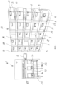
- Figure 1 shows, in a highly simplified form, an examination area of an animal breeding facility for keeping laboratory animals, namely a shelf 16 and a changing station 24, each of which is connected to a computer system, not shown.
- Staff at the animal breeding facility have direct access to the computer system.
- the shelf 16 is one of many largely similar ones to which the changing station 24 is assigned.
- the animal breeding facility houses animals as objects of containers, those in the form of cages 3.
- the cages 3 are stored in compartments 18 and stand on surfaces 19 of the shelf 16, which is in the Figure 1 simplified, it only includes 25 subjects 18.
- the changing station 24 also in the Figures 2 and 3 shown, comprises a table 20 with a work surface 10.
- a screen 6 is attached to the side of the changing station 24 as a display and input medium for the computer system (only Fig. 1 ).
- three opened cages 3a, 3b, 3c which come from the empty compartments 18 of the shelf 16, are placed on the work surface 10.
- the Figures 2, 3 3a, 3b, 3c show the cages 3a, 3b, 3c separately and closed laterally again, in particular to clarify the container card label 22 and its positioning.
- the staff usually carries out manipulations of the cages 3a, 3b, 3c or the animals on the work surface 10. They include processes of keeping, breeding and experiments and can, for example, relate to moving the animal F from the first cage 3a to the third cage 3c, examining the state of health or determining changes in the characteristics of the animals or medical procedures.
- the cages 3 can be used individually or simultaneously and in relation to each other (cf. Fig. 1 to 3 ) or processed serially without any mutual reference to one another.
- the staff of the animal breeding facility uses computer input to make the manipulations and their results part of data records in a database to which the computer system 2 has access or which it contains.
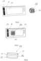
- Known electronic container cards 11 are removably attached to the cages 3a, 3b, 3c and are in the Figures 4, 5 are shown separately. They each contain a transmitting and a receiving device, for example RFID chip cards or RFID transponders, and also carry a machine-readable bar code 28 ( Fig. 4, 5 ). The code 28 is stored in the database and enables each container card 11 to be clearly identified.
- Identification data for the cages 3a, 3b, 3c and data on their contents or the objects they contain are stored on the container cards 11 and can be called up on a display 30.
- the container cards 11 allow the cages 3a, 3b, 3c or their contents to be clearly assigned to the stored data records in the database.
- the data sets characterize the respective contents of the cages 3a, 3b, 3c and reflect their contents and status.
- a bidirectionally acting reading device 17 of the changing station 20 communicates with the electronic container cards 11 via their respective transmitting and receiving device as soon as the container cards 11 are brought into a detection area of the reading device 17. This allows automatic updates of the displays of the container cards 11 to be carried out as soon as the container cards 11 come within the range of the reading device 17 of the changing station 20.
- the display 30 of the container cards 11 thus shows current data as quickly as possible as soon as the associated data record in the database has been changed.
- a container card label 22 is composed of four disk-shaped and surface-identical layers 32, 34, 36, 38: the cage side, in which Fig. 6
- the upper layer is a microsuction film or microsuction cup film 32.
- the next layer contains an NFC or other RFID chip 34, which can be detected by suitable reading devices at a short distance.
- the subsequent layer carries a machine-readable identification mark, namely a QR code 36, which is covered by the last layer, a transparent laminating film 38.
- the container card label 22 is so flat that it itself is attached to the bottom and outside of a bottom 23 of the cage 3, 3a, 3b, 3c ( Fig. 3 ) can be attached without affecting its handling.
- the micro suction cup film 32 is one of several options for attaching the container card label 22 to the cage 3a, 3b, 3c, for example in a way that can be removed without leaving any residue.
- the respective container card label 22 can be removed for cleaning purposes of the cages 3a, 3b, 3c. It can be attached to the associated container card 11 until its next use (cf. Fig. 5 ), thanks to the micro suction cup film 32, can be removed without leaving any residue.
- the QR code 36 is, possibly in addition to the RFID chip, a machine-readable and individual identification mark of the container card label 22.
- the container card label 22 attached to the cage 3a, 3b, 3c is therefore a physically independent and reusable device for identifying the cage 3a, 3b , 3c.
- Its QR code 36 corresponds to or is identical to the machine-readable code 28 of the associated container card 11, so that an association of the container card label 22 with the associated container card 11 (or vice versa) can be established mechanically, optically and quickly.
- the container card label 22 and the associated container card 11 therefore form a matching pair ( Fig. 4, 5 ), which can be identified in the database under the - functionally identical - respective codes, the QR code 36 or the barcode 28.
- FIG. 7 In the table 20 of the changing station 24 ( Fig. 1 to 3 ) are under the in Figure 7 Three bidirectional reading devices 7 are permanently installed on the work surface 10 shown separately, which only have a small detection range and can therefore only detect NFC or other RFID chips over a short distance.
- Each reading device 7 is attached in such a way that only one cage position or cage footprint on the work surface 10 is assigned to it, namely a left, a middle or a right position.
- the respective reading device 7 can only detect the respective cage 3a, 3b, 3c, which is equipped on its underside with a container card label 22 according to the invention and is in the respective position. It records the identification data of the container card label 22 closest to it.
- the left reading device 7, for example, only detects the container card label 22 of the cage 3a because those of the cages 3b, 3c are no longer in its detection range.
- the protection against confusion between the cages 3a, 3b, 3c can be achieved by using NFC transponders in the container card labels 22 and/or by using low-current reading devices 7, which have a reading distance of, for example, a maximum of 4 cm.
- the shelf 16 is also equipped with reading devices: one reading device 8 is assigned to a compartment 18 ( Fig. 1 ), in which they are under the installation surface 19 for one Cage 3 is attached - in the Figure 1 only shown for the rightmost compartments 18 of the shelf 16.
- the reading device 8 of this compartment 18 detects the container card label 22 of the cage 3 and thus identifies the cage 3.
- the reading device 8 registers the removal of the cage 3 as soon as the container card label 22 of the cage 3 is removed leaves the detection area.
- the reading devices 7, 8 are also connected to the computer system.
- a known animal management software or a known animal management system is stored in the computer system.
- the software processes in particular the signals from the reading devices 7, 8, for example the detection of a cage 3a, 3b, 3c on the work surface 10 in the changing station 24 or the removal from the shelf 16 or the return to the shelf 16.
- the computer system also offers Access to the data records that relate to the respective content or objects of the cages 3a, 3b, 3c and can manage them, in particular access, assign, change, update and make them available to authorized persons.
- the screen 6 is designed as a touch-sensitive or touchscreen screen and allows both the visualization of processes and services to be carried out using a graphical user interface as well as the input of commands and data in order to record processes carried out, services provided or examination results.
- a keyboard field 26 which is integrated into the work surface 10 of the changing station 24 as an additional input medium (esp. Fig. 7 ) to be able to make entries as quickly and blindly as possible with one hand.
- the keyboard field 26 includes 15 backlit keys, which are largely integrated into the plane of the work surface 10 under a silicone film, and offers good haptic resistance for working with gloves. Pressing several keys at the same time prevents a grid rising above the keys.
- the keyboard field 26 can be operated blindly. To help you quickly get used to blind operation of the keyboard field 26, the key assignments are also displayed on the screen 6.
- the screen 6 and the keyboard field 26 are therefore arranged ergonomically within sight and arm's reach at the changing station 24.
- the screen is located 6 - different from Figure 1 - Above the cages 3a, 3b, 3c at head height of the staff in the changing station 24.
- a tool bar (not shown) can be clamped between side walls of the changing station 24, to which the screen 6 is adjustable, for example via a so-called gooseneck.
- the toolbar also offers space for other equipment such as a scanner for reading animal ear tags or other markings or for the reader 17 or other such readers.
- the changing station 24 of the Figures 1 to 3 is shown as a so-called laminar flow station.
- the work surface 10 is therefore located within the laminar flow changing station 24 if high hygienic requirements are required.
- the table 20 can be designed as a cart to which the screen 6 is additionally attached.
- the table 20 then represents a mobile open changing station.
- the concept according to the invention can also be used in isolators: With the highest hygienic requirements, the shelf 16, the work surface 10 and, if necessary, the screen 6 of the changing station 24 are installed in an isolator that is operated using gloves.
- the computer system is placed outside the isolator because computer technology is very difficult to introduce into isolators and it is difficult to sterilize the computer system inside the isolator.
- data or other inputs from the changing station 24 equipped according to the invention can be entered within the isolator via the screen 6 and/or via a keyboard field of the isolator, which is strapped around an arm, for example, and operated through the transparent glove shaft.
- voice recognition can be provided to control the computer system with voice commands. It allows the activities in the changing station 24 to be documented without interrupting them.
- the reading devices 8 of the shelf 16 send a signal to the computer system, after which the cages 3a, 3b, 3c were removed from their compartments 18.
- the reading devices 7 transmit the identification data on the container card labels 22 of the cages 3a, 3b, 3c together with their respective positions on the work surface 10 ( Fig. 1 to 3 ) to the computer system.
- the computer system assigns the read identification data of the container card labels 22 to the respective data records from the database.
- the computer system therefore identifies the cage 3a or its contents, namely the test animals, in the left position of the work surface 10, the test animals in the cage 3b in the middle position and the empty cage 3c, for example, in the right position of the work surface 10. It thus records a concrete constellation of cages 3a, 3b, 3c.
- the cage 3 is considered "open", i.e. in progress.
- the previous, detailed examination area of an animal breeding facility is an exemplary embodiment, it can be modified in the usual way by the person skilled in the art to a wide extent without departing from the scope of the invention.
- the invention can also be used for plant research.
- the number of shelves, cages on the shelves and changing stations and the specific designs of the shelves, changing stations, cages, container cards, etc. can be done in a different form than that described here.
- the holders of the cages on the shelves or the work surface of the changing station can also be designed in a different shape if this is necessary for reasons of use or space or for design reasons.
- the use of the indefinite articles “a” or “an” does not exclude the fact that the features in question can also be present several times or more.
Landscapes
- Business, Economics & Management (AREA)
- Life Sciences & Earth Sciences (AREA)
- Environmental Sciences (AREA)
- Zoology (AREA)
- Economics (AREA)
- Engineering & Computer Science (AREA)
- Entrepreneurship & Innovation (AREA)
- Health & Medical Sciences (AREA)
- Marketing (AREA)
- Operations Research (AREA)
- Quality & Reliability (AREA)
- Strategic Management (AREA)
- Tourism & Hospitality (AREA)
- Physics & Mathematics (AREA)
- General Business, Economics & Management (AREA)
- General Physics & Mathematics (AREA)
- Theoretical Computer Science (AREA)
- Human Resources & Organizations (AREA)
- Development Economics (AREA)
- Animal Behavior & Ethology (AREA)
- Clinical Laboratory Science (AREA)
- General Health & Medical Sciences (AREA)
- Finance (AREA)
- Animal Husbandry (AREA)
- Biodiversity & Conservation Biology (AREA)
- Accounting & Taxation (AREA)
- Warehouses Or Storage Devices (AREA)
Applications Claiming Priority (1)
| Application Number | Priority Date | Filing Date | Title |
|---|---|---|---|
| DE102022109147 | 2022-04-13 |
Publications (1)
| Publication Number | Publication Date |
|---|---|
| EP4260689A1 true EP4260689A1 (fr) | 2023-10-18 |
Family
ID=86007286
Family Applications (1)
| Application Number | Title | Priority Date | Filing Date |
|---|---|---|---|
| EP23167633.9A Pending EP4260689A1 (fr) | 2022-04-13 | 2023-04-12 | Système pour installations de culture ou de recherche de plantes avec station interchangeable, récipients et ensemble de dispositifs de marquage pour ceux-ci |
Country Status (1)
| Country | Link |
|---|---|
| EP (1) | EP4260689A1 (fr) |
Cited By (1)
| Publication number | Priority date | Publication date | Assignee | Title |
|---|---|---|---|---|
| WO2025149169A1 (fr) * | 2024-01-12 | 2025-07-17 | Vusiongroup Sa | Système de détection mobile, pouvant être porté manuellement |
Citations (4)
| Publication number | Priority date | Publication date | Assignee | Title |
|---|---|---|---|---|
| WO2011124209A2 (fr) | 2010-04-06 | 2011-10-13 | Stephan Hammelbacher | Procédé, produit-programme d'ordinateur et station d'accueil pour suivi de processus |
| WO2014053436A1 (fr) | 2012-10-01 | 2014-04-10 | Stephan Hammelbacher | Procédé et dispositif pour l'organisation d'au moins un objet |
| EP2627169B1 (fr) | 2010-10-11 | 2019-12-18 | Innovive, Inc. | Procédé de surveillance de cages de confinement de rongeurs |
| EP2950637B1 (fr) | 2013-01-31 | 2021-01-13 | Tecniplast S.p.A. | Système et procédé de détection automatique de la présence de cages sur l'étagère d'une installation |
-
2023
- 2023-04-12 EP EP23167633.9A patent/EP4260689A1/fr active Pending
Patent Citations (4)
| Publication number | Priority date | Publication date | Assignee | Title |
|---|---|---|---|---|
| WO2011124209A2 (fr) | 2010-04-06 | 2011-10-13 | Stephan Hammelbacher | Procédé, produit-programme d'ordinateur et station d'accueil pour suivi de processus |
| EP2627169B1 (fr) | 2010-10-11 | 2019-12-18 | Innovive, Inc. | Procédé de surveillance de cages de confinement de rongeurs |
| WO2014053436A1 (fr) | 2012-10-01 | 2014-04-10 | Stephan Hammelbacher | Procédé et dispositif pour l'organisation d'au moins un objet |
| EP2950637B1 (fr) | 2013-01-31 | 2021-01-13 | Tecniplast S.p.A. | Système et procédé de détection automatique de la présence de cages sur l'étagère d'une installation |
Cited By (1)
| Publication number | Priority date | Publication date | Assignee | Title |
|---|---|---|---|---|
| WO2025149169A1 (fr) * | 2024-01-12 | 2025-07-17 | Vusiongroup Sa | Système de détection mobile, pouvant être porté manuellement |
Similar Documents
| Publication | Publication Date | Title |
|---|---|---|
| EP2287091B1 (fr) | Dispositif et réception d'objets devant être recyclés pour une salle d'opération | |
| AT413640B (de) | Verfahren zur entnahme einer probe aus einem system | |
| WO2011124209A2 (fr) | Procédé, produit-programme d'ordinateur et station d'accueil pour suivi de processus | |
| EP2903422B1 (fr) | Procédé et dispositif pour l'organisation d'au moins un objet | |
| EP0630820B1 (fr) | Procédé et système pour la surveillance de la logistique de préparation des articles stérilisés | |
| DE19758633C2 (de) | Vorrichtung zur Entnahme von biologischen Proben | |
| DE69101370T2 (de) | Verfahren und gerät zum unzweideutigen und permamenten in zusammenhangzubringenden medizinischen behälter mit vorhandenem patienten. | |
| EP4036212A1 (fr) | Incubateur et procédé | |
| DE102009056269A1 (de) | Vorrichtung, Verfahren und System zum Rekonfigurieren von Gegenständen | |
| EP2581863A1 (fr) | Dispositif et procédé d'assemblage d'ensembles d'instruments | |
| EP4288516A1 (fr) | Incubateur, système et procédé | |
| EP3226918A1 (fr) | Système de traitement pour le nettoyage et/ou la désinfection d'appareils medicaux et procédé de fonctionnement | |
| DE202022103719U1 (de) | Autonomer mobiler Laborassistenzroboter für ein in vitro diagnostisches Labor | |
| EP4268119B1 (fr) | Port intelligent - dispositif de lecture/reconnaissance multifonctionnel dans un circuit de produit stérile | |
| EP4312862A1 (fr) | Dispositif de codage double pour codage de contenant interne et externe | |
| DE102011114612A1 (de) | Verfahren zur Abwicklung von Kanban-Aufträgen und RFID-Palettenbox | |
| DE102020120442A1 (de) | Verfahren und Vorrichtung zur Einlagerung von medizinischen Proben | |
| AT413791B (de) | Verfahren zur erstellung eines auftragsdatensatzes für eine zu analysierende probe | |
| DE102009008917A1 (de) | Verfahren zur Zurverfügungstellung und Wiederaufbereitung eines medizinischen Produkts, medizinisches Produkt sowie System zur Durchführung des Verfahrens | |
| EP4736891A2 (fr) | Procédé de stérilisation et de stockage stérile d'instruments médicaux | |
| DE102023131407A1 (de) | Unterstützung der Handhabung medizinischer Instrumente | |
| EP4705838A1 (fr) | Système de traitement de moyen d'emballage pharmaceutique, procédé de fonctionnement d'un tel système et dispositif de surveillance | |
| DE9421086U1 (de) | System zur Überwachung des Materialflusses bei der Aufbereitung von Sterilgut | |
| Yazid | Development of Automated Visual Tracking System for Surgical Instruments | |
| DE102007026480A1 (de) | Verfahren und Vorrichtung zur Kommissionierung von Waren |
Legal Events
| Date | Code | Title | Description |
|---|---|---|---|
| PUAI | Public reference made under article 153(3) epc to a published international application that has entered the european phase |
Free format text: ORIGINAL CODE: 0009012 |
|
| STAA | Information on the status of an ep patent application or granted ep patent |
Free format text: STATUS: THE APPLICATION HAS BEEN PUBLISHED |
|
| AK | Designated contracting states |
Kind code of ref document: A1 Designated state(s): AL AT BE BG CH CY CZ DE DK EE ES FI FR GB GR HR HU IE IS IT LI LT LU LV MC ME MK MT NL NO PL PT RO RS SE SI SK SM TR |
|
| STAA | Information on the status of an ep patent application or granted ep patent |
Free format text: STATUS: REQUEST FOR EXAMINATION WAS MADE |
|
| 17P | Request for examination filed |
Effective date: 20231227 |
|
| RBV | Designated contracting states (corrected) |
Designated state(s): AL AT BE BG CH CY CZ DE DK EE ES FI FR GB GR HR HU IE IS IT LI LT LU LV MC ME MK MT NL NO PL PT RO RS SE SI SK SM TR |
|
| STAA | Information on the status of an ep patent application or granted ep patent |
Free format text: STATUS: EXAMINATION IS IN PROGRESS |
|
| 17Q | First examination report despatched |
Effective date: 20240828 |
|
| GRAP | Despatch of communication of intention to grant a patent |
Free format text: ORIGINAL CODE: EPIDOSNIGR1 |
|
| STAA | Information on the status of an ep patent application or granted ep patent |
Free format text: STATUS: GRANT OF PATENT IS INTENDED |