EP4260792A1 - Steuerung und augenuntersuchungsvorrichtung damit - Google Patents
Steuerung und augenuntersuchungsvorrichtung damit Download PDFInfo
- Publication number
- EP4260792A1 EP4260792A1 EP23162134.3A EP23162134A EP4260792A1 EP 4260792 A1 EP4260792 A1 EP 4260792A1 EP 23162134 A EP23162134 A EP 23162134A EP 4260792 A1 EP4260792 A1 EP 4260792A1
- Authority
- EP
- European Patent Office
- Prior art keywords
- coupling part
- magnetic coupling
- area
- operation unit
- unit
- Prior art date
- Legal status (The legal status is an assumption and is not a legal conclusion. Google has not performed a legal analysis and makes no representation as to the accuracy of the status listed.)
- Pending
Links
Images



Classifications
-
- A—HUMAN NECESSITIES
- A61—MEDICAL OR VETERINARY SCIENCE; HYGIENE
- A61B—DIAGNOSIS; SURGERY; IDENTIFICATION
- A61B3/00—Apparatus for testing the eyes; Instruments for examining the eyes
- A61B3/0075—Apparatus for testing the eyes; Instruments for examining the eyes provided with adjusting devices, e.g. operated by control lever
-
- A—HUMAN NECESSITIES
- A61—MEDICAL OR VETERINARY SCIENCE; HYGIENE
- A61B—DIAGNOSIS; SURGERY; IDENTIFICATION
- A61B3/00—Apparatus for testing the eyes; Instruments for examining the eyes
- A61B3/0016—Operational features thereof
-
- A—HUMAN NECESSITIES
- A61—MEDICAL OR VETERINARY SCIENCE; HYGIENE
- A61B—DIAGNOSIS; SURGERY; IDENTIFICATION
- A61B3/00—Apparatus for testing the eyes; Instruments for examining the eyes
- A61B3/0016—Operational features thereof
- A61B3/0033—Operational features thereof characterised by user input arrangements
-
- A—HUMAN NECESSITIES
- A61—MEDICAL OR VETERINARY SCIENCE; HYGIENE
- A61B—DIAGNOSIS; SURGERY; IDENTIFICATION
- A61B3/00—Apparatus for testing the eyes; Instruments for examining the eyes
- A61B3/10—Objective types, i.e. instruments for examining the eyes independent of the patients' perceptions or reactions
- A61B3/14—Arrangements specially adapted for eye photography
- A61B3/15—Arrangements specially adapted for eye photography with means for aligning, spacing or blocking spurious reflection ; with means for relaxing
- A61B3/152—Arrangements specially adapted for eye photography with means for aligning, spacing or blocking spurious reflection ; with means for relaxing for aligning
-
- G—PHYSICS
- G05—CONTROLLING; REGULATING
- G05G—CONTROL DEVICES OR SYSTEMS INSOFAR AS CHARACTERISED BY MECHANICAL FEATURES ONLY
- G05G9/00—Manually-actuated control mechanisms provided with one single controlling member co-operating with two or more controlled members, e.g. selectively, simultaneously
- G05G9/02—Manually-actuated control mechanisms provided with one single controlling member co-operating with two or more controlled members, e.g. selectively, simultaneously the controlling member being movable in different independent ways, movement in each individual way actuating one controlled member only
- G05G9/04—Manually-actuated control mechanisms provided with one single controlling member co-operating with two or more controlled members, e.g. selectively, simultaneously the controlling member being movable in different independent ways, movement in each individual way actuating one controlled member only in which movement in two or more ways can occur simultaneously
- G05G9/047—Manually-actuated control mechanisms provided with one single controlling member co-operating with two or more controlled members, e.g. selectively, simultaneously the controlling member being movable in different independent ways, movement in each individual way actuating one controlled member only in which movement in two or more ways can occur simultaneously the controlling member being movable by hand about orthogonal axes, e.g. joysticks
-
- G—PHYSICS
- G08—SIGNALLING
- G08C—TRANSMISSION SYSTEMS FOR MEASURED VALUES, CONTROL OR SIMILAR SIGNALS
- G08C21/00—Systems for transmitting the position of an object with respect to a predetermined reference system, e.g. tele-autographic system
-
- A—HUMAN NECESSITIES
- A61—MEDICAL OR VETERINARY SCIENCE; HYGIENE
- A61B—DIAGNOSIS; SURGERY; IDENTIFICATION
- A61B3/00—Apparatus for testing the eyes; Instruments for examining the eyes
- A61B3/10—Objective types, i.e. instruments for examining the eyes independent of the patients' perceptions or reactions
-
- G—PHYSICS
- G05—CONTROLLING; REGULATING
- G05G—CONTROL DEVICES OR SYSTEMS INSOFAR AS CHARACTERISED BY MECHANICAL FEATURES ONLY
- G05G9/00—Manually-actuated control mechanisms provided with one single controlling member co-operating with two or more controlled members, e.g. selectively, simultaneously
- G05G9/02—Manually-actuated control mechanisms provided with one single controlling member co-operating with two or more controlled members, e.g. selectively, simultaneously the controlling member being movable in different independent ways, movement in each individual way actuating one controlled member only
- G05G9/04—Manually-actuated control mechanisms provided with one single controlling member co-operating with two or more controlled members, e.g. selectively, simultaneously the controlling member being movable in different independent ways, movement in each individual way actuating one controlled member only in which movement in two or more ways can occur simultaneously
- G05G9/047—Manually-actuated control mechanisms provided with one single controlling member co-operating with two or more controlled members, e.g. selectively, simultaneously the controlling member being movable in different independent ways, movement in each individual way actuating one controlled member only in which movement in two or more ways can occur simultaneously the controlling member being movable by hand about orthogonal axes, e.g. joysticks
- G05G2009/04703—Mounting of controlling member
- G05G2009/04714—Mounting of controlling member with orthogonal axes
- G05G2009/04718—Mounting of controlling member with orthogonal axes with cardan or gimbal type joint
-
- G—PHYSICS
- G05—CONTROLLING; REGULATING
- G05G—CONTROL DEVICES OR SYSTEMS INSOFAR AS CHARACTERISED BY MECHANICAL FEATURES ONLY
- G05G9/00—Manually-actuated control mechanisms provided with one single controlling member co-operating with two or more controlled members, e.g. selectively, simultaneously
- G05G9/02—Manually-actuated control mechanisms provided with one single controlling member co-operating with two or more controlled members, e.g. selectively, simultaneously the controlling member being movable in different independent ways, movement in each individual way actuating one controlled member only
- G05G9/04—Manually-actuated control mechanisms provided with one single controlling member co-operating with two or more controlled members, e.g. selectively, simultaneously the controlling member being movable in different independent ways, movement in each individual way actuating one controlled member only in which movement in two or more ways can occur simultaneously
- G05G9/047—Manually-actuated control mechanisms provided with one single controlling member co-operating with two or more controlled members, e.g. selectively, simultaneously the controlling member being movable in different independent ways, movement in each individual way actuating one controlled member only in which movement in two or more ways can occur simultaneously the controlling member being movable by hand about orthogonal axes, e.g. joysticks
- G05G2009/0474—Manually-actuated control mechanisms provided with one single controlling member co-operating with two or more controlled members, e.g. selectively, simultaneously the controlling member being movable in different independent ways, movement in each individual way actuating one controlled member only in which movement in two or more ways can occur simultaneously the controlling member being movable by hand about orthogonal axes, e.g. joysticks characterised by means converting mechanical movement into electric signals
- G05G2009/04748—Position sensor for rotary movement, e.g. potentiometer
-
- G—PHYSICS
- G05—CONTROLLING; REGULATING
- G05G—CONTROL DEVICES OR SYSTEMS INSOFAR AS CHARACTERISED BY MECHANICAL FEATURES ONLY
- G05G9/00—Manually-actuated control mechanisms provided with one single controlling member co-operating with two or more controlled members, e.g. selectively, simultaneously
- G05G9/02—Manually-actuated control mechanisms provided with one single controlling member co-operating with two or more controlled members, e.g. selectively, simultaneously the controlling member being movable in different independent ways, movement in each individual way actuating one controlled member only
- G05G9/04—Manually-actuated control mechanisms provided with one single controlling member co-operating with two or more controlled members, e.g. selectively, simultaneously the controlling member being movable in different independent ways, movement in each individual way actuating one controlled member only in which movement in two or more ways can occur simultaneously
- G05G9/047—Manually-actuated control mechanisms provided with one single controlling member co-operating with two or more controlled members, e.g. selectively, simultaneously the controlling member being movable in different independent ways, movement in each individual way actuating one controlled member only in which movement in two or more ways can occur simultaneously the controlling member being movable by hand about orthogonal axes, e.g. joysticks
- G05G2009/04774—Manually-actuated control mechanisms provided with one single controlling member co-operating with two or more controlled members, e.g. selectively, simultaneously the controlling member being movable in different independent ways, movement in each individual way actuating one controlled member only in which movement in two or more ways can occur simultaneously the controlling member being movable by hand about orthogonal axes, e.g. joysticks with additional switches or sensors on the handle
-
- G—PHYSICS
- G05—CONTROLLING; REGULATING
- G05G—CONTROL DEVICES OR SYSTEMS INSOFAR AS CHARACTERISED BY MECHANICAL FEATURES ONLY
- G05G9/00—Manually-actuated control mechanisms provided with one single controlling member co-operating with two or more controlled members, e.g. selectively, simultaneously
- G05G9/02—Manually-actuated control mechanisms provided with one single controlling member co-operating with two or more controlled members, e.g. selectively, simultaneously the controlling member being movable in different independent ways, movement in each individual way actuating one controlled member only
- G05G9/04—Manually-actuated control mechanisms provided with one single controlling member co-operating with two or more controlled members, e.g. selectively, simultaneously the controlling member being movable in different independent ways, movement in each individual way actuating one controlled member only in which movement in two or more ways can occur simultaneously
- G05G9/047—Manually-actuated control mechanisms provided with one single controlling member co-operating with two or more controlled members, e.g. selectively, simultaneously the controlling member being movable in different independent ways, movement in each individual way actuating one controlled member only in which movement in two or more ways can occur simultaneously the controlling member being movable by hand about orthogonal axes, e.g. joysticks
- G05G2009/04781—Manually-actuated control mechanisms provided with one single controlling member co-operating with two or more controlled members, e.g. selectively, simultaneously the controlling member being movable in different independent ways, movement in each individual way actuating one controlled member only in which movement in two or more ways can occur simultaneously the controlling member being movable by hand about orthogonal axes, e.g. joysticks with additional rotation of the controlling member
-
- G—PHYSICS
- G05—CONTROLLING; REGULATING
- G05G—CONTROL DEVICES OR SYSTEMS INSOFAR AS CHARACTERISED BY MECHANICAL FEATURES ONLY
- G05G5/00—Means for preventing, limiting or returning the movements of parts of a control mechanism, e.g. locking controlling member
- G05G5/05—Means for returning or tending to return controlling members to an inoperative or neutral position, e.g. by providing return springs or resilient end-stops
Definitions
- the present disclosure relates to a controller, and more particularly, to a stick controller for adjusting the position of an examination unit with respect to an eye to be examined in an ophthalmic eye-examining device and an eye-examining device including the same.
- an eye-examining device fixes the face of an examinee at a predetermined position, adjusts the position of an examination unit with respect to the eye to be examined, aligns the eye to be examined with the examination unit, and then examines the eye to be examined using the examination unit.
- FIG. 1 is a view showing the configuration of a conventional eye-examining device.
- the conventional eye-examining device includes a base unit 10 having a headrest 12 for fixing the face of an examinee mounted thereto, an examination unit 14 that is mounted on the base unit 10 and moves forward and backward, left and right, and/or up and down with respect to the eye to be examined fixed to the headrest 12 and examines the eye to be examined, a drive unit (not shown) that is installed on the base unit 10 and moves the examination unit 14, and a controller 16 that moves the examination unit 14 to a desired position by controlling the drive unit.
- the drive unit may be a manual drive unit such as a gear that mechanically transmits the driving force of the controller 16 to the examination unit 14, or an electric drive unit that moves the examination unit 14 by electrically driving a motor according to a drive signal from the controller 16 (see Japanese Patent Application Publication No. 2014-23960 ).
- the position of the examination unit 14 can be precisely adjusted by a fine movement operation that drives the examination unit 14 at a slow speed, or the position of the examination unit 14 can be changed quickly by a coarse movement operation that drives the examination unit 14 at high speed.
- the position of the examination unit 14 can be changed quickly by a coarse movement operation that drives the examination unit 14 at high speed.
- 2014-23960 discloses a structure in which a coarse movement operation is performed when the tilt angle of the controller 16 is greater than a predetermined angle, and in this case, a restoring force is generated by using the elastic force of the spring so that the tilt angle of the controller 16 becomes equal to the predetermined angle.
- a restoring force is generated by using the elastic force of the spring so that the tilt angle of the controller 16 becomes equal to the predetermined angle.
- the tilt angle of the controller 16 is restored by the elastic force of the spring, it is difficult to accurately adjust the restoring force, and thus, there may arise problems of device failures, such as the magnitude of the restoring force being variable for each eye-examining device and the restoring force being decreased over time.
- a controller 20 comprising: an operation unit 22 configured to be operated by a user so as to be positioned in a first driving area or a second driving area; a first magnetic coupling part 30 coupled to the operation unit 22 and configured to move along a first area 34 together with the operation unit 22; a second magnetic coupling part 40 detachably coupled to the first magnetic coupling part 30 by magnetic force and configured to move along a second area 44; and a control signal generation unit 28 configured to output a first drive control signal when the operation unit 22 is positioned in the first driving area and output a second drive control signal when the operation unit 22 is positioned in the second driving area, wherein the first area 34 includes the second area 44 so that a movement area of the first magnetic coupling part 30 includes a movement area of the second magnetic coupling part 40, the first magnetic coupling part 30 and the second magnetic coupling part 40, while being coupled to each other by the magnetic force, move within the second area 44 according to driving of the operation unit 22 when the operation unit 22 is in
- an eye-examining device comprising: a base unit 10 having a headrest 12 for fixing the face of an examinee mounted thereto; an examination unit 14 mounted on the base unit 10 and configured to move in position with respect to an eye to be examined fixed to the headrest 12 and examine the eye to be examined; a drive unit installed on the base unit 10 and configured to move the examination unit 14; and the controller 20 described above configured to move the examination unit 14 to a desired position by controlling the drive unit.
- the magnitude of the restoring force for restoring to a predetermined position is uniform in each device when no external force is applied at a position out of the predetermined position, and the decrease of the restoring force over time is small. Further, the controller and the eye-examining device including the same in accordance with the present disclosure have an advantage that a mechanical structure for generating a restoring force is simple and easy to produce, and there are fewer occurrences of failures.
- FIG. 2 is an external perspective view of a controller in accordance with one embodiment of the present disclosure.
- the controller 20 in accordance with one embodiment of the present disclosure may generate a drive control signal for controlling a driving direction, a driving amount, and a driving speed of an examination unit 14 and drive the examination unit 14.
- the controller 20 in accordance with the present disclosure may include an operation unit 22, for example, a stick operation unit 22, and a control signal generation unit 28, and may further include a rotary dial 24, a measurement button 26, and the like, as needed.
- a user may drive the examination unit 14 by operating the operation unit 22 and the rotary dial 24.
- the examination unit 14 moves in the left and right R/L direction when the operation unit 22 is tilted in the left and right R/L direction, the examination unit 14 moves in the forward and backward F/B direction when the operation unit 22 is tilted in the forward and backward F/B direction, and the examination unit 14 moves in the up and down U/D direction when the rotary dial 24 is rotated in a clockwise or counterclockwise U/D direction.
- the measurement button 26 may be installed at the top of the operation unit 22, and examination, observation, and photographing operations of the examination unit 14 may be controlled using the measurement button 26.
- the control signal generation unit 28 detects the positions of the operation unit 22, the rotary dial 24, and so on, and generates a drive control signal that drives the examination unit 14 and the drive unit according to the positions of the operation unit 22 and the rotary dial 24.
- the control signal generation unit 28 may be a conventional sensor such as a potentiometer, an encoder, or the like that generates an electrical signal having a corresponding intensity according to the positions of the operation unit 22 and the rotary dial 24.
- the operation unit 22 can drive the examination unit 14 in two different methods.
- a fine movement operation of driving the examination unit 14 at a slow speed may be performed when the tilt angle x of the operation unit 22 is within a predetermined range (-a ⁇ x ⁇ +a), and a coarse movement operation of driving the examination unit 14 at high speed may be performed when the tilt angle x of the operation unit 22 is greater than the predetermined range (e.g., -b ⁇ x ⁇ -a and +a ⁇ x ⁇ +b, where a ⁇ b).
- the controller outputs signals corresponding to two different driving states according to the position of the operation unit 22, it is necessary to automatically switch from one driving state to the other.
- the operation unit 22 is kept in the coarse movement driving state by applying an external force to the operation unit 22, and when the external force applied to the operation unit 22 is removed, it is necessary for the tilt angle of the operation unit 22 to automatically return to the fine movement driving range so that the operation unit 22 is positioned in the fine movement driving state.
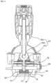
- FIG. 3 is a cross-sectional view showing the internal structure of a controller in accordance with one embodiment of the present disclosure.
- the controller in accordance with the present disclosure includes an operation unit 22, a first magnetic coupling part 30, a second magnetic coupling part 40, and a control signal generation unit 28.
- the operation unit 22 is operated by a user to be positioned in a first driving area or a second driving area.
- the control signal generation unit 28 of the controller outputs a first drive control signal when the operation unit 22 is positioned in the first driving area, and the control signal generation unit 28 of the controller outputs a second drive control signal when the operation unit 22 is positioned in the second driving area.
- FIG. 3 is a cross-sectional view showing the internal structure of a controller in accordance with one embodiment of the present disclosure.
- the controller in accordance with the present disclosure includes an operation unit 22, a first magnetic coupling part 30, a second magnetic coupling part 40, and a control signal generation unit 28.
- the operation unit 22 is operated by a user to be
- a fine movement control signal for driving the examination unit 14 at a slow speed may be outputted when the tilt angle x of the operation unit 22 is within a predetermined range (0 ⁇ x ⁇ +a, the second driving area) (A in FIG. 4 ), and a coarse movement control signal for driving the examination unit 14 at high speed may be outputted when the tilt angle x of the operation unit 22 is greater than the predetermined range (e.g., +a ⁇ x ⁇ +b, where a ⁇ b, the first driving area) (B in FIG. 4 ).
- the predetermined range e.g., +a ⁇ x ⁇ +b, where a ⁇ b, the first driving area
- the first magnetic coupling part 30 is coupled to the operation unit 22 and moves along a first area 34 together with the operation unit 22, and the second magnetic coupling part 40 is detachably coupled to the first magnetic coupling part 30 by magnetic force and moves along a second area 44.
- the first area 34 includes the second area 44 so that the movement area of the first magnetic coupling part 30 can include the movement area of the second magnetic coupling part 40.
- the second magnetic coupling part 40 moves within the second area 44 according to the driving of the operation unit 22 while being coupled to the first magnetic coupling part 30 by magnetic force when the operation unit 22 is in the second driving area, the first magnetic coupling part 30 moves to the first area 34 outside the second area 44 when the operation unit 22 is in the first driving area by applying an external force to the operation unit 22, the second magnetic coupling part 40 and the first magnetic coupling part 30 are separated from each other since the second magnetic coupling part 40 cannot move out of the second area 44, and an attractive force resulting from the magnetic force is generated between the second magnetic coupling part 40 and the first magnetic coupling part 30.
- the first magnetic coupling part 30 returns to the second area 44 by the attractive force between the second magnetic coupling part 40 and the first magnetic coupling part 30, and the operation unit 22 also returns to the second driving area.
- the first magnetic coupling part 30 and the second magnetic coupling part 40 may be magnetic bodies that are coupled to each other when no external force is applied, may be, for example, neodymium magnets, preferably circular magnets having the same outer diameter, but are not limited thereto, and a variety of combinations that can be detachably coupled by magnetic force, such as a metal-magnet, may be used.
- the first magnetic coupling part 30 and the second magnetic coupling part 40 may be housed inside a housing 50, the first area 34 where the first magnetic coupling part 30 moves may be formed by a first inner wall 32 inside the housing 50, and the second area 44 where the second magnetic coupling part 40 moves may be formed by a second inner wall 42 inside the housing 50.
- the first area 34 and the second area 44 are adjacent to each other so that the first magnetic coupling part 30 and the second magnetic coupling part 40 can be detachably coupled, and are formed such that the first area 34 includes the second area 44.
- the operation unit 22 may have various structures capable of moving the first magnetic coupling part 30 along the first area 34.
- the operation unit 22 may have a structure in which it rotates around a rotary shaft 22b, a handle 22a is formed at one end, a protrusion 22c that is slidably fitted into a fastening part 36 formed in the first magnetic coupling part 30 is formed at the other end, and a rotational motion that rotates the handle 22a with respect to the rotary shaft 22b induces a linear motion of the first magnetic coupling part 30 (see FIG. 4 ).
- FIGS. 4 and 5 are cross-sectional views showing a state in which a controller in accordance with one embodiment of the present disclosure is operated in two different methods and a state in which it is restored, respectively.
- the drawings at the bottom are plan views showing the positional relationship between the first magnetic coupling part 30, the second magnetic coupling part 40, the first area 34, and the second area 44.
- the first magnetic coupling part 30 and the second magnetic coupling part 40 are coupled to each other by magnetic force while being positioned in the second area 44, and the control signal generation unit 28 of the controller senses the position of the operation unit 22 and outputs a second drive control signal (e.g., a fine movement control signal).
- a second drive control signal e.g., a fine movement control signal
- the operation unit 22 when the operation unit 22 is caused to be positioned in the first driving area, for example, when the tilt angle x of the operation unit 22 is greater than the predetermined range (e.g., +a ⁇ x ⁇ + b, where a ⁇ b) by applying an external force to the operation unit 22 (B in FIG. 4 ), the first magnetic coupling part 30 is separated from the second magnetic coupling part 40 since the second magnetic coupling part 40 cannot move out of the second area 44 and is positioned in the first area 34 outside the second area 44, the control signal generation unit 28 of the controller senses the position of the operation unit 22 and outputs a first drive control signal (e.g., a coarse movement control signal).
- a first drive control signal e.g., a coarse movement control signal
- the first magnetic coupling part 30 returns to the second area 44 and couples with the second magnetic coupling part 40 by the attractive force between the first magnetic coupling part 30 and the second magnetic coupling part 40 (B in FIG. 5 ).
- the control signal generation unit 28 of the controller senses the position of the operation unit 22 and outputs a second drive control signal (e.g., a fine movement control signal). Therefore, when operating the operation unit 22, the operation unit 22 is restored to the position of 13.5 degrees if no external force is applied if the tilt angle x of the operation unit 22 is, for example, in the range of 13.5 degrees to 24.5 degrees.
- the ranges of the first driving area and the second driving area of the operation unit 22 can be readily changed by adjusting the sizes (areas) of the first area 34 and the second area 44 or adjusting the sizes of the first magnetic coupling part 30 and the second magnetic coupling part 40.
- an eye-examining device in accordance with the present disclosure includes a base unit 10 having a headrest 12 for fixing the face of an examinee mounted thereto, an examination unit 14 that is mounted on the base unit 10 and moves in position with respect to the eye to be examined fixed to the headrest 12 and examines the eye to be examined, a drive unit (not shown) that is installed on the base unit 10 and moves the examination unit 14, and the controller 20 described above as a device that moves the examination unit 14 to a desired position by controlling the drive unit, as shown in FIG. 1 .
- the present disclosure relates to an operating device (joystick module) that is restored in position from a position greater than or equal to a certain angle to a specific angle by utilizing an attractive force of two magnets pulling each other and a positional relationship between the two magnets. According to the present disclosure, since it can automatically move to another driving area if no separate external force is applied when the operation unit 22 is in a predetermined driving area, it is possible to prevent the examination unit 14 from being driven against the user's intention.
Landscapes
- Health & Medical Sciences (AREA)
- Life Sciences & Earth Sciences (AREA)
- Physics & Mathematics (AREA)
- Engineering & Computer Science (AREA)
- Biomedical Technology (AREA)
- General Health & Medical Sciences (AREA)
- Biophysics (AREA)
- Ophthalmology & Optometry (AREA)
- Veterinary Medicine (AREA)
- Heart & Thoracic Surgery (AREA)
- Medical Informatics (AREA)
- Molecular Biology (AREA)
- Surgery (AREA)
- Animal Behavior & Ethology (AREA)
- Public Health (AREA)
- General Physics & Mathematics (AREA)
- Automation & Control Theory (AREA)
- Eye Examination Apparatus (AREA)
Applications Claiming Priority (2)
| Application Number | Priority Date | Filing Date | Title |
|---|---|---|---|
| KR20220046824 | 2022-04-15 | ||
| KR1020220060806A KR102756266B1 (ko) | 2022-04-15 | 2022-05-18 | 컨트롤러 및 이를 포함하는 검안 장치 |
Publications (1)
| Publication Number | Publication Date |
|---|---|
| EP4260792A1 true EP4260792A1 (de) | 2023-10-18 |
Family
ID=85703599
Family Applications (1)
| Application Number | Title | Priority Date | Filing Date |
|---|---|---|---|
| EP23162134.3A Pending EP4260792A1 (de) | 2022-04-15 | 2023-03-15 | Steuerung und augenuntersuchungsvorrichtung damit |
Country Status (2)
| Country | Link |
|---|---|
| US (1) | US12551098B2 (de) |
| EP (1) | EP4260792A1 (de) |
Citations (5)
| Publication number | Priority date | Publication date | Assignee | Title |
|---|---|---|---|---|
| US4544803A (en) * | 1984-06-11 | 1985-10-01 | Ceramic Magnetics, Inc. | Positional transducer |
| US20090079939A1 (en) * | 2007-09-03 | 2009-03-26 | Nidek Co., Ltd. | Electric joystick mechanism for an ophthalmic apparatus |
| JP2014023960A (ja) | 2013-11-05 | 2014-02-06 | Canon Inc | 眼科装置 |
| CH709563A1 (de) * | 2014-04-25 | 2015-10-30 | Haag Ag Streit | Augenuntersuchungsgerät und Verfahren zu dessen Positionierung. |
| EP1046151B1 (de) * | 1998-11-04 | 2017-06-14 | Immersion Corporation | Kraftrückkopplungsvorrichtung mit betätigungvorrichtung mit beweglichem magnet |
Family Cites Families (22)
| Publication number | Priority date | Publication date | Assignee | Title |
|---|---|---|---|---|
| US3331972A (en) * | 1964-04-15 | 1967-07-18 | Bodenseewerk Perkin Elmer Co | Magnetic control stick system |
| DE1263347B (de) * | 1965-12-20 | 1968-03-14 | Haag Streit A G | Vorrichtung zur Feineinstellung optischer Instrumente |
| US4161726A (en) * | 1977-04-06 | 1979-07-17 | Texas Instruments Incorporated | Digital joystick control |
| CA1184624A (en) * | 1982-01-13 | 1985-03-26 | Yoshimitsu Ishitobi | Joystick controller using magnetosensitive elements with bias magnets |
| US4489303A (en) * | 1983-06-03 | 1984-12-18 | Advanced Control Systems | Contactless switch and joystick controller using Hall elements |
| JP3206937B2 (ja) * | 1991-07-31 | 2001-09-10 | 株式会社ニデック | 眼科装置用ジョイスティック機構 |
| JPH08185257A (ja) * | 1994-10-31 | 1996-07-16 | Matsushita Electric Ind Co Ltd | 座標入力装置 |
| US5675359A (en) * | 1995-01-13 | 1997-10-07 | Advanced Technology Systems, Inc. | Joystick controller |
| JP4121730B2 (ja) * | 2001-01-19 | 2008-07-23 | 富士通コンポーネント株式会社 | ポインティングデバイス及び携帯型情報機器 |
| ES1049932Y (es) * | 2001-08-21 | 2002-06-01 | Lorenzo Ind Sa | Organo de mando multidireccional. |
| JP2004326163A (ja) * | 2003-04-21 | 2004-11-18 | Alps Electric Co Ltd | ストークスイッチ |
| US20060267933A1 (en) * | 2005-05-25 | 2006-11-30 | Li Chong Tai | Eliminating mechanical spring with magnetic forces |
| JP2007004705A (ja) * | 2005-06-27 | 2007-01-11 | Mitsumi Electric Co Ltd | ジョイスティック装置 |
| DE102007002189B4 (de) * | 2006-10-31 | 2010-04-01 | Preh Gmbh | Drehsteller mit magnetisch erzeugter Haptik |
| US7695141B2 (en) * | 2008-03-13 | 2010-04-13 | Kowa Company Ltd. | Ocular light stimulus apparatus |
| US9870021B2 (en) * | 2009-04-15 | 2018-01-16 | SeeScan, Inc. | Magnetic manual user interface devices |
| JP5471393B2 (ja) * | 2009-12-11 | 2014-04-16 | 株式会社日本自動車部品総合研究所 | 入力装置 |
| JP5879684B2 (ja) | 2010-12-28 | 2016-03-08 | 株式会社ニデック | 視力計及び応答ユニット |
| JP5406868B2 (ja) * | 2011-02-28 | 2014-02-05 | キヤノン株式会社 | 眼科装置、眼科装置の制御方法及びプログラム |
| JP2015116402A (ja) * | 2013-12-19 | 2015-06-25 | キヤノン株式会社 | 眼科装置及びその制御方法 |
| DE102014001630B4 (de) * | 2014-02-07 | 2019-03-21 | Audi Ag | Bedienvorrichtung und Fahrzeug mit Bedienvorrichtung |
| US12013717B2 (en) * | 2020-04-03 | 2024-06-18 | Crouzet | Human-machine interface |
-
2023
- 2023-03-15 EP EP23162134.3A patent/EP4260792A1/de active Pending
- 2023-03-17 US US18/185,829 patent/US12551098B2/en active Active
Patent Citations (5)
| Publication number | Priority date | Publication date | Assignee | Title |
|---|---|---|---|---|
| US4544803A (en) * | 1984-06-11 | 1985-10-01 | Ceramic Magnetics, Inc. | Positional transducer |
| EP1046151B1 (de) * | 1998-11-04 | 2017-06-14 | Immersion Corporation | Kraftrückkopplungsvorrichtung mit betätigungvorrichtung mit beweglichem magnet |
| US20090079939A1 (en) * | 2007-09-03 | 2009-03-26 | Nidek Co., Ltd. | Electric joystick mechanism for an ophthalmic apparatus |
| JP2014023960A (ja) | 2013-11-05 | 2014-02-06 | Canon Inc | 眼科装置 |
| CH709563A1 (de) * | 2014-04-25 | 2015-10-30 | Haag Ag Streit | Augenuntersuchungsgerät und Verfahren zu dessen Positionierung. |
Also Published As
| Publication number | Publication date |
|---|---|
| US20230329546A1 (en) | 2023-10-19 |
| US12551098B2 (en) | 2026-02-17 |
Similar Documents
| Publication | Publication Date | Title |
|---|---|---|
| US5048529A (en) | Ultrasonic transducer probe | |
| AU3741395A (en) | Electromechanical positioning unit | |
| EP3011890A1 (de) | Einführungsvorrichtung | |
| AU2005263777B2 (en) | Geodesic measuring instrument with a piezo drive | |
| EP4331523A1 (de) | Eingabevorrichtung, hauptbetriebsvorrichtung und chirurgischer roboter | |
| EP2829217A1 (de) | Einsetzvorrichtung | |
| US7105984B2 (en) | Drive unit and an operating apparatus | |
| US20160121166A1 (en) | Training Apparatus | |
| US12551098B2 (en) | Controller and eye-examining device having the same | |
| KR100349212B1 (ko) | 차량탑재용 입력장치 | |
| US20200297436A1 (en) | Medical holding apparatus and medical observation system | |
| EP2849028A1 (de) | Bedienungselement | |
| JP7214489B2 (ja) | ステージ装置及び微小操作機器 | |
| KR102756266B1 (ko) | 컨트롤러 및 이를 포함하는 검안 장치 | |
| EP0891034B1 (de) | Einaxiger linear/rotierender Antrieb | |
| EP0989385A1 (de) | Kollimationsrichtungssteuerungsvorrichtung für Vermessungsinstrument | |
| CN109568094B (zh) | 一种眼睛训练仪及眼睛训练系统 | |
| JP2012045236A (ja) | 眼科装置 | |
| US6678565B2 (en) | Control unit | |
| KR20010053153A (ko) | 메커니컬 로크 기구 및 그 기구를 이용한 인젝터 헤드 | |
| CN116726418A (zh) | 一种机械手及控制方法 | |
| CN116898390A (zh) | 控制器及包括其的验眼装置 | |
| JP2506247B2 (ja) | マッサ―ジ機 | |
| Park et al. | Study on multi-DOF ultrasonic actuator for laparoscopic instrument | |
| JP3964273B2 (ja) | 3軸ロボット |
Legal Events
| Date | Code | Title | Description |
|---|---|---|---|
| PUAI | Public reference made under article 153(3) epc to a published international application that has entered the european phase |
Free format text: ORIGINAL CODE: 0009012 |
|
| STAA | Information on the status of an ep patent application or granted ep patent |
Free format text: STATUS: THE APPLICATION HAS BEEN PUBLISHED |
|
| AK | Designated contracting states |
Kind code of ref document: A1 Designated state(s): AL AT BE BG CH CY CZ DE DK EE ES FI FR GB GR HR HU IE IS IT LI LT LU LV MC ME MK MT NL NO PL PT RO RS SE SI SK SM TR |
|
| STAA | Information on the status of an ep patent application or granted ep patent |
Free format text: STATUS: REQUEST FOR EXAMINATION WAS MADE |
|
| 17P | Request for examination filed |
Effective date: 20240409 |
|
| RBV | Designated contracting states (corrected) |
Designated state(s): AL AT BE BG CH CY CZ DE DK EE ES FI FR GB GR HR HU IE IS IT LI LT LU LV MC ME MK MT NL NO PL PT RO RS SE SI SK SM TR |