EP4260899A1 - Hautpflegeanordnung - Google Patents
Hautpflegeanordnung Download PDFInfo
- Publication number
- EP4260899A1 EP4260899A1 EP22871709.6A EP22871709A EP4260899A1 EP 4260899 A1 EP4260899 A1 EP 4260899A1 EP 22871709 A EP22871709 A EP 22871709A EP 4260899 A1 EP4260899 A1 EP 4260899A1
- Authority
- EP
- European Patent Office
- Prior art keywords
- skin care
- cover
- component
- care assembly
- cold compress
- Prior art date
- Legal status (The legal status is an assumption and is not a legal conclusion. Google has not performed a legal analysis and makes no representation as to the accuracy of the status listed.)
- Granted
Links
Images


Classifications
-
- A—HUMAN NECESSITIES
- A61—MEDICAL OR VETERINARY SCIENCE; HYGIENE
- A61N—ELECTROTHERAPY; MAGNETOTHERAPY; RADIATION THERAPY; ULTRASOUND THERAPY
- A61N1/00—Electrotherapy; Circuits therefor
- A61N1/18—Applying electric currents by contact electrodes
- A61N1/32—Applying electric currents by contact electrodes alternating or intermittent currents
- A61N1/328—Applying electric currents by contact electrodes alternating or intermittent currents for improving the appearance of the skin, e.g. facial toning or wrinkle treatment
-
- A—HUMAN NECESSITIES
- A61—MEDICAL OR VETERINARY SCIENCE; HYGIENE
- A61F—FILTERS IMPLANTABLE INTO BLOOD VESSELS; PROSTHESES; DEVICES PROVIDING PATENCY TO, OR PREVENTING COLLAPSING OF, TUBULAR STRUCTURES OF THE BODY, e.g. STENTS; ORTHOPAEDIC, NURSING OR CONTRACEPTIVE DEVICES; FOMENTATION; TREATMENT OR PROTECTION OF EYES OR EARS; BANDAGES, DRESSINGS OR ABSORBENT PADS; FIRST-AID KITS
- A61F7/00—Heating or cooling appliances for medical or therapeutic treatment of the human body
- A61F7/007—Heating or cooling appliances for medical or therapeutic treatment of the human body characterised by electric heating
-
- A—HUMAN NECESSITIES
- A61—MEDICAL OR VETERINARY SCIENCE; HYGIENE
- A61N—ELECTROTHERAPY; MAGNETOTHERAPY; RADIATION THERAPY; ULTRASOUND THERAPY
- A61N1/00—Electrotherapy; Circuits therefor
- A61N1/02—Details
- A61N1/04—Electrodes
- A61N1/0404—Electrodes for external use
-
- A—HUMAN NECESSITIES
- A61—MEDICAL OR VETERINARY SCIENCE; HYGIENE
- A61B—DIAGNOSIS; SURGERY; IDENTIFICATION
- A61B18/00—Surgical instruments, devices or methods for transferring non-mechanical forms of energy to or from the body
- A61B18/18—Surgical instruments, devices or methods for transferring non-mechanical forms of energy to or from the body by applying electromagnetic radiation, e.g. microwaves
- A61B18/20—Surgical instruments, devices or methods for transferring non-mechanical forms of energy to or from the body by applying electromagnetic radiation, e.g. microwaves using laser
- A61B18/203—Surgical instruments, devices or methods for transferring non-mechanical forms of energy to or from the body by applying electromagnetic radiation, e.g. microwaves using laser applying laser energy to the outside of the body
-
- A—HUMAN NECESSITIES
- A61—MEDICAL OR VETERINARY SCIENCE; HYGIENE
- A61N—ELECTROTHERAPY; MAGNETOTHERAPY; RADIATION THERAPY; ULTRASOUND THERAPY
- A61N1/00—Electrotherapy; Circuits therefor
- A61N1/02—Details
- A61N1/04—Electrodes
- A61N1/0404—Electrodes for external use
- A61N1/0408—Use-related aspects
- A61N1/0452—Specially adapted for transcutaneous muscle stimulation [TMS]
-
- A—HUMAN NECESSITIES
- A61—MEDICAL OR VETERINARY SCIENCE; HYGIENE
- A61N—ELECTROTHERAPY; MAGNETOTHERAPY; RADIATION THERAPY; ULTRASOUND THERAPY
- A61N1/00—Electrotherapy; Circuits therefor
- A61N1/02—Details
- A61N1/04—Electrodes
- A61N1/0404—Electrodes for external use
- A61N1/0472—Structure-related aspects
- A61N1/0476—Array electrodes (including any electrode arrangement with more than one electrode for at least one of the polarities)
-
- A—HUMAN NECESSITIES
- A61—MEDICAL OR VETERINARY SCIENCE; HYGIENE
- A61N—ELECTROTHERAPY; MAGNETOTHERAPY; RADIATION THERAPY; ULTRASOUND THERAPY
- A61N1/00—Electrotherapy; Circuits therefor
- A61N1/02—Details
- A61N1/04—Electrodes
- A61N1/06—Electrodes for high-frequency therapy
-
- A—HUMAN NECESSITIES
- A61—MEDICAL OR VETERINARY SCIENCE; HYGIENE
- A61N—ELECTROTHERAPY; MAGNETOTHERAPY; RADIATION THERAPY; ULTRASOUND THERAPY
- A61N1/00—Electrotherapy; Circuits therefor
- A61N1/18—Applying electric currents by contact electrodes
-
- A—HUMAN NECESSITIES
- A61—MEDICAL OR VETERINARY SCIENCE; HYGIENE
- A61N—ELECTROTHERAPY; MAGNETOTHERAPY; RADIATION THERAPY; ULTRASOUND THERAPY
- A61N1/00—Electrotherapy; Circuits therefor
- A61N1/18—Applying electric currents by contact electrodes
- A61N1/32—Applying electric currents by contact electrodes alternating or intermittent currents
- A61N1/36—Applying electric currents by contact electrodes alternating or intermittent currents for stimulation
- A61N1/36014—External stimulators, e.g. with patch electrodes
-
- A—HUMAN NECESSITIES
- A61—MEDICAL OR VETERINARY SCIENCE; HYGIENE
- A61N—ELECTROTHERAPY; MAGNETOTHERAPY; RADIATION THERAPY; ULTRASOUND THERAPY
- A61N1/00—Electrotherapy; Circuits therefor
- A61N1/40—Applying electric fields by inductive or capacitive coupling ; Applying radio-frequency signals
-
- A—HUMAN NECESSITIES
- A61—MEDICAL OR VETERINARY SCIENCE; HYGIENE
- A61N—ELECTROTHERAPY; MAGNETOTHERAPY; RADIATION THERAPY; ULTRASOUND THERAPY
- A61N1/00—Electrotherapy; Circuits therefor
- A61N1/40—Applying electric fields by inductive or capacitive coupling ; Applying radio-frequency signals
- A61N1/403—Applying electric fields by inductive or capacitive coupling ; Applying radio-frequency signals for thermotherapy, e.g. hyperthermia
-
- A—HUMAN NECESSITIES
- A61—MEDICAL OR VETERINARY SCIENCE; HYGIENE
- A61N—ELECTROTHERAPY; MAGNETOTHERAPY; RADIATION THERAPY; ULTRASOUND THERAPY
- A61N5/00—Radiation therapy
- A61N5/06—Radiation therapy using light
- A61N5/0613—Apparatus adapted for a specific treatment
- A61N5/0616—Skin treatment other than tanning
- A61N5/0617—Hair treatment
-
- H—ELECTRICITY
- H05—ELECTRIC TECHNIQUES NOT OTHERWISE PROVIDED FOR
- H05K—PRINTED CIRCUITS; CASINGS OR CONSTRUCTIONAL DETAILS OF ELECTRIC APPARATUS; MANUFACTURE OF ASSEMBLAGES OF ELECTRICAL COMPONENTS
- H05K7/00—Constructional details common to different types of electric apparatus
- H05K7/20—Modifications to facilitate cooling, ventilating, or heating
- H05K7/2029—Modifications to facilitate cooling, ventilating, or heating using a liquid coolant with phase change in electronic enclosures
- H05K7/20336—Heat pipes, e.g. wicks or capillary pumps
-
- H—ELECTRICITY
- H05—ELECTRIC TECHNIQUES NOT OTHERWISE PROVIDED FOR
- H05K—PRINTED CIRCUITS; CASINGS OR CONSTRUCTIONAL DETAILS OF ELECTRIC APPARATUS; MANUFACTURE OF ASSEMBLAGES OF ELECTRICAL COMPONENTS
- H05K7/00—Constructional details common to different types of electric apparatus
- H05K7/20—Modifications to facilitate cooling, ventilating, or heating
- H05K7/2039—Modifications to facilitate cooling, ventilating, or heating characterised by the heat transfer by conduction from the heat generating element to a dissipating body
-
- A—HUMAN NECESSITIES
- A61—MEDICAL OR VETERINARY SCIENCE; HYGIENE
- A61B—DIAGNOSIS; SURGERY; IDENTIFICATION
- A61B18/00—Surgical instruments, devices or methods for transferring non-mechanical forms of energy to or from the body
- A61B2018/00005—Cooling or heating of the probe or tissue immediately surrounding the probe
- A61B2018/00047—Cooling or heating of the probe or tissue immediately surrounding the probe using Peltier effect
-
- A—HUMAN NECESSITIES
- A61—MEDICAL OR VETERINARY SCIENCE; HYGIENE
- A61B—DIAGNOSIS; SURGERY; IDENTIFICATION
- A61B18/00—Surgical instruments, devices or methods for transferring non-mechanical forms of energy to or from the body
- A61B2018/00315—Surgical instruments, devices or methods for transferring non-mechanical forms of energy to or from the body for treatment of particular body parts
- A61B2018/00452—Skin
- A61B2018/00476—Hair follicles
-
- A—HUMAN NECESSITIES
- A61—MEDICAL OR VETERINARY SCIENCE; HYGIENE
- A61F—FILTERS IMPLANTABLE INTO BLOOD VESSELS; PROSTHESES; DEVICES PROVIDING PATENCY TO, OR PREVENTING COLLAPSING OF, TUBULAR STRUCTURES OF THE BODY, e.g. STENTS; ORTHOPAEDIC, NURSING OR CONTRACEPTIVE DEVICES; FOMENTATION; TREATMENT OR PROTECTION OF EYES OR EARS; BANDAGES, DRESSINGS OR ABSORBENT PADS; FIRST-AID KITS
- A61F7/00—Heating or cooling appliances for medical or therapeutic treatment of the human body
- A61F2007/0001—Body part
- A61F2007/0002—Head or parts thereof
- A61F2007/0003—Face
-
- A—HUMAN NECESSITIES
- A61—MEDICAL OR VETERINARY SCIENCE; HYGIENE
- A61F—FILTERS IMPLANTABLE INTO BLOOD VESSELS; PROSTHESES; DEVICES PROVIDING PATENCY TO, OR PREVENTING COLLAPSING OF, TUBULAR STRUCTURES OF THE BODY, e.g. STENTS; ORTHOPAEDIC, NURSING OR CONTRACEPTIVE DEVICES; FOMENTATION; TREATMENT OR PROTECTION OF EYES OR EARS; BANDAGES, DRESSINGS OR ABSORBENT PADS; FIRST-AID KITS
- A61F7/00—Heating or cooling appliances for medical or therapeutic treatment of the human body
- A61F2007/0001—Body part
- A61F2007/0052—Body part for treatment of skin or hair
-
- A—HUMAN NECESSITIES
- A61—MEDICAL OR VETERINARY SCIENCE; HYGIENE
- A61F—FILTERS IMPLANTABLE INTO BLOOD VESSELS; PROSTHESES; DEVICES PROVIDING PATENCY TO, OR PREVENTING COLLAPSING OF, TUBULAR STRUCTURES OF THE BODY, e.g. STENTS; ORTHOPAEDIC, NURSING OR CONTRACEPTIVE DEVICES; FOMENTATION; TREATMENT OR PROTECTION OF EYES OR EARS; BANDAGES, DRESSINGS OR ABSORBENT PADS; FIRST-AID KITS
- A61F7/00—Heating or cooling appliances for medical or therapeutic treatment of the human body
- A61F7/007—Heating or cooling appliances for medical or therapeutic treatment of the human body characterised by electric heating
- A61F2007/0075—Heating or cooling appliances for medical or therapeutic treatment of the human body characterised by electric heating using a Peltier element, e.g. near the spot to be heated or cooled
-
- A—HUMAN NECESSITIES
- A61—MEDICAL OR VETERINARY SCIENCE; HYGIENE
- A61F—FILTERS IMPLANTABLE INTO BLOOD VESSELS; PROSTHESES; DEVICES PROVIDING PATENCY TO, OR PREVENTING COLLAPSING OF, TUBULAR STRUCTURES OF THE BODY, e.g. STENTS; ORTHOPAEDIC, NURSING OR CONTRACEPTIVE DEVICES; FOMENTATION; TREATMENT OR PROTECTION OF EYES OR EARS; BANDAGES, DRESSINGS OR ABSORBENT PADS; FIRST-AID KITS
- A61F7/00—Heating or cooling appliances for medical or therapeutic treatment of the human body
- A61F7/007—Heating or cooling appliances for medical or therapeutic treatment of the human body characterised by electric heating
- A61F2007/0077—Details of power supply
- A61F2007/0078—Details of power supply with a battery
-
- A—HUMAN NECESSITIES
- A61—MEDICAL OR VETERINARY SCIENCE; HYGIENE
- A61F—FILTERS IMPLANTABLE INTO BLOOD VESSELS; PROSTHESES; DEVICES PROVIDING PATENCY TO, OR PREVENTING COLLAPSING OF, TUBULAR STRUCTURES OF THE BODY, e.g. STENTS; ORTHOPAEDIC, NURSING OR CONTRACEPTIVE DEVICES; FOMENTATION; TREATMENT OR PROTECTION OF EYES OR EARS; BANDAGES, DRESSINGS OR ABSORBENT PADS; FIRST-AID KITS
- A61F7/00—Heating or cooling appliances for medical or therapeutic treatment of the human body
- A61F2007/0087—Hand-held applicators
-
- A—HUMAN NECESSITIES
- A61—MEDICAL OR VETERINARY SCIENCE; HYGIENE
- A61H—PHYSICAL THERAPY APPARATUS, e.g. DEVICES FOR LOCATING OR STIMULATING REFLEX POINTS IN THE BODY; ARTIFICIAL RESPIRATION; MASSAGE; BATHING DEVICES FOR SPECIAL THERAPEUTIC OR HYGIENIC PURPOSES OR SPECIFIC PARTS OF THE BODY
- A61H2201/00—Characteristics of apparatus not provided for in the preceding codes
- A61H2201/10—Characteristics of apparatus not provided for in the preceding codes with further special therapeutic means, e.g. electrotherapy, magneto therapy or radiation therapy, chromo therapy, infrared or ultraviolet therapy
-
- A—HUMAN NECESSITIES
- A61—MEDICAL OR VETERINARY SCIENCE; HYGIENE
- A61N—ELECTROTHERAPY; MAGNETOTHERAPY; RADIATION THERAPY; ULTRASOUND THERAPY
- A61N5/00—Radiation therapy
- A61N2005/002—Cooling systems
- A61N2005/007—Cooling systems for cooling the patient
-
- A—HUMAN NECESSITIES
- A61—MEDICAL OR VETERINARY SCIENCE; HYGIENE
- A61N—ELECTROTHERAPY; MAGNETOTHERAPY; RADIATION THERAPY; ULTRASOUND THERAPY
- A61N5/00—Radiation therapy
- A61N5/06—Radiation therapy using light
- A61N2005/0635—Radiation therapy using light characterised by the body area to be irradiated
- A61N2005/0643—Applicators, probes irradiating specific body areas in close proximity
- A61N2005/0644—Handheld applicators
-
- A—HUMAN NECESSITIES
- A61—MEDICAL OR VETERINARY SCIENCE; HYGIENE
- A61N—ELECTROTHERAPY; MAGNETOTHERAPY; RADIATION THERAPY; ULTRASOUND THERAPY
- A61N5/00—Radiation therapy
- A61N5/06—Radiation therapy using light
- A61N2005/065—Light sources therefor
-
- A—HUMAN NECESSITIES
- A61—MEDICAL OR VETERINARY SCIENCE; HYGIENE
- A61N—ELECTROTHERAPY; MAGNETOTHERAPY; RADIATION THERAPY; ULTRASOUND THERAPY
- A61N5/00—Radiation therapy
- A61N5/06—Radiation therapy using light
- A61N2005/065—Light sources therefor
- A61N2005/0651—Diodes
-
- A—HUMAN NECESSITIES
- A61—MEDICAL OR VETERINARY SCIENCE; HYGIENE
- A61N—ELECTROTHERAPY; MAGNETOTHERAPY; RADIATION THERAPY; ULTRASOUND THERAPY
- A61N5/00—Radiation therapy
- A61N5/06—Radiation therapy using light
- A61N2005/0658—Radiation therapy using light characterised by the wavelength of light used
- A61N2005/0662—Visible light
- A61N2005/0663—Coloured light
-
- Y—GENERAL TAGGING OF NEW TECHNOLOGICAL DEVELOPMENTS; GENERAL TAGGING OF CROSS-SECTIONAL TECHNOLOGIES SPANNING OVER SEVERAL SECTIONS OF THE IPC; TECHNICAL SUBJECTS COVERED BY FORMER USPC CROSS-REFERENCE ART COLLECTIONS [XRACs] AND DIGESTS
- Y02—TECHNOLOGIES OR APPLICATIONS FOR MITIGATION OR ADAPTATION AGAINST CLIMATE CHANGE
- Y02B—CLIMATE CHANGE MITIGATION TECHNOLOGIES RELATED TO BUILDINGS, e.g. HOUSING, HOUSE APPLIANCES OR RELATED END-USER APPLICATIONS
- Y02B30/00—Energy efficient heating, ventilation or air conditioning [HVAC]
-
- Y—GENERAL TAGGING OF NEW TECHNOLOGICAL DEVELOPMENTS; GENERAL TAGGING OF CROSS-SECTIONAL TECHNOLOGIES SPANNING OVER SEVERAL SECTIONS OF THE IPC; TECHNICAL SUBJECTS COVERED BY FORMER USPC CROSS-REFERENCE ART COLLECTIONS [XRACs] AND DIGESTS
- Y02—TECHNOLOGIES OR APPLICATIONS FOR MITIGATION OR ADAPTATION AGAINST CLIMATE CHANGE
- Y02D—CLIMATE CHANGE MITIGATION TECHNOLOGIES IN INFORMATION AND COMMUNICATION TECHNOLOGIES [ICT], I.E. INFORMATION AND COMMUNICATION TECHNOLOGIES AIMING AT THE REDUCTION OF THEIR OWN ENERGY USE
- Y02D10/00—Energy efficient computing, e.g. low power processors, power management or thermal management
-
- Y—GENERAL TAGGING OF NEW TECHNOLOGICAL DEVELOPMENTS; GENERAL TAGGING OF CROSS-SECTIONAL TECHNOLOGIES SPANNING OVER SEVERAL SECTIONS OF THE IPC; TECHNICAL SUBJECTS COVERED BY FORMER USPC CROSS-REFERENCE ART COLLECTIONS [XRACs] AND DIGESTS
- Y02—TECHNOLOGIES OR APPLICATIONS FOR MITIGATION OR ADAPTATION AGAINST CLIMATE CHANGE
- Y02E—REDUCTION OF GREENHOUSE GAS [GHG] EMISSIONS, RELATED TO ENERGY GENERATION, TRANSMISSION OR DISTRIBUTION
- Y02E60/00—Enabling technologies; Technologies with a potential or indirect contribution to GHG emissions mitigation
- Y02E60/14—Thermal energy storage
-
- Y—GENERAL TAGGING OF NEW TECHNOLOGICAL DEVELOPMENTS; GENERAL TAGGING OF CROSS-SECTIONAL TECHNOLOGIES SPANNING OVER SEVERAL SECTIONS OF THE IPC; TECHNICAL SUBJECTS COVERED BY FORMER USPC CROSS-REFERENCE ART COLLECTIONS [XRACs] AND DIGESTS
- Y02—TECHNOLOGIES OR APPLICATIONS FOR MITIGATION OR ADAPTATION AGAINST CLIMATE CHANGE
- Y02P—CLIMATE CHANGE MITIGATION TECHNOLOGIES IN THE PRODUCTION OR PROCESSING OF GOODS
- Y02P90/00—Enabling technologies with a potential contribution to greenhouse gas [GHG] emissions mitigation
- Y02P90/02—Total factory control, e.g. smart factories, flexible manufacturing systems [FMS] or integrated manufacturing systems [IMS]
-
- Y—GENERAL TAGGING OF NEW TECHNOLOGICAL DEVELOPMENTS; GENERAL TAGGING OF CROSS-SECTIONAL TECHNOLOGIES SPANNING OVER SEVERAL SECTIONS OF THE IPC; TECHNICAL SUBJECTS COVERED BY FORMER USPC CROSS-REFERENCE ART COLLECTIONS [XRACs] AND DIGESTS
- Y02—TECHNOLOGIES OR APPLICATIONS FOR MITIGATION OR ADAPTATION AGAINST CLIMATE CHANGE
- Y02T—CLIMATE CHANGE MITIGATION TECHNOLOGIES RELATED TO TRANSPORTATION
- Y02T10/00—Road transport of goods or passengers
- Y02T10/60—Other road transportation technologies with climate change mitigation effect
- Y02T10/70—Energy storage systems for electromobility, e.g. batteries
Definitions
- the present disclosure relates to the technical field of beauty instruments, and in particular to a skin care assembly, a beauty instrument, and a skin care assembly.
- Existing beauty instruments include a contact beauty instrument adopting a radio frequency or a micro-current.
- the skin may only be heated continuously, and when a temperature of an epidermis rises to a certain level, a tingling feeling may be produced in the skin, which may bring a discomfort to a user.
- the epidermis and a dermis are always at high temperatures, such that the skin cannot be expanded and contracted, resulting in a general maintenance or cosmetic effect.
- a technical problem to be solved by the present disclosure is how to reduce a discomfort while realizing skin beauty.
- a skin care assembly including a cold compress component, a refrigeration component, a heat sink, an electrode, and a first cover.
- the cold compress component includes a contacting surface configured to directly contact a skin and a conducting surface, and a material of the cold compress component is a sapphire.
- a refrigeration side of the refrigeration component is thermally coupled to the conducting surface of the cold compress component to reduce a temperature of the cold compress component
- the heat sink is thermally coupled to a heat-generating side of the refrigeration component to dissipate heat from the refrigeration component
- the electrode is configured to discharge for the skin and fixed relative to the cold compress component
- the first cover is configured to fix the cold compress component and the refrigeration component to the heat sink.
- the first cover defines a first opening, and the first opening has a size along at least one radial direction less than a size of the cold compress component along the at least one radial direction.
- the skin care assembly provided in some embodiments of the present disclosure is more using comfort and has an excellent beauty effect.
- the electrode and the cold compress component are relatively fixed, which avoids a redundant structure and achieves a more concise design.
- the skin may feel more comfortable to the touch.
- the electrode provides the beauty effect to the skin by generating micro-current and radio frequency, and the cold compress component, the refrigeration component and the heat sink provide a suitable environment temperature for the skin, thus improving the beauty effect.
- first”, “second”, etc. in the present disclosure are configured to distinguish different objects and not configured to describe a specific order.
- the terms “include”, “arranged with” “defines” and any variations thereof are intended to cover non-exclusive inclusion.
- a process, method, system, product, or apparatus including a series of steps or units is not limited to the listed steps or regions, but in some embodiments further includes steps or units not listed, or in some embodiments further includes other steps or units inherent to the process, method, product, or apparatus.
- references herein to "embodiments” mean that particular features, structures, or characteristics described in connection with some embodiments may be included in at least one embodiment of the present disclosure.
- the presence of the phrase at various points in the specification does not necessarily mean the same embodiment, nor is it a separate or alternative embodiment that is mutually exclusive with other embodiments. It is understood, both explicitly and implicitly, by those skilled in the art that the embodiments described herein may be combined with other embodiments.
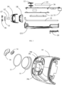
- FIG. 1 is a structural schematic view of a skin care assembly according to an embodiment of the present disclosure.
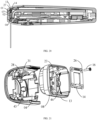
- FIG. 2 is a perspective exploded schematic view of the skin care assembly in FIG. 1 in a direction.
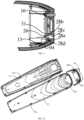
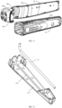
- FIG. 3 is a perspective exploded schematic view of the skin care assembly in FIG. 1 in another direction.
- FIG. 4 is an exploded schematic view of a head portion of the skin care assembly in FIG. 1 in a direction.
- FIG. 5 is a structural schematic diagram of a cold compress component of the skin care assembly in a direction according to an embodiment of the present disclosure.
- a skin care assembly 1 is provided in some embodiments of the present disclosure and includes a cold compress component 01, a refrigeration component 02, a heat sink 03, a first cover 04, and an electrode 06.
- the cold compress component 01 includes a contacting surface 01a, a conducting surface 01b.
- the contacting surface 01a is a portion configured to directly contact a skin.
- a refrigeration side of the refrigeration component 02 is thermally coupled to the conducting surface 01b of the cold compress component 01 to reduce a temperature of the cold compress component 01.
- the heat sink 03 is thermally coupled to a heat-generating side of the refrigeration component 02 to dissipate heat from the refrigeration component 02.
- the first cover 04 is configured to relatively fix the cold compress component 01 to the heat sink 03.
- the electrode 06 is fixed relative to the first cover 04.
- the contacting surface 01a and the conducting surface 01b of the cold compress component 01 are arranged opposite to each other, and the electrode 06 is located on a side where the contacting surface 01a is located.
- the cold compress component 01, the refrigeration component 02 and the heat sink 03 are stacked to form a sandwich structure, which may facilitate an assembly and a heat conduction of the three.
- the cold compress component 01 is in direct contact with the skin.
- the temperature of the cold compress component 01 is reduced by a refrigeration process performed by the refrigeration component 02.
- the heat sink 03 dissipates the heat from the refrigeration component 02.
- the cold compress component 01 is relatively fixed to the heat sink 03 by the first cover 04, such that the heat sink 03 may better cooperate with the refrigeration component 02 to reduce the temperature of the cold compress component 01, reducing a heat return in a short time and increasing a period of the skin care assembly 1 maintaining a temperature balance state.
- the electrode 06 performs a current stimulation and heating for the skin.
- the electrode 06 is relatively fixed to the first cover 04, such that the electrode 06 is close to the skin structurally.
- the electrode 06 cooperates with the cold compress component 01 to achieve a cosmetic effect such as firming the skin and shrinking pores.
- the electrode 06 When the skin care assembly 1 is in operating, the electrode 06 is discharged.
- the electrode 06 may generate a radio frequency or a micro-current.
- the current passes through the skin to stimulate the skin, such that a desired cosmetic effect may be achieved. Since the skin acts as an electrical resistance, a temperature of the skin may be increased.
- the cold compress component 01 and the electrode 06 are fixed relative to the first cover 04.
- the cold compress component 10 and the electrode 06 are both in direct contact with the skin and are adjacent to each other.
- the current of the electrode 06 passing through the skin may cause a muscle having a contraction movement, and the cosmetic effect may be achieved.
- An epidermal temperature and a dermal temperature of the skin may be increased during a discharge process of the electrode 06.
- the temperature of the skin may be increased resulting from a heat generated by skin cells and a heat converted from an electrical energy.
- the cold compress component 01 is configured to reduce a heat generated by the electrode 06 stimulating an epidermis, and reduce a temperature of the epidermis of the skin. In this way, a cold compress and calm effect may be achieved, which may avoid burning the skin due to an excessive temperature, reduce a discomfort feeling in use, and improve a comfort of operating an operating member.
- the refrigeration component 02 performs the refrigeration process for the cold compress component 01, such that the cold compress component 01 may continuously reduce the temperature of the epidermis of the skin.
- a process of hot and cold being alternated may also make the skin expand and contract, enhancing a breath of the skin. In this way, collagen of a dermal layer may be better stimulated to be tightened and regenerated while the skin is protected from a damage, and the skin may be tightened, which may improve the cosmetic effect.
- the skin may be a facial skin.
- a more superficial skin may be the epidermis, and a deeper skin may be a dermis.
- the electrode 06 When operating, the electrode 06 may be discharged and generate the radio frequency or the micro-current, etc., to perform a cosmetic process for the facial skin.
- the electrode 06 may be fixedly mounted on the first cover 04.
- the skin care assembly 1 may be applied in a beauty instrument.
- the number of electrodes 06 may be four.
- the electrodes 06 are arranged on a circumferential side of the cold compress component 01 and spaced from each other. A height of an upper surface of the electrode 06 close to the skin flushes with a height of the contacting surface of the cold compress component 01, that is, the electrodes 06 and the cold compress component 01 may be simultaneously in direct contact with the skin. In this way, the cosmetic effect such as firming the skin and shrinking the pores, etc., may be achieved.
- a material of the cold compress component 01 may be a crystal and/or a metal.
- the cold compress component 01 may be a material having a good thermal conductivity, such as a sapphire, a Topaz, a rock crystal, a glass, or the like, and configured to directly contact the skin and reduce the temperature of the epidermis.
- the cold compress component 01 made of a sapphire material has the good thermal conductivity and is skin-friendly.
- the cold compress component 01 may be in a shape of a circle, an oval, or a polygon.
- the polygon may be, for example, a square, a rectangle, a pentagon, a hexagon, etc.
- the shape of the cold compress component 01 is not specifically limited herein.
- the contacting surface 01a of the cold compress component 01 may have an area between 350 mm 2 and 450 mm 2 , a thickness between 2 mm and 5 mm, and a ratio of the area of the contacting surface 01a of the cold compress component 01to the thickness of the contacting surface 01a of the cold compress component 01 is between 88:1 and 225:1.
- a total power when all electrodes 06 are discharged is between 5 watts and 20 watts.
- a temperature of the dermis of the skin is between 50°C and 70°C.
- An operating power of the refrigeration component 02 is configured to have the temperature of the skin reduced to a range between 15°C and 45°C.
- the electrode 06 may include an arc-shaped body and a fixing portion protruding from the arc-shaped body towards the cold compress component 01, and the first stepped surface 06a is located on a side of the arc-shaped body facing the cold compress component 01.
- Multiple electrodes 06 are spaced from each other, and a circle is defined by arc-shaped bodies of the multiple electrodes 06, which may exactly enclose the contacting surface 01a of the cold compress component 01 or may also partially overlaps with the contacting surface 01a.
- the cold compress component may include the cold compress component 01 and a cold-conducting layer 07.
- the cold-conducting layer 07 is arranged between the cold compress component 01 and the refrigeration component 02 and configured to conduct a heat between the cold compress component 01 and the refrigeration component 02.
- the cold-conducting layer 07 abuts against the cold compress component 01.
- the cold-conducting layer 07 is further arranged between the conducting surface 01b of the cold compress component 01 and the refrigeration side of the refrigeration component 02.
- the conducting surface 01b of the cold compress component may transfer to a side of the cold-conducting layer 07 facing away from the cold compress component and directly contact with the refrigeration side of the refrigeration component 02. Since the cold-conducting layer 07 has a good thermal conductivity, the refrigeration component 02 may efficiently reduce the temperature of the cold compress component 01 through the cold-conducting layer 07.
- the conducting surface 01b of the cold compress component is in direct surface-contact with the refrigeration side of the refrigeration component 02. With a surface-contact manner, the heat conduction may be more sufficient and a conduction effect may be maximized.
- the cold-conducting layer 07 may be made of an aluminum nitride ceramic or other materials having good thermal conductivity. The surface-contact manner may maximize a heat-transferring effect. Both the cold compress component 01 and the cold-conducting layer 07 are made of materials having good heat-transferring performances.
- the cold-conducting layer 07 may be filled with a thermally conductive silicone grease, such that a heat transfer may be more sufficient, a control for the temperature may be smoother, and a feeling of the skin may be more comfortable.
- the skin care assembly 1 may further include a second cover 08, a first mounting plate 35, a second mounting plate 36, an inner housing 11, a button 12, a charging port 10, and a thermally conductive housing 09, or the like.
- the sapphire in some embodiments of the present disclosure may be artificial or natural.
- the skin care assembly 1 may further include a lead wire and a wire groove.
- the lead wire is connected to and fixed on a side of the refrigeration element 02.
- the wire groove is defined in an inner side of the second cover 08 corresponding to the side where the lead wire is arranged of the refrigeration element 02, and defined along an edge of a limiting hole 24.
- lead wires may include at least one lead wire.
- the number of wire grooves is consistent with the number of the lead wires, and the lead wires are accommodated in the wire grooves in a process of assembling the skin care assembly 1, such that the refrigeration component 02 and the heat sink 03 may be connected and fixed together.
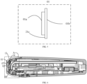
- a skin care assembly 1 is also provided in the present disclosure, as shown in FIGS. 2 and 3 .
- the skin care assembly 1 may include the operating member, a mounting bracket 03, and a circuit board.
- the operating member includes a cold compress component 01 and a refrigeration component 02 located at a head portion of the skin care assembly 1, and has a contacting surface 01a configured to directly contact the skin and reduce a temperature of the skin.
- the mounting bracket 03 includes a first mounting position and a second mounting position. The operating member is fixed to the mounting bracket 03 through the first mounting position, and the circuit board is fixed to the mounting bracket 03 through the second mounting position.
- the operating member is located at the head portion of the skin care assembly 1, and the mounting bracket 03 extends from the head portion of the skin care assembly 1 to a tail of the beauty instrument.
- Both the operating member and the circuit board are mounted on the mounting bracket 03, such that the assembly of each component of the skin care assembly 1 may be more centralized. In this way, a convenient assembly may be achieved, and an overall structure of the skin care assembly 1 may be more compact, such that a volume of the skin care assembly 1 may be reduced.
- the mounting bracket 03 may also serves as a heat sink to dissipate a heat from the beauty instrument while the mounting bracket 03 is mounted with various components.
- the mounting bracket 03 is in tight contact with a component such as the operating member in the beauty instrument, which is conducive to a sufficient and uniform heat dissipation.
- the mounting bracket 03 may absorb the heat in the whole beauty instrument, making the heat dissipation more efficient.
- the mounting bracket 03 extending to the tail of the beauty instrument allows the heat to stay for a longer time and not to backtrack in a short time, which increasing a refrigeration period of the operating member.
- the skin care assembly may include the thermally conductive housing 09, and the mounting bracket 03 includes a third mounting position configured to mount the thermally conductive housing 09.
- a side surface of the mounting bracket 03 defines a groove, and both the second mounting position and the third mounting position are arranged or defined in the groove.
- the second mounting position in the groove, may be located at a position having a depth different from a depth of a position where the third mounting position is located, such that the circuit board and the thermally conductive housing 09 may be stacked.
- the second mounting position is farther from a bottom of the groove than the third mounting position.
- a ratio of a distance from the second mounting position to the bottom of the groove to a distance from the third mounting position to the bottom of the groove may be between 1.5 and 3 times.
- the skin care assembly includes the first mounting plate 36 and the button 12.
- the button 12 is arranged on the first mounting plate 36.
- a side wall of the groove is arranged with a step, and the circuit board is fixed in the groove through the step.
- the first mounting plate 36 is fixed to the side wall of the groove, and is located on a side of the circuit board facing away from the bottom of the groove.
- the skin care assembly includes a second mounting plate 35.
- the circuit board is mounted on the second mounting plate 35, the second mounting plate 35 is mounted on the step, and the second mounting plate 35 is spaced from the bottom of the groove.
- the first mounting plate 36 extends to the tail of the skin care assembly, and an end of the first mounting plate 36 away from the operating member is defined with a charging port 10 configured to be connected to the circuit board.
- first mounting board 36 and the second mounting board 35 themselves may also be circuit boards.
- a ratio of a length of the second mounting plate 35 to a length of the mounting bracket 03 is between 1.2 and 2.
- the charging port 10 is spaced from the mounting bracket 03 by a certain distance, and the distance is between 1 cm and 3 cm.
- the mounting bracket 03 defines a receiving cavity.
- the receiving cavity is defined on a side surface of the first mounting position and configured to accommodate a part of the lead wires in the skin care assembly.
- the mounting bracket 03 extends from the head portion of the skin care assembly 1 to the tail of the skin care assembly 1.
- the operating member cools down the skin or a surface layer of an adjacent tissue of the skin, and a depth of action of an electricity, a magnetism, or an electromagnetic emitted by the electrodes on the skin is greater than that on the surface layer.
- an area of the contacting surface 01a is greater than an area where the electrodes act on the skin.
- the skin care assembly 1 further includes the charging port 10.
- the charging port 10 is arranged at an ending end of the second mounting plate 36 and exposed out of the skin care assembly 1.
- the second mounting plate 36 may be configured to be mounted with a component or an element necessary for the skin care assembly 1 such as the circuit board, a battery, etc.
- the skin care assembly 1 may be used when powered on or after charged. When used after charged, the skin care assembly 1 charges for the battery by the charging port 10 being connected to an external power cord.
- the charging port 10 When the skin care assembly 1 is used when powered on, the charging port 10 may generate a certain impedance due to adopting a point-contact manner inside the charging port 10, and heat may be generated when a current passes through the charging port 10.
- the charging port 10 is defined at an end of a mounting plate and away from the heat sink 03, which may avoid the heat generated by the charging port 10 backtracking to the skin care assembly 1 or even the operating member.
- the heat generated by the charging port 10 backtracking to the skin care assembly 1 or the operation head may affect a refrigeration effect of the refrigeration component 02, thereby affecting the cosmetic effect.
- the skin care assembly 1 further includes an airflow driver.
- the airflow driver is arranged opposite to the heat sink and configured to drive airflow near the heat sink to flow so as to enhance a heat-dissipating effect.
- the airflow driver may be arranged on a position of the skin care assembly 1 close to the head portion.
- the airflow driver drives the airflow to flow from the head portion to the tail of the skin care assembly 1 and be discharged from an air outlet at the tail of the skin care assembly 1.
- the airflow driver is a fan, and the fan is located at the head portion and blows air against the heat sink 03.
- the tail of the skin care assembly 1 defines the air outlet corresponding to a tail of the heat sink 03 to discharge the airflow carrying heat.
- the heat sink 03 extends from the head portion of the skin care assembly 1 to the tail of the skin care assembly 1.
- An end of the heat sink 03 located at the tail of the skin care assembly 1 is spaced from the tail by a gap, and a size of the gap is less than one third of a length of the skin care assembly 1.
- the heat sink 03 includes the second cover 08 and a heat-dissipating body 031.
- the second cover 08 is disposed between the heat-dissipating body 031 and the first cover 04, and fixed to the heat-dissipating body 031.
- the first cover 04 is fixed on the second cover 08.
- the second cover 08 may be a light-transmitting plate 13.
- the second cover body 08 further defines the limiting hole 24.
- a position of the limiting hole 24 corresponds to a position of a first opening 50 of the first cover 04.
- the limiting hole 24 is fluidly communicated with the first opening 50 of the first cover 04.
- a part of the refrigeration component 02 is arranged in the limiting hole 24, and an edge of the refrigeration component 02 is 0.5-1 mm away from an edge of the limiting hole 24.
- a ratio of an area of the limiting hole 24 to an area of the first opening 50 of the first cover 04 is between 0.8 and 1.2.
- FIG. 12 is a structural schematic view of a heat-dissipating body of the skin care assembly in a direction according to an embodiment of the present application.
- FIG. 13 is a structural schematic view of the heat-dissipating body shown in FIG. 11 in a second direction.
- FIG. 14 is a structural schematic view of the heat-dissipating body shown in FIG. 11 in a third direction.
- a skin care assembly 1 is further provided in the present disclosure and includes a heat pipe 32 and a heat-dissipating body 031.
- An end of the heat pipe 32 is thermally coupled to an end of the heat-dissipating body 031 close to the second cover 08, and the other end of the heat pipe 32 extends along a direction away from the refrigeration component 02 and is thermally coupled to the heat-dissipating body 031.
- the heat-dissipating body 031 itself has a heat-dissipating function, and the heat pipe 32 assists the heat-dissipating body 031 to dissipate the heat, thereby improving a heat-dissipating efficiency of the heat-dissipating body 031.
- the end of the heat pipe 32 is thermally coupled to the end of the heat-dissipating body 031 close to the second cover 08, and the other end of the heat pipe 32 extends along the direction away from the refrigeration component 02, such that a path for transferring the heat may be long enough to avoid the heat backtracking to the head portion of the beauty instrument in a short time, and a refrigeration period of the beauty instrument may be increased.
- a section of the heat pipe 32 is bent to form a bent portion, and the bent portion abuts against the end of the heat-dissipating body 031 close to the second cover 08.
- An inside of the heat pipe 32 has a hollow and closed structure, with liquid filled inside. The heat pipe 32 is not filled up with the liquid.
- the heat-dissipating body 031 defines an escape groove 03c.
- the heat pipe 32 is arranged along an inner wall of the escape groove 03c, at least partially embedded in the escape groove 03c, and welded to the inner wall of the escape groove 03c.
- An end of the heat pipe 32 away from the bent portion extends to an ending end of the heat-dissipating body 031, such that a contact between the 32 and the heat-dissipating body 031 may be more sufficient, which may improve a heat-dissipating performance of the heat sink 03.
- a contacting portion 03b is arranged on a side surface of the heat-dissipating body 031 close to the refrigeration component 02.
- a position of the contacting portion 03b corresponds to the position of the limiting hole 24.
- the heat-generating side of the refrigeration component 02 may be thermally coupled to the contacting portion 03b through the limiting hole 24.
- a part of the contacting portion 03b is located in the limiting hole 24, attached to the heat-generating side of the refrigeration element 02, and fixed relative to the heat-generating side of the refrigeration element 02.
- the heat-dissipating body 031 is made of aluminum by means of integral molding. An end of the heat-dissipating body 031 away from the escape groove 03c has a heat-dissipating fin structure.
- FIG. 18 is an exploded schematic view of the head portion of the skin care assembly according to another embodiment of the present disclosure.
- FIG. 19 is a structural schematic view of a side of a light-transmitting plate close to a phototherapy lamp plate of the skin care assembly according to another embodiment the present disclosure.
- FIG. 20 is a cross-sectional schematic view of the skin care assembly according to another embodiment of the present disclosure.
- FIG. 21 is an exploded schematic view of the first cover, the light-transmitting plate, the phototherapy lamp plate, and a first bolt of the skin care assembly according to another embodiment of the present disclosure.
- FIG. 19 is a structural schematic view of a side of a light-transmitting plate close to a phototherapy lamp plate of the skin care assembly according to another embodiment the present disclosure.
- FIG. 20 is a cross-sectional schematic view of the skin care assembly according to another embodiment of the present disclosure.
- FIG. 21 is an exploded schematic view of the first cover, the light-transmitting plate, the phototherapy lamp plate, and
- FIG. 22 is a cross-sectional schematic view of an assembly of the first cover, the light-transmitting plate, the phototherapy lamp plate, and the first bolt of the skin care assembly according to another embodiment of the present disclosure.
- FIG. 23 is a structural schematic view of the first cover, the second cover, and the inner housing of the skin care assembly according to an embodiment of the present disclosure.
- the skin care assembly may further include a phototherapy lamp board 14, multiple phototherapy lamps 25 are arranged on a side of the phototherapy lamp board 14 close to the first cover 04, and an escape hole 29 is defined in a center of the phototherapy lamp board 14.
- the multiple phototherapy lamps 25 are arranged around the escape hole 29, and may exactly be covered by a projection of the cold compress component 01 in a direction perpendicular to the contacting surface 01a.
- the refrigeration component 02 and the cold-conducting layer 07 may pass through the escape hole 29 to be directly contacted with the cold compress component 01.
- the phototherapy lamp board 14 is arranged opposite to the heat sink 03, and a side of the phototherapy lamp board 14 without the phototherapy lamps 25 is abutted against and thermally coupled to the heat sink 03.
- the escape hole 29 has a position-limiting action on a first limiting portion 30 protruding from the heat sink 03, such that the phototherapy lamp board 14 and the heat sink 03 may be fixed relative to each other.
- the first limiting portion 30 is thermally coupled to the refrigeration component 02.
- the light-transmitting plate 13 may be arranged between the phototherapy lamp plate 14 and the first cover 04.
- a second through hole 24 is defined in a center of the light-transmitting plate 13 and opposite to the escape hole 29.
- Several light-transmitting portions 27 are defined around the second through hole 24.
- the light-transmitting portions 27 are defined corresponding to the phototherapy lamps 25, and may exactly be covered by the projection of the cold compress component 01 in the direction perpendicular to the contacting surface 01a.
- the light-transmitting portions 27 are covered with light-transmitting materials, and light emitted by the phototherapy lamps 25 may pass through the light-transmitting portions 27 and be mapped to the cold compress component 01.
- the refrigeration component 02 and the cold-conducting layer 07 may pass through the second through hole 24 to be directly contacted with the cold compress component 01.
- the second through hole 24 may have a position-limiting action on the refrigeration component 02.
- the phototherapy lamp board 14 defines multiple first fixing holes 26.
- the first fixing holes 26 are located opposite to third fixing holes 28d in the first cover 04, and configured to fix the phototherapy lamp board 14 relative to the first cover 04.
- the phototherapy lamp board 14, the first cover 04, and the light-transmitting plate 13 may be relatively fixed in a way of snapping, latching, mortising, or thread-bolt connecting.
- a connection manner provided in the embodiment is the thread-bolt connecting.
- An inner wall of the first fixing hole 26 and an inner wall of the third fixing hole 28d also define threads corresponding to a first bolt 16.
- Several first bolts 16 may pass through the first fixing holes 26 and the third fixing holes 28d to have the phototherapy lamp board 14 and the first cover 04 relatively fixed.
- the light-transmitting plate 13 defines several second fixing holes 23, and the number of the second fixing holes 23 is the same as the number of the first fixing holes 26, the number of the third fixing holes 28 d, and the number of the first bolts 16.
- a side of the first cover 04 close to the light-transmitting plate 13 defines a sinking groove 31, and a shape and an outer diameter of the sinking groove 31 are approximately the same as those of the second fixing holes 23. That is, the second fixing holes 23 may have a position-limiting action on the sinking groove 31.
- the third fixing hole 28d penetrated through the sinking groove 31, such that the phototherapy lamp board 14, the light-transmitting board 13, and the first cover 04 may be relatively fixed by the first bolts 16 in a sequence as above.
- the phototherapy lamps 25 may be LED light-emitting lamp beads, and light emitted by the phototherapy lamps 25 exiting to the cold compress component 01 through the light-transmitting portions 27 may appear as red light, which may generate an effect of performing a phototherapy for the skin. Further, the phototherapy lamps 25 may also have other functions, such as a hair removal.
- the light-transmitting materials covered on the light-transmitting portions 27 may be mostly organic or inorganic materials with good light-transmitting performances, such as various optical plastics, silicate glasses, or the like.
- the light-transmitting plate 13 may not be disposed between the phototherapy lamp plate 13 and the first cover 04, and the light emitted by the phototherapy lamps 25 may be directly mapped to the cold compress component 01.
- FIG. 15 is a schematic view of an assembly of the first cover, a second cover, and a heat sink of the skin care assembly according to an embodiment of the present disclosure.
- FIG. 16 is a cross-sectional schematic view of the skin care assembly according to an embodiment of the present disclosure.
- FIG. 17 is a partial enlarged view of a position B in FIG. 15 .
- the skin care assembly 1 includes a cold compress component 01, a refrigeration component 02, a heat sink 03, a first cover 04, a pulse-generating circuit 05, and an electrode 06.
- the cold compress component 01 includes a contacting surface 01a and a conducting surface 01b, and the contacting surface 01a is configured to directly contact the skin.
- a refrigeration side of the refrigeration component 02 is thermally coupled to the conducting surface 01b of the cold compress component 01 to reduce a temperature of the cold compress component 01.
- the heat sink 03 is thermally coupled to a heat-generating side of the refrigeration component 02 to dissipate heat from the refrigeration component 02.
- the first cover 04 is configured to relatively fix the cold compress component 01 to the heat sink 03, and at least partially wrap or accommodate the cold compress component 01 and the heat sink 03.
- the pulse-generating circuit 05 is arranged on a side of the heat sink 03 facing away from the refrigeration component and configured to generate an electric/magnetic pulse.
- the electrode 06 is relatively fixed to the first cover 04 and protrudes relative to the first cover 04.
- the electrode 06 is connected to the pulse-generating circuit. When the electrode 06 directly contacts the skin, the pulse-generating circuit 05 may generate the electric/magnetic pulse to maintain the skin.
- a cold-conducting layer may be arranged between the heat-generating side of the refrigeration component 02 and the heat sink 03, and filled with a thermally conductive silicone grease, so as to have a more sufficient heat transfer and also make a control for the temperature smoother. In this way, a feeling of the skin may be more comfortable.
- both the cold compress component 01 and the electrode 06 are fixed on the first cover 04, such that the cold compress component 01 and the electrode 06 may be better fixed, increasing a structural stability thereof.
- both the refrigeration component 02 and the pulse-generating circuit 05 are arranged on the heat sink 03, and the pulse-generating circuit 05 is located on the side of the heat sink 03 facing away from the refrigeration component, which improves the heat-dissipating efficiency of the care component 1 with reducing an interference of the heat generated by the refrigeration component 02 and the pulse-generating circuit 05 on the cold compress component 01.
- the electrode 06 is fixed on the first cover 04, such that a structure for mounting the electrode 06 may be avoided to be processed on a component such as the cold compress component 01, reducing a processing cost accordingly.
- the first cover 04 may include two side surfaces, i.e., an outer side surface and an inner side surface.
- the outer side surface is exposed to air and is configured to fix the electrode 06 and the cold compress component 01
- the inner side surface is configured to wrap or accommodate the refrigeration component 02 and partially wrap or accommodate the heat sink 03 and the cold compress component 01.
- four first mounting holes 04b are defined in the inner side surface of the first cover 04 and configured to fix the first cover 04.
- the heat sink 03 includes a first end, and a first end of the heat sink 03 defines four second mounting holes.
- the first mounting holes 04b in the cover body 04 are assembled corresponding to the four second mounting holes in the heat sink 03 and fixed by screws. Subsequently, the first end of the heat sink 03 is wrapped or accommodated by the first cover 04 in an inner side of the first cover 04.
- the heat-generating side of the refrigeration component 02 is connected and thermally coupled to the first end of the heat sink 03, and both the heat-generating side of the refrigeration component 02 and the first end of the heat sink 03 are wrapped or accommodated by the first cover 04.
- the refrigeration side of the refrigeration component 02 is thermally coupled to the conducting surface 01b of the cold compress component 01, and both the refrigeration side of the refrigeration component 02 and the conducting surface 01b of the cold compress component 01 are wrapped or accommodated by the first cover 04.
- the contacting surface 01a of the cold compress component 01 and the electrode 06 are both located on an outer side of the first cover 04, such that the skin care assembly 1 may perform an electromagnetic pulse therapy for the skin through the electrode 06 during operating while also protecting the skin by reducing the temperature of the skin through the cold compress component 01, so as to improve a skin care effect of the skin care assembly 1 for the skin.
- a first accommodating cavity is defined between the first end of the heat sink 03 and a second end of the heat sink 03.
- the second end of the heat sink 03 described above is an end of the heat sink 03 connected to the first end of the heat sink 03 and away from the heat-generating side of the refrigeration component 02.
- a supporting frame is arranged in the first accommodating cavity.
- the pulse-generating circuit 05 is fixed on the supporting frame of heat sink 03. When the skin care assembly 1 is in operating, the heat generated by the refrigeration component 02 and the pulse-generating circuit 05 is directly conducted to the heat sink 03 and dissipated through the heat sink 03 based on a high heat-dissipating performance of the heat sink 03.
- the first cover 04 may include the two side surfaces, i.e., the outer side surface and the inner side surface.
- the inner side surface and the outer side surface are fluidly communicated to each other through the first opening 50.
- a mounting platform is arranged on the outer side of the first cover 04.
- the cold compress component 01 is fixed on the mounting platform in the outer side of the first cover 04 through being pressed by the electrode 06.
- the inner side of the first cover 04 defines a first receiving cavity.
- a part of components including the heat sink 03 of the skin care assembly 1 are wrapped or accommodated by the first cover 04 or partially wrapped or accommodated in the first receiving cavity.
- the conducting surface 01b of the cold compress component 01 passes through the first opening 50 between the inner side surface and outer side surface of the first cover 04 and abuts against one side of the heat sink 03.
- FIG. 6 is a cross-sectional schematic view of the skin care assembly according to an embodiment of the present disclosure.
- FIG. 7 is a partial enlarged view of a position A in FIG. 6 .
- FIG. 8 is an exploded schematic view of an electrode and a first cover of the skin care assembly in a direction according to some embodiments of the present disclosure.
- FIG. 9 is a cross-sectional schematic view of an assembling position of the electrode of the skin care assembly according to some embodiments the present disclosure.
- the electrode 06 is configured in a crescent shape and has two special ends.
- An end of the two special ends is a body portion configured to maintain the skin by adopting the electric/magnetic pulse during the electrode 06 being in operating.
- the other end of the two special ends is a fixing portion.
- the fixing portion is connected to the first cover 04, such that the electrode 06 may be fixed on the mounting platform in the outer side of the first cover 04.
- the fixing portion faces towards the mounting platform in the outer side of the first cover 04 during being mounted.
- the fixing portion includes at least one mounting column 06a.
- At least one mounting hole 28c is defined on the mounting platform of the first cover 04.
- the electrode 06 may be fixed to the first cover 04 through the at least one mounting column 06a being mounted in the at least one mounting hole 28c.
- a height of the electrode 06 protruding relative to the first cover 04 is between 0mm-20mm.
- a first sinking hole 28a is defined in the mounting platform of the first cover 04, and slightly lower than the mounting platform.
- the first sinking hole 28a has a shape corresponding to the shape of the electrode 06 and is configured to fix the electrode 06 on the mounting platform and preventing the electrode 06 from being shaked or shifted.
- a gasket 34 for sealing and absorbing a shock may be arranged between the first cover 04 and the electrode 06.
- a second sinking hole 28b configured to accommodate the gasket 34 is defined in the second sinking hole 28b of the mounting platform.
- the second sinking hole 28b has a shape corresponding to a shape of the gasket 34.
- At least one third through hole 34a is defined in the gasket 34.
- the number of the at least one third through hole 34a matches the number of the at least one mounting column 06a, and a shape of the at least one third through hole 34a is adapted to a cross-sectional shape of the at least one mounting column 06a, such that the at least one mounting column 06a passes through the at least one third through hole 34a to fix the gasket 34 between the first cover 04 and the electrode 06.
- other corresponding fixed facilities may also be arranged on the gasket 34, the electrode 06, and the first cover 04 to prevent the gasket 34 from being shifted.
- the gasket 34 may be made of a material such as a silica gel, etc., which may be capable of occurring an elastic deformation and have a greater friction coefficient.
- the shape of the gasket 34 may be adapted to the shape of the electrode 06, and has a size less than a size of the shape of the electrode 06.
- the cold compress component 01 is located in the first opening 50 of the first cover 04.
- the cold compress component 01 has a first radial size and a second radial size different from the first radial size at positions corresponding to different thicknesses.
- the first opening 50 has a third radial size and a fourth radial size different from the third radial size at positions corresponding to different depths.
- a portion of the cold compress component 01 having the first radial size is closer to the cold-conducting layer 07 than a portion of the cold compress component 01 having the second radial size.
- a portion of the first opening 50 having the third radial size is closer to the cold-conducting layer 07 than a portion of the first opening 50 having the fourth radial size.
- the first radial size is less than the third radial size
- the second radial size is less than the fourth radial size
- the second radial size is greater than the third radial size.
- a first stepped surface 21c is arranged between the portion having the first radial size and the portion having the second radial size of the cold compress component 01.
- a second stepped surface 22a is arranged between the portion having the third radial size and the portion having the fourth radial size of an inner side of the first opening 50 of the first cover 04.
- An outer side of the first opening 50 of the first cover 04 is arranged with the mounting platform.
- the electrode 06 is mounted on the mounting platform on the outer side of the first cover 04, and is configured to maintain the skin.
- the refrigeration component 02, the cold-conducting layer 07, and the cold compress component 01 abut against the first end of the heat sink 03 in sequence, and are fixed between the first cover 04 and the first end of the heat sink 03 through the second stepped surface 22a in the inner side of the first cover 04 abutting against and being attached to the first stepped surface 21c of the cold compress component 01.
- the contacting surface 01a of the cold compress component 01 passes through the first opening 50 of the first cover 04 and is located on the outer side of the first cover 04, configured to assist the electrode 06 to maintain the skin.
- a first sealing component 33 for sealing and absorbing the shock may be arranged between the first opening 50 of the first cover 04 and the cold compress component 01.
- the first sealing component 33 is arranged between the first stepped surface 21c and the second stepped surface 22a.
- the first sealing component 33 may be deformed by a force, such that an inside of the machine body of the skin care assembly 1 may be isolated from an external environment.
- the first sealing component 33 may serve as a buffer when the machine body is bumped or dropped.
- a shape of the first sealing component 33 may be adapted to a shape of the first stepped surface 21c.
- other corresponding fixed facilities may also be arranged between the first sealing component 33, the cold compress component 01, and the first cover 04 to prevent the first sealing component 33 from being shifted.
- the first sealing component 33 may be made of the material such as the silica gel, etc., which may be elastically deformed and have the greater friction coefficient.
- FIG. 10 is a structural schematic view of the first cover and an inner housing of the skin care assembly in a direction according to some embodiments the present disclosure.
- FIG. 11 is a structural schematic view of the first cover and the inner housing of the skin care assembly in another direction according to some embodiments the present disclosure.
- the skin care assembly 1 may further include the inner housing 11 and an outer housing 37.
- the skin care assembly 1 may be at least partially arranged in the inner housing 11.
- the heat sink 03 is partially arranged in the inner housing 11 and fixed relative to the inner housing 11, and the inner housing 11 is partially arranged in an inner side of the outer housing 37.
- a second fastener 37b is fixed on the outer housing 37, and a first fastener 04d is fixed on the first cover 04. The second fastener 37b is snapped to the first fastener 04d.
- the first fastener 04d is fixed on the first cover 04
- the second fastener 37b is fixed on the outer housing 37, such that it may be more convenient for the skin care assembly 1 to be mounted and aligned and have an accessory replaced when the skin care assembly 1 is assembled.
- a part of the second fastener 37b is arranged on a side of the outer housing 37 close to a thermally coupling surface of the heat sink 03, i.e., a side where a cavity opening of an empty cavity for accommodating the heat sink 03 of the outer housing 37 is located, and close to a side wall 04c of the first cover 04.
- the first cover 04 includes the side wall 04c corresponding to the outer housing 37, and the first fastener 04d is arranged on two side walls 04c of the first cover 04.
- the first fastener 04b may define a bayonet, an edge of the bayonet may be arranged with an inclined surface 04e.
- the second fastener 37b may include a hook. Under a guide of the inclined surface 04e, the hook of the second fastener 37b may enter into the bayonet of the first fastener 04b to complete a snap connection. In this way, the side walls 04c of the first cover 04 may be assembled with the outer housing 37.
- the side walls 04c may be arranged with multiple first fasteners 04d and inclined surfaces 04e.
- the inner side of the outer housing 37 may be also arranged with the second fasteners 37b corresponding to the first fasteners 04d in the number and positions. No specific restrictions are made herein.
- the first fasteners 04d on the side walls 04c and the second fasteners 37b on the inner side of the outer housing 37 may be correspondingly arranged asymmetrically.
- an upper side and a lower side are distinguished based on the button 12, the numbers of the first fasteners 04d and the second fasteners 37b close to the upper side are different from those of the ones close to the lower side, such that front and back for mounting of the side walls 04c of the first cover 04 and front and back for mounting of the outer housing 37 may be clearly distinguished, and a foolproof effect may be achieved.
- the skin care assembly 1 provided in some embodiments of the present disclosure further includes a third fastener 11b and a fourth fastener 37a.
- Fourth fasteners 37a are fixed on an edge of the outer housing 37, and third fasteners 11b are fixed on edges of two side surfaces of the inner housing 11.
- the third fasteners 11b are snapped to the fourth fasteners 37a.
- the third fasteners 11b are arranged on the inner housing 11, and the fourth fasteners 37a are arranged on the outer housing 37, such that it may be more convenient for the skin care assembly 1 to be mounted and aligned and have the accessory replaced when the skin care assembly 1 is assembled.
- the third fasteners 11b are arranged on the edges of the two side surfaces of the inner housing 11, generally by arranging several third fasteners 11b from a head portion of the inner hosing 11 to a tail of the inner housing 11.
- the fourth fasteners 37a are arranged on the inner side of the outer housing 37 at positions corresponding to the third fasteners 11b. Since a shape of the outer housing 37 fit for shapes of the two side surfaces of the inner housing 11, several third fasteners 11b are arranged along the edge of the outer housing 37 from a head portion of the outer housing 37 to a tail of the outer housing 37.
- the third fasteners 11b may include bayonets, edges of the bayonets may be arranged with inclined surfaces.
- the second fasteners 37b may include hooks. Under guides of the inclined surfaces, the hooks of the second fasteners 37b may enter into the bayonets of the first fasteners 11b to complete a snap connection. In this way, the two side surfaces of the inner housing 11 may be assembled with the outer housing 37.
- the edges of the two side surfaces of the inner housing 11 may be arranged with multiple third fasteners 11b and inclined surfaces.
- the inner side of the outer housing 37 may be also arranged with the fourth fasteners 37a corresponding to the third fasteners 11b in the number and positions. No specific restrictions are made herein.
- the third fasteners 11b on the edges of the two side surfaces of the inner housing 11 and the fourth fasteners 37a on the inner side of the outer housing 37 may be correspondingly arranged asymmetrically.
- a front side and a rear side are distinguished based on the button 12, the numbers of the third fasteners 11b and the inclined surfaces arranged on the edges of the side surfaces of the inner housing 11 on the front side, and the fourth fasteners 37a are different from those on the rear side. In this way, front and back for mounting may be clearly distinguished, and the foolproof effect may be achieved.
- FIG. 23 is a structural schematic view of the first cover, the second cover, and the inner housing of the skin care assembly according to an embodiment of the present disclosure.
- FIG. 24 is a structural schematic view of the inner housing of the skin care assembly according to an embodiment of the present disclosure.
- FIG. 25 is a structural schematic view of the second cover and the heat sink of the skin care assembly according to an embodiment of the present disclosure.
- the first cover 04 includes a first panel portion 48 parallel to the contacting surface of the cold compress component 01, and a first side wall extending along a direction from a side edge of the first panel portion 48 towards the heat sink 03, such that the first receiving cavity may be defined in the inner side of the first cover 04.
- the first opening 50 is defined in the first panel portion 48, the contacting surface of the cold compress component 01 is exposed to an outer side of the first receiving cavity from the first opening 50 to directly contact the skin.
- the second cover 08 includes a second panel portion 49 parallel to the first panel portion 48, and a second side wall 47 extending along a direction from a side edge of the second panel portion 49 towards the heat sink 03.
- a second receiving cavity is defined in the inner side of the second cover 08.
- the second panel portion 49 defines a second opening 51.
- the conducting surface of the heat sink 01 is exposed to the second receiving cavity through the second opening 51, so as to be thermally coupled to the refrigeration component 02.
- the second cover 08 is embedded in the first receiving cavity of the first cover 04 and fixed to the first cover 04.
- the cold compress component 01 is fixed between the first panel portion 48 of the first cover 04 and the second panel portion 49 of the second cover 08.
- the skin care assembly 1 in some embodiments of the present disclosure further includes a first mounting column 41 and defines a first mounting hole 42a.
- the first mounting column 41 is arranged in the second receiving cavity of the second cover 08.
- a mounting ear 42 extends radially from a side edge of the heat sink 03, the first mounting hole 42a is defined in the mounting ear 42.
- the number of the mounting ear 42 corresponds to the number of the first mounting column 41.
- An end of the heat sink 03 thermally coupled to the refrigeration component 02 is partially embedded in the second receiving cavity of the second cover 08 and fixed to the second cover 08.
- an end of the first mounting column 41 close to the first mounting hole 42a defines a threaded hole, and a first stud penetrates into the threaded hole at the end of the first mounting column 41 from the first mounting hole 42a of the mounting ear 42 to screw the heat sink 03 to the second cover 08.
- the first stud passes through the first mounting hole 42a and be connected to the threaded hole at the end of the first mounting column 41 from a side of the mounting ear 42 facing away from the second cover 08.
- the skin care assembly 1 in some embodiments of the present disclosure further defines an accommodating cavity 53 and an opening 52.
- the accommodating cavity 53 is defined in the inner side of the inner housing 04, and extends from the head portion of the inner housing 11 to the tail of the inner housing 04.
- the opening 52 is defined at an end of the accommodating cavity 53 close to the refrigeration component 02.
- the heat sink 03 is partially embedded in the accommodating cavity 53 through the opening 52.
- the end of the heat sink 03 thermally coupled to the refrigeration component 02 is partially exposed to an outer side of the accommodating cavity 53 through the opening 52, and a portion of the heat sink 03 partially exposed to the outer side of the accommodating cavity 53 through the opening 52 is partially embedded in the first receiving cavity of the first cover 04.
- the skin care assembly 1 in some embodiments of the present disclosure further includes a second mounting column 38, and defines a first through hole 39 and a second mounting hole 40.
- the second mounting column 38 is arranged in the first receiving cavity of the first cover 04, the first through hole 39 corresponding to the second mounting column 38 is defined in the second receiving cavity of the second cover 08, and the second mounting hole 40 corresponding to the second mounting column 38 is defined in the inner housing 11.
- a diameter of the first through hole 39 is close to and slightly greater than a diameter of the second mounting column 38.
- the second mounting column 38 may be arranged in the first receiving cavity of the first cover 04 at a transiting position between the first panel portion 48 and the first side wall 46.
- the first through hole 39 may be arranged in a transiting position between the second panel portion 49 and the second side wall 47, so as to cooperate with the second mounting hole 40.
- the second mounting hole 40 is defined in a wall of the accommodating cavity of the inner housing 11 and close to the opening 52.
- a mounting rib 40a is arranged in the accommodating cavity 53 of the inner housing 11 and extends from the opening 52 to a tail of the accommodating cavity 53.
- a mounting groove 40b recessed along a direction towards the accommodating cavity 53 is defined in an outer side of the inner housing at a position corresponding to the mounting rib 40a. Due to existence of the mounting rib 40a and the mounting groove 40b, the second mounting hole 40 is close to a top end of the second mounting column 38 and exposed to an end of the mounting rib 40a close to the opening 52, and a bottom of the second mounting hole 40 is exposed to an end of the mounting groove 40b close to the opening 52.
- an end of the second mounting column 38 close to the second mounting hole 40 defines a threaded hole
- a second stud may penetrate into a top end of the second mounting hole 40 and pass out a bottom end of the second mounting hole 40, and be screwed to the threaded hole in the end of the second mounting column 38 passing through the first through hole 39, such that the first cover 04 and the inner housing 11 are fixed.
- the skin care assembly 1 in some embodiments of the present disclosure further includes a third mounting column 43, and defines a third mounting hole 44.
- the third mounting column 43 is arranged in the first receiving cavity of the first cover 04, and the third mounting hole 44 corresponding to the third mounting column 43 is defined in the second panel portion 49 of the second cover 08.
- An end of the third mounting column 43 close to the third mounting hole 44 defines a threaded hole.
- a third stud may pass through the third mounting hole 44 and be screwed to the threaded hole in the end of the third mounting column 43, such that the second cover 08 may be fixed to the first receiving cavity of the first cover 04.
- the cold compress component 01 may be fixed to the first receiving cavity of the first cover 04, and located between the first cover 04 and the second cover 08.
- the third mounting hole 44 penetrates through the second panel portion 49 and fluidly communicate to the second receiving cavity of the second cover 08.
- the conducting surface of the cold compress component 01 may be exposed through the second through hole 24 and thermally coupled to the refrigeration component 02.
- FIG. 26 is a structural schematic view of a second sealing component and the second cover of the skin care assembly according to an embodiment of the present disclosure.
- the skin care assembly 1 in some embodiments of the present disclosure may further include a second sealing component 45 arranged on the second cover 08.
- the second sealing component 45 is attached to a surface of the transiting portion between the second panel portion 49 and the second side wall 47 of the second cover 08 and tightly attached to the second cover 08.
- the second sealing component 45 may be deformed due to being extruded by the first cover 04, such that a gap between the second cover 08 and the first receiving cavity of the first cover 04 may be blocked, preventing water and oil from entering into the second receiving cavity of the second cover 08 and affecting a stability of an interior circuit.
- a material of the second sealing component 45 may be an elastic material such as the silica gel, a latex, or the like, and may also be a poured liquid glue.
- the skin care assembly 1 further includes the first cover 04, at least partially located between the first cover 04 and the heat sink 03.
- the second cover 08 is fixed to the heat sink 03, and the cover 04 is fixed to the second cover 08.
- the cold compress component 01 tightly presses the cold-conducting layer 07 and the refrigeration component 02 against the heat sink 03 in a first direction.
- the second cover 08 is sleeved in the inner side of the first cover 04 and is at least partially located between the first cover 04 and the heat sink 03, and configured to limit a shit of the heat sink 03 in the first direction.
- the first direction mentioned herein is a direction perpendicular to both the first cover 04 and the second cover 08.
- Four first positioning holes corresponding to the first mounting holes and the second mounting holes are defined in the second cover 08.
- Four positioning columns 04a are defined in the inner side of the first cover 04.
- the first mounting holes 04b of the first cover 04 are defined in the four positioning columns 04a. During mounting, the four positioning columns on the first cover 04 pass through the first positioning holes in the second cover 08 and abut against the second positioning hole in the heat sink 03, and are finally fixed by means of screws.
- the second cover 08 may be fixed between the first cover 04 and the heat sink 03.
- the cold compress component 01 which has been fixed on the first cover 04 passes through the first cover 04 and presses the cold-conducting layer 07 and the refrigeration component 02 tightly to the heat sink 03 along the direction perpendicular to both the first cover 04 and the second cover 08.
- the second cover body 08 further defines a limiting hole.
- the limiting hole is located at the opening of the first cover 04 and communicated fluidly to the opening.
- a part of the refrigeration component 02 is arranged in the limiting hole, and an edge of the refrigeration component 02 is 0.5-1 mm away from an edge of the limiting hole.
- a region of the heat sink 03 corresponding to the refrigeration component 02 defines a groove. The groove corresponds to the limiting hole.
- a part of the refrigeration component 02 is embedded in the groove and the other part of the refrigeration component 02 is located in the limiting hole.
- a ration of an area of the limiting hole to an area of the opening is between 0.8 and 1.2.
- the second cover 08 defines the limiting hole corresponding to the opening of the first cover 04 in the first direction.
- both the limiting hole and the opening of the first cover 04 are in the first direction and fluidly communicated to each other, such that the refrigeration component 02 may be thermally coupled to the cold compress component 01 to reduce the temperature of the cold compress component 01.
- the groove corresponding to the refrigeration component 02 is defined in an end of the heat sink 03, and the part of the refrigeration component 02 is embedded in the groove.
- the refrigeration component 02 passes through the limiting hole of the second cover 08 and be connected to the cold-conducting layer 07, so as to reduce the temperature of the cold compress component 01.
- the skin care assembly described above further includes the heat-conducting housing 09 mounted on the second end of the heat sink 03 and configured to improve the heat-dissipating efficiency.
- a mounting column is arranged at the second end of the heat sink 03, and a third positioning hole is defined in the mounting column.
- a fourth positioning hole is defined at an end of the heat-conducting housing.
- the above skin care assembly 1 further includes the charging port 10 mounted on the pulse-generating circuit 05.
- the charging port 10 is located at a side where the second end of the heat sink 03 is located and configured to charge for the skin care assembly 1.
- the skin care assembly 1 may further include a skin color sensor and a skin detector, which are configured to realize a function of a skin color recognition.
- the skin detector and skin color sensor may quickly identify whether the beauty instrument is in direct contact with the skin and acquire a skin illuminance, and accurately control an output intensity of a beauty function such as the phototherapy, the radio frequency, the micro-current, or the like, according to acquired information by means of a control circuit and a dimming circuit. In this way, a problem that a skin contacted with the contacting surface feels uncomfortable or is damaged due to an improper intensity during use may be avoided, and a stability and adaptability to different skin tones of the beauty instrument may be permanently improved.
- the beauty instrument, the skin care assembly, etc. described in the embodiments of the present disclosure may not include the cold compress component, and only retain the refrigeration component, in this case, the refrigeration side of the refrigeration component may be directly contacted with the skin.
- the refrigeration side of the refrigeration component may be covered with some medium layers, such as an insulating layer.
- a mounting way of the refrigeration component 02 is that the refrigeration component 02 is pressed between the heat-dissipating body and the cold compress component by a certain pressure, and is limited by the limiting hole 24 of the second cover 08, such that a cost of processing the refrigeration component 02 and corresponding mounting structures may be saved. Even if the skin care assembly 1 falls off the ground or being collided in daily use, a structure of the skin care assembly 1 may still retain stable. The refrigeration component 02 will not be ejected out of the limiting hole 24 and stuck on the edge of the limiting hole 24 due to a deformation caused by a collision of such a degree. Therefore, the skin care component 1 may have better durability in the daily use.
Landscapes
- Health & Medical Sciences (AREA)
- Life Sciences & Earth Sciences (AREA)
- Engineering & Computer Science (AREA)
- Biomedical Technology (AREA)
- Public Health (AREA)
- Veterinary Medicine (AREA)
- Animal Behavior & Ethology (AREA)
- General Health & Medical Sciences (AREA)
- Nuclear Medicine, Radiotherapy & Molecular Imaging (AREA)
- Radiology & Medical Imaging (AREA)
- Physics & Mathematics (AREA)
- Heart & Thoracic Surgery (AREA)
- Biophysics (AREA)
- Optics & Photonics (AREA)
- Surgery (AREA)
- Pathology (AREA)
- Vascular Medicine (AREA)
- Oral & Maxillofacial Surgery (AREA)
- Plastic & Reconstructive Surgery (AREA)
- Microelectronics & Electronic Packaging (AREA)
- Medical Informatics (AREA)
- Molecular Biology (AREA)
- Otolaryngology (AREA)
- Electromagnetism (AREA)
- Thermal Sciences (AREA)
- Thermotherapy And Cooling Therapy Devices (AREA)
- Electrotherapy Devices (AREA)
- Percussion Or Vibration Massage (AREA)
- Radiation-Therapy Devices (AREA)
- Telephone Set Structure (AREA)
Applications Claiming Priority (2)
| Application Number | Priority Date | Filing Date | Title |
|---|---|---|---|
| CN202111124323 | 2021-09-24 | ||
| PCT/CN2022/113780 WO2023045655A1 (zh) | 2021-09-24 | 2022-08-19 | 一种皮肤保养组件 |
Publications (4)
| Publication Number | Publication Date |
|---|---|
| EP4260899A1 true EP4260899A1 (de) | 2023-10-18 |
| EP4260899A4 EP4260899A4 (de) | 2023-12-20 |
| EP4260899B1 EP4260899B1 (de) | 2026-02-18 |
| EP4260899C0 EP4260899C0 (de) | 2026-02-18 |
Family
ID=82139593
Family Applications (3)
| Application Number | Title | Priority Date | Filing Date |
|---|---|---|---|
| EP22871709.6A Active EP4260899B1 (de) | 2021-09-24 | 2022-08-19 | Hautpflegeanordnung |
| EP22789823.6A Pending EP4176923A4 (de) | 2021-09-24 | 2022-08-19 | Hautpflegeanordnung |
| EP22205206.0A Active EP4205708B1 (de) | 2021-09-24 | 2022-08-19 | Hautpflegeanordnung |
Family Applications After (2)
| Application Number | Title | Priority Date | Filing Date |
|---|---|---|---|
| EP22789823.6A Pending EP4176923A4 (de) | 2021-09-24 | 2022-08-19 | Hautpflegeanordnung |
| EP22205206.0A Active EP4205708B1 (de) | 2021-09-24 | 2022-08-19 | Hautpflegeanordnung |
Country Status (11)
| Country | Link |
|---|---|
| US (1) | US20230372730A1 (de) |
| EP (3) | EP4260899B1 (de) |
| JP (1) | JP2024502144A (de) |
| KR (1) | KR20230131469A (de) |
| CN (20) | CN219614730U (de) |
| AU (1) | AU2022350526B2 (de) |
| CA (1) | CA3232644A1 (de) |
| CH (2) | CH719088B1 (de) |
| GB (1) | GB2617958A (de) |
| TW (1) | TWI847282B (de) |
| WO (5) | WO2023045660A1 (de) |
Families Citing this family (11)
| Publication number | Priority date | Publication date | Assignee | Title |
|---|---|---|---|---|
| CN219614730U (zh) * | 2021-09-24 | 2023-09-01 | 深圳由莱智能电子有限公司 | 皮肤保养组件和接触式美容仪的操作头 |
| CN115845263A (zh) * | 2021-09-24 | 2023-03-28 | 深圳由莱智能电子有限公司 | 美容仪、接触式美容仪和接触式皮肤保养设备的操作头 |
| USD1085532S1 (en) * | 2022-03-29 | 2025-07-22 | Shenzhen Ulike Smart Electronics Co. Ltd | Operating head of beauty device |
| CN115126754B (zh) * | 2022-08-08 | 2024-10-25 | 北京载愈生物科技有限公司 | 一种装卸载机构及用于物质递送的控制仪器 |
| CN115399870B (zh) * | 2022-09-19 | 2024-11-12 | 上海诺生医疗科技有限公司 | 一种消融装置 |
| CN116269742B (zh) * | 2023-05-23 | 2023-09-08 | 可孚医疗科技股份有限公司 | 一种脱毛仪冷敷结构及制作方法 |
| US11940163B1 (en) * | 2023-07-31 | 2024-03-26 | Therabody, Inc. | Portable temperature controlled device |
| CN117439236B (zh) * | 2023-12-18 | 2024-03-29 | 深圳市卓芯微科技有限公司 | 一种美容仪充电触点的隔离电路、方法及美容仪 |
| CN117839081B (zh) * | 2024-01-24 | 2024-08-09 | 深圳艾摩米智能科技有限公司 | 美容仪 |
| KR20250144638A (ko) * | 2024-03-27 | 2025-10-13 | 주식회사 리센스메디컬 | 가결합 방식이 적용된 냉각 팁 및 이를 이용한 냉각 시스템 |
| CN119033526B (zh) * | 2024-08-16 | 2025-02-25 | 中国人民解放军总医院第七医学中心 | 一种车载半导体冷热敷治疗设备 |
Family Cites Families (69)
| Publication number | Priority date | Publication date | Assignee | Title |
|---|---|---|---|---|
| CN2233733Y (zh) * | 1994-06-01 | 1996-08-28 | 北京亚都科技股份有限公司 | 冷却型美容按摩器 |
| JPH09225004A (ja) * | 1996-02-26 | 1997-09-02 | Matsushita Electric Works Ltd | 良導絡検出装置 |
| US6567696B2 (en) * | 2001-02-06 | 2003-05-20 | Mediseb Ltd. | Physiotherapeutic device |
| US20060206103A1 (en) * | 2001-03-02 | 2006-09-14 | Palomar Medical Technologies, Inc. | Dermatological treatment device |
| KR20030010829A (ko) * | 2001-07-27 | 2003-02-06 | 주식회사 태림테크 | 냉각장치 |
| US20070213698A1 (en) * | 2006-03-10 | 2007-09-13 | Palomar Medical Technologies, Inc. | Photocosmetic device |
| US20070135876A1 (en) * | 2005-12-08 | 2007-06-14 | Weber Paul J | Acne and skin defect treatment via non-radiofrequency electrical current controlled power delivery device and methods |
| US20070282318A1 (en) * | 2006-05-16 | 2007-12-06 | Spooner Gregory J | Subcutaneous thermolipolysis using radiofrequency energy |
| US8216218B2 (en) * | 2007-07-10 | 2012-07-10 | Thermage, Inc. | Treatment apparatus and methods for delivering high frequency energy across large tissue areas |
| KR100968464B1 (ko) * | 2007-12-28 | 2010-07-07 | 주식회사 이루다 | 피부 미용기기 |
| CN201160894Y (zh) * | 2008-01-16 | 2008-12-10 | 深圳市吉斯迪科技有限公司 | 一种射频热能皮肤治疗仪的治疗头 |
| KR20120090007A (ko) * | 2009-02-25 | 2012-08-16 | 프리마바 메디컬, 아이엔씨. | 경피적으로 에너지를 전달하는 장치 및 방법 |
| KR101213764B1 (ko) * | 2011-01-07 | 2012-12-18 | 가온미디어 주식회사 | 적층방식의 전자기기용 히트싱크 구조 |
| JP5719183B2 (ja) * | 2011-01-25 | 2015-05-13 | 日立マクセル株式会社 | 美容器具 |
| US9186490B2 (en) * | 2012-06-26 | 2015-11-17 | Franklin J. Chang | Skin treatment device |
| US9044582B2 (en) * | 2012-06-26 | 2015-06-02 | Franklin J. Chang | Apparatus and method for transdermal fluid delivery |
| EP2783816B1 (de) * | 2013-03-27 | 2016-06-01 | Braun GmbH | Trockenrasierer |
| EP3096722A4 (de) * | 2014-01-22 | 2017-09-27 | Ekaabo Inc. | Tragbare vorrichtung zur behandlung äusserer furunkel |
| CN104473712B (zh) * | 2015-01-13 | 2016-10-05 | 东莞乐域光电科技有限公司 | 一种护肤装置 |
| CN204733456U (zh) * | 2015-05-22 | 2015-10-28 | 朱颖欣 | 一种不易变形、安装方便且散热性好的印刷电路板 |
| JP6588297B2 (ja) * | 2015-10-09 | 2019-10-09 | マクセルホールディングス株式会社 | 美容器具 |
| JP6621640B2 (ja) * | 2015-10-09 | 2019-12-18 | マクセルホールディングス株式会社 | 美容器具 |
| CN105251119A (zh) * | 2015-11-18 | 2016-01-20 | 美的集团股份有限公司 | 美容仪器 |
| CN205268825U (zh) * | 2015-11-18 | 2016-06-01 | 美的集团股份有限公司 | 美容仪器 |
| CN108021181B (zh) * | 2016-10-31 | 2023-11-24 | 研祥智慧物联科技有限公司 | 加固笔记本电脑及其散热系统 |
| CN207804372U8 (zh) * | 2017-01-06 | 2019-11-22 | 深圳市洋沃电子有限公司 | 一种脱毛仪 |
| KR20180081385A (ko) * | 2017-01-06 | 2018-07-16 | 주식회사 루트로닉 | 치료장치 및 이의 제어 방법 |
| CN207341852U (zh) * | 2017-01-20 | 2018-05-11 | 深圳市奋达科技股份有限公司 | 一种美容仪 |
| CN207356372U (zh) * | 2017-03-22 | 2018-05-15 | 真益电子(深圳)有限公司 | 多功能美容器 |
| CN207804371U (zh) * | 2017-05-04 | 2018-09-04 | 深圳市洋沃电子有限公司 | 一种脱毛仪 |
| CN208893123U (zh) * | 2017-11-29 | 2019-05-24 | 伟创亚洲有限公司 | 一种美容仪 |
| CN108175673B (zh) * | 2018-01-18 | 2024-07-19 | 广东罗曼智能科技股份有限公司 | 一种多功能美容仪 |
| CN208611305U (zh) * | 2018-01-18 | 2019-03-19 | 广东罗曼智能科技股份有限公司 | 一种用于美容仪的震动头 |
| US10835447B2 (en) * | 2018-02-02 | 2020-11-17 | Elc Management Llc | Personal care tool for cooling and treating skin |
| CN209019125U (zh) * | 2018-02-05 | 2019-06-25 | 东莞市雅思电子有限公司 | 一种美容冷热仪 |
| CN208142226U (zh) * | 2018-02-08 | 2018-11-23 | 南方科技大学 | 温度调控器件 |
| CN208865041U (zh) * | 2018-04-28 | 2019-05-17 | 广州伊绅电子科技有限公司 | 一种射频美容仪探头 |
| KR102123667B1 (ko) * | 2018-12-26 | 2020-06-17 | 박수종 | 열전도성과 방열성이 개선된 피부미용기기 |
| CN209790005U (zh) * | 2019-04-04 | 2019-12-17 | 田淑文 | 一种脱毛仪 |
| CN112057735B (zh) * | 2019-06-10 | 2023-12-22 | 创锐思智能有限公司 | 美容方法、美容仪、终端及美容系统 |
| CN211534779U (zh) * | 2019-07-07 | 2020-09-22 | 深圳由莱智能电子有限公司 | 一种便携式脱毛仪 |
| CN210991071U (zh) * | 2019-08-21 | 2020-07-14 | 广州九美电子科技有限公司 | 一种多功能冷热锤理疗仪 |
| CN210617874U (zh) * | 2019-08-29 | 2020-05-26 | 西安麦格米特电气有限公司 | 一种电子设备及其散热结构 |
| CN110755153A (zh) * | 2019-10-21 | 2020-02-07 | 广东伊芙美智能科技有限公司 | 散热可靠的多功能脱毛仪 |
| WO2021174319A1 (en) * | 2020-03-06 | 2021-09-10 | NetComm Wireless Pty Ltd | Telecommunications housing with improved thermal load management |
| CN212729957U (zh) * | 2020-03-16 | 2021-03-19 | 深圳市宗匠科技有限公司 | 带降温功能的脱毛仪 |
| CN215822146U (zh) * | 2020-04-02 | 2022-02-15 | 深圳市予一电子科技有限公司 | 一种美容仪 |
| CN213312969U (zh) * | 2020-04-02 | 2021-06-01 | 深圳市予一电子科技有限公司 | 一种脱毛仪 |
| US12544586B2 (en) * | 2020-04-02 | 2026-02-10 | Shenzhen Jvk Medical Instruments Co., Ltd. | Hair removal device and Peltier cooler |
| CN112055799B (zh) * | 2020-04-02 | 2023-02-17 | 深圳市予一电子科技有限公司 | 一种半导体制冷片及脱毛仪 |
| CN211630705U (zh) * | 2020-04-07 | 2020-10-02 | 广州皓醒湾科技有限公司 | 散热装置及美容仪 |
| CN213158963U (zh) * | 2020-04-29 | 2021-05-11 | 广州齐力生物技术有限公司 | 美容仪 |
| CN111449840A (zh) * | 2020-05-08 | 2020-07-28 | 天津果实科技有限公司 | 一种可多次使用的智能蒸汽眼罩 |
| CN213129869U (zh) * | 2020-05-23 | 2021-05-07 | 深圳市摩方实业有限公司 | 一种脱毛仪 |
| CN212789460U (zh) * | 2020-05-25 | 2021-03-26 | 无锡欧莱美激光科技有限公司 | 带冷敷功能的家用激光美容仪 |
| CN212941026U (zh) * | 2020-05-27 | 2021-04-13 | 广东云尚美科技有限公司 | 一种多功能脸部美容仪 |
| CN111529055A (zh) * | 2020-05-29 | 2020-08-14 | 深圳半岛医疗有限公司 | 便携式皮肤治疗仪 |
| US11564863B2 (en) * | 2020-06-29 | 2023-01-31 | Therabody, Inc. | Cooling attachment module for facial treatment device |
| CN213250259U (zh) * | 2020-07-02 | 2021-05-25 | 无限极(中国)有限公司 | 一种两用眼部美容仪 |
| CN213190053U (zh) * | 2020-08-10 | 2021-05-14 | 中山市美珂诺电器科技有限公司 | 脱毛仪 |
| TWM608818U (zh) * | 2020-09-02 | 2021-03-11 | 左右整合行銷股份有限公司 | 美容按摩用之冷敷儀散熱結構 |
| CN213607350U (zh) * | 2020-09-09 | 2021-07-06 | 左右整合行销股份有限公司 | 美容按摩用的冷敷仪散热结构 |
| CN214232430U (zh) * | 2020-10-19 | 2021-09-21 | 深圳市予一电子科技有限公司 | 散热装置及美容仪 |
| CN213787756U (zh) * | 2020-10-20 | 2021-07-27 | 深圳市宗匠科技有限公司 | 脱毛仪 |
| CN213822400U (zh) * | 2020-10-29 | 2021-07-30 | 深圳市红颜美科技有限公司 | 冷热刮痧美容仪 |
| CN112370646A (zh) * | 2020-12-05 | 2021-02-19 | 冷朝阳 | 护肤仪器 |
| CN215131331U (zh) * | 2021-01-22 | 2021-12-14 | 深圳由莱智能电子有限公司 | 美容仪 |
| CN115845263A (zh) * | 2021-09-24 | 2023-03-28 | 深圳由莱智能电子有限公司 | 美容仪、接触式美容仪和接触式皮肤保养设备的操作头 |
| CN219614730U (zh) * | 2021-09-24 | 2023-09-01 | 深圳由莱智能电子有限公司 | 皮肤保养组件和接触式美容仪的操作头 |
-
2022
- 2022-03-11 CN CN202220567557.3U patent/CN219614730U/zh active Active
- 2022-03-11 CN CN202220567453.2U patent/CN219614746U/zh active Active
- 2022-03-11 CN CN202220575527.7U patent/CN219614734U/zh active Active
- 2022-03-11 CN CN202220575310.6U patent/CN219323570U/zh active Active
- 2022-03-11 CN CN202220567556.9U patent/CN219614727U/zh active Active
- 2022-03-11 CN CN202210238926.9A patent/CN114796859A/zh active Pending
- 2022-03-11 CN CN202210239679.4A patent/CN114796861B/zh active Active
- 2022-03-11 CN CN202220553850.4U patent/CN219614166U/zh active Active
- 2022-03-11 CN CN202220553849.1U patent/CN219354340U/zh active Active
- 2022-03-11 CN CN202210239682.6A patent/CN114796862A/zh active Pending
- 2022-03-11 CN CN202220567455.1U patent/CN219614733U/zh active Active
- 2022-03-11 CN CN202220563110.9U patent/CN219614167U/zh active Active
- 2022-03-11 CN CN202220561570.8U patent/CN219614729U/zh active Active
- 2022-03-11 CN CN202210238927.3A patent/CN114681803A/zh active Pending
- 2022-03-11 CN CN202220567454.7U patent/CN219354342U/zh active Active
- 2022-03-11 CN CN202220575309.3U patent/CN219614751U/zh active Active
- 2022-03-11 CN CN202220563271.8U patent/CN219354341U/zh active Active
- 2022-03-11 CN CN202210239671.8A patent/CN114796860B/zh active Active
- 2022-08-19 CA CA3232644A patent/CA3232644A1/en active Pending
- 2022-08-19 JP JP2023541246A patent/JP2024502144A/ja active Pending
- 2022-08-19 EP EP22871709.6A patent/EP4260899B1/de active Active
- 2022-08-19 KR KR1020237023834A patent/KR20230131469A/ko active Pending
- 2022-08-19 WO PCT/CN2022/113786 patent/WO2023045660A1/zh not_active Ceased
- 2022-08-19 CH CH000010/2023A patent/CH719088B1/de unknown
- 2022-08-19 CH CH001294/2022A patent/CH719087B8/de unknown
- 2022-08-19 GB GB2310684.2A patent/GB2617958A/en active Pending
- 2022-08-19 WO PCT/CN2022/113784 patent/WO2023045658A1/zh not_active Ceased
- 2022-08-19 EP EP22789823.6A patent/EP4176923A4/de active Pending
- 2022-08-19 WO PCT/CN2022/113782 patent/WO2023045657A1/zh not_active Ceased
- 2022-08-19 WO PCT/CN2022/113780 patent/WO2023045655A1/zh not_active Ceased
- 2022-08-19 AU AU2022350526A patent/AU2022350526B2/en active Active
- 2022-08-19 WO PCT/CN2022/113781 patent/WO2023045656A1/zh not_active Ceased
- 2022-08-19 EP EP22205206.0A patent/EP4205708B1/de active Active
- 2022-08-30 CN CN202222315978.XU patent/CN219614168U/zh active Active
- 2022-09-09 CN CN202222410060.3U patent/CN219579192U/zh active Active
- 2022-09-23 TW TW111136232A patent/TWI847282B/zh active
-
2023
- 2023-08-01 US US18/363,707 patent/US20230372730A1/en active Pending
Also Published As
Similar Documents
| Publication | Publication Date | Title |
|---|---|---|
| EP4260899A1 (de) | Hautpflegeanordnung | |
| JP5230136B2 (ja) | 懐炉 | |
| JP2008259565A (ja) | 懐炉 | |
| CN215131331U (zh) | 美容仪 | |
| CN215384556U (zh) | 便携式脱毛仪 | |
| JP5376020B2 (ja) | 懐炉 | |
| CN219460524U (zh) | 一种发热梳 | |
| CN213822400U (zh) | 冷热刮痧美容仪 | |
| CN219538647U (zh) | 一种皮肤保养组件 | |
| CN223654308U (zh) | 理疗机构及化妆瓶 | |
| CN222983349U (zh) | 美容仪 | |
| CN219070617U (zh) | 美容装置 | |
| KR200492966Y1 (ko) | 휴대용 미용기기 | |
| CN221889032U (zh) | 射频美容仪 | |
| CN223323908U (zh) | 皮肤护理设备及散热装置 | |
| CN221905398U (zh) | 射频美容仪 | |
| CN221889030U (zh) | 射频美容仪 | |
| CN215653388U (zh) | 一种便携式导入美容仪 | |
| CN222641096U (zh) | 脱毛仪及皮肤处理设备 | |
| CN218607320U (zh) | 多功能按摩棒 | |
| CN215385071U (zh) | 冷敷和热敷双用的美容仪 | |
| CN117797408A (zh) | 美容仪 | |
| CN121534326A (zh) | 光理疗装置 | |
| TWM565568U (zh) | Micro electric cold heat importer |
Legal Events
| Date | Code | Title | Description |
|---|---|---|---|
| STAA | Information on the status of an ep patent application or granted ep patent |
Free format text: STATUS: THE INTERNATIONAL PUBLICATION HAS BEEN MADE |
|
| PUAI | Public reference made under article 153(3) epc to a published international application that has entered the european phase |
Free format text: ORIGINAL CODE: 0009012 |
|
| STAA | Information on the status of an ep patent application or granted ep patent |
Free format text: STATUS: REQUEST FOR EXAMINATION WAS MADE |
|
| 17P | Request for examination filed |
Effective date: 20230712 |
|
| AK | Designated contracting states |
Kind code of ref document: A1 Designated state(s): AL AT BE BG CH CY CZ DE DK EE ES FI FR GB GR HR HU IE IS IT LI LT LU LV MC MK MT NL NO PL PT RO RS SE SI SK SM TR |
|
| A4 | Supplementary search report drawn up and despatched |
Effective date: 20231117 |
|
| RIC1 | Information provided on ipc code assigned before grant |
Ipc: A61N 1/04 20060101ALI20231113BHEP Ipc: A61F 7/00 20060101ALI20231113BHEP Ipc: A61B 18/00 20060101ALI20231113BHEP Ipc: A61B 18/20 20060101ALI20231113BHEP Ipc: A61B 18/14 20060101ALI20231113BHEP Ipc: A61N 5/06 20060101ALI20231113BHEP Ipc: A61B 18/04 20060101ALI20231113BHEP Ipc: A61B 18/12 20060101ALI20231113BHEP Ipc: A61N 1/00 20060101AFI20231113BHEP Ipc: A61N 1/32 20060101ALI20231113BHEP |
|
| STAA | Information on the status of an ep patent application or granted ep patent |
Free format text: STATUS: EXAMINATION IS IN PROGRESS |
|
| 17Q | First examination report despatched |
Effective date: 20240829 |
|
| DAV | Request for validation of the european patent (deleted) | ||
| DAX | Request for extension of the european patent (deleted) | ||
| GRAP | Despatch of communication of intention to grant a patent |
Free format text: ORIGINAL CODE: EPIDOSNIGR1 |
|
| STAA | Information on the status of an ep patent application or granted ep patent |
Free format text: STATUS: GRANT OF PATENT IS INTENDED |
|
| INTG | Intention to grant announced |
Effective date: 20250919 |
|
| GRAS | Grant fee paid |
Free format text: ORIGINAL CODE: EPIDOSNIGR3 |
|
| GRAA | (expected) grant |
Free format text: ORIGINAL CODE: 0009210 |
|
| STAA | Information on the status of an ep patent application or granted ep patent |
Free format text: STATUS: THE PATENT HAS BEEN GRANTED |
|
| AK | Designated contracting states |
Kind code of ref document: B1 Designated state(s): AL AT BE BG CH CY CZ DE DK EE ES FI FR GB GR HR HU IE IS IT LI LT LU LV MC MK MT NL NO PL PT RO RS SE SI SK SM TR |
|
| REG | Reference to a national code |
Ref country code: CH Ref legal event code: F10 Free format text: ST27 STATUS EVENT CODE: U-0-0-F10-F00 (AS PROVIDED BY THE NATIONAL OFFICE) Effective date: 20260218 Ref country code: CH Ref legal event code: R17 Free format text: ST27 STATUS EVENT CODE: U-0-0-R10-R17 (AS PROVIDED BY THE NATIONAL OFFICE) Effective date: 20260218 Ref country code: GB Ref legal event code: FG4D |
|
| REG | Reference to a national code |
Ref country code: IE Ref legal event code: FG4D |
|
| REG | Reference to a national code |
Ref country code: DE Ref legal event code: R096 Ref document number: 602022030843 Country of ref document: DE |
|
| U01 | Request for unitary effect filed |
Effective date: 20260226 |
|
| U07 | Unitary effect registered |
Designated state(s): AT BE BG DE DK EE FI FR IT LT LU LV MT NL PT RO SE SI Effective date: 20260304 |