EP4260929B1 - Châssis pour filtres doté d'un rabat de scellement pliable - Google Patents
Châssis pour filtres doté d'un rabat de scellement pliable Download PDFInfo
- Publication number
- EP4260929B1 EP4260929B1 EP23190638.9A EP23190638A EP4260929B1 EP 4260929 B1 EP4260929 B1 EP 4260929B1 EP 23190638 A EP23190638 A EP 23190638A EP 4260929 B1 EP4260929 B1 EP 4260929B1
- Authority
- EP
- European Patent Office
- Prior art keywords
- panel
- pleat
- media pack
- media
- frame
- Prior art date
- Legal status (The legal status is an assumption and is not a legal conclusion. Google has not performed a legal analysis and makes no representation as to the accuracy of the status listed.)
- Active
Links
Images





Classifications
-
- B—PERFORMING OPERATIONS; TRANSPORTING
- B01—PHYSICAL OR CHEMICAL PROCESSES OR APPARATUS IN GENERAL
- B01D—SEPARATION
- B01D46/00—Filters or filtering processes specially modified for separating dispersed particles from gases or vapours
- B01D46/10—Particle separators, e.g. dust precipitators, using filter plates, sheets or pads having plane surfaces
-
- B—PERFORMING OPERATIONS; TRANSPORTING
- B01—PHYSICAL OR CHEMICAL PROCESSES OR APPARATUS IN GENERAL
- B01D—SEPARATION
- B01D46/00—Filters or filtering processes specially modified for separating dispersed particles from gases or vapours
- B01D46/0002—Casings; Housings; Frame constructions
- B01D46/0005—Mounting of filtering elements within casings, housings or frames
-
- B—PERFORMING OPERATIONS; TRANSPORTING
- B01—PHYSICAL OR CHEMICAL PROCESSES OR APPARATUS IN GENERAL
- B01D—SEPARATION
- B01D46/00—Filters or filtering processes specially modified for separating dispersed particles from gases or vapours
- B01D46/0001—Making filtering elements
-
- B—PERFORMING OPERATIONS; TRANSPORTING
- B01—PHYSICAL OR CHEMICAL PROCESSES OR APPARATUS IN GENERAL
- B01D—SEPARATION
- B01D46/00—Filters or filtering processes specially modified for separating dispersed particles from gases or vapours
- B01D46/0002—Casings; Housings; Frame constructions
-
- B—PERFORMING OPERATIONS; TRANSPORTING
- B01—PHYSICAL OR CHEMICAL PROCESSES OR APPARATUS IN GENERAL
- B01D—SEPARATION
- B01D46/00—Filters or filtering processes specially modified for separating dispersed particles from gases or vapours
- B01D46/0002—Casings; Housings; Frame constructions
- B01D46/0016—Folded frame or housing constructions
-
- B—PERFORMING OPERATIONS; TRANSPORTING
- B01—PHYSICAL OR CHEMICAL PROCESSES OR APPARATUS IN GENERAL
- B01D—SEPARATION
- B01D46/00—Filters or filtering processes specially modified for separating dispersed particles from gases or vapours
- B01D46/52—Particle separators, e.g. dust precipitators, using filters embodying folded corrugated or wound sheet material
- B01D46/521—Particle separators, e.g. dust precipitators, using filters embodying folded corrugated or wound sheet material using folded, pleated material
-
- B—PERFORMING OPERATIONS; TRANSPORTING
- B01—PHYSICAL OR CHEMICAL PROCESSES OR APPARATUS IN GENERAL
- B01D—SEPARATION
- B01D2265/00—Casings, housings or mounting for filters specially adapted for separating dispersed particles from gases or vapours
- B01D2265/04—Permanent measures for connecting different parts of the filter, e.g. welding, glueing or moulding
-
- B—PERFORMING OPERATIONS; TRANSPORTING
- B01—PHYSICAL OR CHEMICAL PROCESSES OR APPARATUS IN GENERAL
- B01D—SEPARATION
- B01D2265/00—Casings, housings or mounting for filters specially adapted for separating dispersed particles from gases or vapours
- B01D2265/06—Details of supporting structures for filtering material, e.g. cores
Definitions
- This invention generally relates to filter elements for filtering fluids.
- Filter systems are used for filtering fluids to remove contaminants.
- the filter system often includes replaceable filter elements that are removable from the system that can be replaced when spent without having to replace the entire system.
- the replaceable filter element often includes a block of filter media, often called a media pack and a seal for sealing the media pack within the system to prevent dirty fluid from bypassing the media pack.
- the seal is often operably secured to the media pack by a seal support frame.
- the seal support frame supports the seal so that a good seal can occur between the seal and the rest of the filter system (e.g. a filter housing).
- the seal support frame is often mechanically interposed between the seal and the filter media of the media pack. Further, the seal support frame is often adhesively secured directly or indirectly to the media pack. The adhesive used to secure the seal support frame to the media pack often seals the seal support frame to the media pack.
- the seal support frame has side panels that extend along sides of the media pack.
- a reservoir is formed between the side panels and the adjacent outer surfaces of the media pack for receipt of a sealing adhesive to secure and seal the support frame to the media pack.
- the reservoir holds the adhesive as it cures post assembly.
- the requirement for the reservoir can reduce the volume of filter media that can be located within a given sized seal support frame.
- media support structure such as wrappers are often placed around the media pack to support and provide rigidity to the media pack.
- the adhesive used to secure the seal support frame to the media pack does not directly contact the filter media of the media pack in all locations. Instead, in some locations, the adhesive may have to flow around portions of the media support structure. This can lead to undesirable leak paths if the adhesive does not fully flow around the media support structure. This can also weaken the attachment of the adhesive to the filter media.
- US4135900 describes a gas filtering device of the type having a pleated filter media for filtering a gas stream passing through the media from the upstream side to the downstream side of the filter device, a peripheral frame surrounding and attached to the margin of the pleated filter media, a filter media reinforcing device comprised of an elongated rigid beam disposed within a pleat of the pleated filter media and extending the entire length of the pleat, and filter media retaining means attached to the rigid beam and extending across the downstream side of the filter media.
- Examples of the application provide improvements over the current state of the art as it relates to filter elements for filtering fluid and particularly filter elements that include seal support frames and/or filter media support members, and more particularly filter elements that are generally rectangular in shape.
- Examples of the present application provide new and improved filter element as defined in claim 1 and a method of manufacturing a filter element as defined in claim 10.
- the filter elements may include an improved attachment of a seal support frame to the media pack.
- Filter elements may include an improved mounting of a media pack support member that surrounds portions of the media pack.
- a filter element including a filter media pack, a media support member, a support frame and an adhesive
- the filter media pack has a plurality of pleat panels. Pairs of adj acent ones of the plurality of pleat panels are interconnected by a fold.
- the media support member has a first side support panel having a first portion interposed between first and second pleat panels of a first pair of adjacent pleat panels.
- the support frame is secured to the filter media pack.
- the adhesive secures the support frame to the filter media pack.
- the adhesive is interposed between the first pleat panel and the support frame with the adhesive directly contacting the support frame and directly contacting the first pleat panel.
- the first side is formed, at least in part, by the first pleat panel.
- the first side support panel is positioned, at least in part, between the first and second flow faces and is adjacent the first side.
- the first pleat panel extends less than an entire length between the first flow face and the second flow face such that the second pleat panel forms part of the first side of the filter media pack.
- the first side support panel overlaps, at least in part, a portion of the second pleat panel that forms part of the first side of the filter media pack.
- the portion of the second pleat panel is positioned between the first pleat panel and the second flow face.
- the filter media is formed from a first material and the first side support panel is formed from a second material.
- the second material being a rigid plastic that is non-porous. This prevents the adhesive from soaking through the support panel.
- the rigidity can help with potting and attachment to the filter media and/or attaching the frame.
- an attachment mechanism is between at least one of the first and second pleat panels and the first side support panel.
- the attachment mechanism is double-sided tape.
- the double-sided tape secures the first pleat panel (e.g. the outer most of the first and second pleat panels) to the first side support panel during assembly.
- the attachment mechanism may be adhesive.
- the components may be formed from a single molded component.
- a first web of material is positioned between and connects the flow face support panel to the first side support panel.
- a second web of material is positioned between and connects the flow face support panel to the second side support panel.
- the first web of material has a thickness that is less than a thickness of the flow face support panel proximate the first web and less than a thickness of the first side support panel proximate the first web.
- the second web of material has a thickness that is less than a thickness of the flow face support panel proximate the second web and less than a thickness of the second side support panel proximate the second web.
- a filter element including a media pack, a frame and a mass of adhesive
- the frame includes at least one side panel extending along a side of the media pack.
- the side panel has a foldable portion enabling the side panel to be folded relative to the media pack.
- the mass of adhesive is positioned between the foldable portion of the side panel and the media pack and fixes the frame to the media pack.
- the media pack comprises an elongated rectangular structure with opposing side surfaces.
- the frame includes a pair of side panels. Each side panel extends along a respective side surface of the media pack. Each side panel has a foldable portion, with a mass of adhesive between the foldable portion of each side panel and the respective side surface of the media pack.
- the side panel includes a fixed first portion adjacent a base of the frame and a hinge between the first portion and the foldable portion.
- first portion and the foldable portion are formed from a continuous piece of material and the hinge is a living hinge formed from material connecting the first portion to the foldable portion.
- the hinge has a reduced thickness as compared to a thickness of the first portion proximate the foldable portion and a thickness of the foldable portion proximate the first portion.
- a first groove is formed between the first portion and the foldable portion at the hinge.
- the first portion and foldable portion each have an inner side that faces the media pack.
- the first groove is formed between the inner side of the first portion and the outer side of the foldable portion.
- a second groove is formed between the first portion and the foldable portion at the hinge.
- the first portion and foldable portion each have an outer side that faces away from the media pack, the second groove is formed between the outer side of the first portion and the outer side of the foldable portion.
- the first portion and foldable portion each have an inner side that faces the media pack.
- a first groove is formed between the inner side of the first portion and the inner side of the foldable portion at the hinge.
- the first groove has a first depth.
- the first portion and foldable portion each have an outer side that faces away from the media pack.
- a second groove is formed between the outer side of the first portion and the outer side of the foldable portion at the hinge. The second groove has a second depth that is different than the first depth.
- an end cap is secured to an end of the media pack.
- the end cap has a sidewall extending over the side of the media pack.
- the foldable portion is located between the side of the media pack and the sidewall of the end cap with the foldable portion being folded towards the media pack.
- a method of assembling a filter element includes a frame and a media pack.
- the frame includes at least one side flap extending along a side of the media pack.
- the method includes folding a foldable portion of the at least one side flap away from the media pack.
- the method includes applying a bead of adhesive between the foldable portion of the side flap and the media pack.
- the method includes folding the foldable portion of the side flap back towards the media pack thereby capturing the adhesive between the side flap and the media pack.
- the method includes curing the adhesive.
- a method of assembling a filter element including a frame, a media support member and a media pack.
- the frame extends along a side of the media pack and the media support member includes at least one side panel positioned adjacent the side of the media pack.
- the method including folding a portion of the media pack to form first and second pleat panels.
- the method including positioning the side panel of the media support member adjacent the side of the media pack such that a portion of the side panel is positioned between the first and second pleat panels.
- the method including positioning the media pack within the frame with frame extending over the first pleat panel such that the first pleat panel is located between the frame and the side panel of the media support member.
- the method including applying a bead of adhesive between the frame and the first pleat panel of the media pack such that the adhesive directly contacts an inner surface of frame and an outer surface of the first pleat panel.
- the frame includes a side panel that extends from an annular body portion of the frame.
- the side panel extends over the side of the media pack.
- the adhesive is directly engaged with an inner surface of the side panel. As such, no intervening structure, in some examples, exists between the inner surface of the side panel of the frame and the media pack where the adhesive is located.
- FIG. 1 illustrates an example of a filter element 100 according to the instant disclosure.
- the filter element 100 includes a media pack 102, a housing seal 104, a seal support frame 106, a media support member 108, and a pair of end caps 110, 112.
- the filter element 100 finds particular use in filtering impurities from air, but can be used to filter other fluids as well.
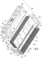
- FIG. 2 illustrates the filter element 100 in exploded form.
- the media pack 102 is generally a rectangular media pack and can take the form of pleated media, fluted media, or a simple block of media.
- the media pack 102 includes opposed first and second flow faces 114, 116 through which the fluid to be filtered generally passes.
- arrow 118 represents dirty fluid entering the filter element 100 through first flow face 114 and clean fluid exiting through second flow face 116 after the fluid has passed through the filter media of the media pack 102.
- the air flow could be opposite that of arrow 118.
- the media pack has opposed first and second sides 120, 122, that extend between the first and second flow faces 114, 116. Additionally, the media pack 102 includes opposed first and second ends 124, 126 that extend between the first and second flow faces 114, 116 and between the first and second sides 120, 122.
- the filter media pack 102 is pleated filter media.
- the media pack 102 is thus formed from a continuous sheet of filter media that has plurality of alternately oriented folds that form a plurality of pleat panels extending between the pleat folds.
- the pleat folds would form the first and second flow faces 114, 116.
- the typical pleat panel would extend the entire length L between the first and second flow faces 114, 116.
- each of the second pleat panel 129 and second to last pleat panel 131 includes a region extending between the second flow face 116 and an edge 133, 134 of the corresponding first and last pleat panels 128, 130 that is exposed, at least prior to attachment of the media support member 108 and end caps 110, 112.
- the height H of the exposed regions is greater than the length L2 of the first and last pleat panels 128, 130.
- the pleat folds 132 extend longitudinally between the first and second ends 124, 126 of the media pack 102.
- the media support member 108 extends around the first and second sides 120, 122 and the second flow face 116 to provide additional structural support to the media pack 102.
- the media support member 108 includes first and second side support panels 140, 142 that overlap, at least in part, the first and second sides 120, 122, respectively, and a flow face support panel 144 that extends across the second flow face 116.
- the first and second side support panels 140, 142 and flow face support panel 144 are all formed from a continuous piece of material.
- the entire media support member 108 may be formed from a single continuous piece of material, such as by way of molding as a continuous piece of material, machining from a single piece of material or if the media support member is formed from a fabric, providing a single piece of fabric that forms all three portions.
- the side support panels 140, 142 are connected to the flow face support panel 144.
- connection is made by hinges 146 in the form of unitary webs of material interposed between the interconnected components.
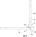
- the webs forming hinges 146 have a thickness T1 that is less than the thicknesses T2, T3 of the adjacent side support panels 140, 142 and flow face support panel 144 proximate the corresponding hinges 146 (see e.g FIG. 4 ).
- the hinges 146 form first and second grooves 150, 152 due to the reduced thickness T1 as compared to thicknesses T2, T3.
- the reduced thickness T1 allows for the media support member 108 to be formed in a flat orientation and then wrapped around the media pack 102 and particularly around first and second sides 120, 122 and second flow face 116 during assembly with the panels of the media support member 108 pivoting relative to one another via hinges 146.
- the media support member 108 maybe preformed component that is secured to the media pack 102 after formation of the media pack 102.
- the media pack support member 108 could be formed directly to the media pack 102.
- An adhesive may be applied to directly secure the media support member 108 to the filter media of the media pack 102.
- the media support member 108 will be formed from plastic materials such as polypropylene, nylon, corrugated plastic sheet, plastic mesh, possibly carboard. In some embodiments, the media support member 108 may be formed as a continuous molded piece of material.
- the media support member 108 has large apertures 156 formed there such that fluid flow through the sides 120, 122 and second flow face 116 is not significantly inhibited.
- the media support member 108 includes an imperforate border 154 that extends along peripheral edges of the media support member 108.
- the imperforate border can assist in sealing the various components of the filter element 100.
- first side support panel 140 is interposed between the first and second pleat panels 128, 129 and a portion of the second side support panel 142 is interposed between the last and second to last pleat panels 130, 131.
- the portion of the sheet of filter media forming the media pack 102 that forms the first and last pleat panels 128, 130 is folded over the corresponding one of the first and second side support panels 140, 142.
- the actual formation of these folds may occur before or after locating the media pack 102 within the media support member 108.
- first and last pleat panels 128, 130 are shorter than the second and second to last pleat panels 129, 131, a portion of each of the first and second side support panels 140, 142 is not covered by any filter media of the media pack 102. Instead, a portion of these side support panels 140, 142 proximate each of the first and second sides 120, 122 of the media pack 102 is fully exposed.
- the arrangement illustrated above of having the first and last pleat panels 128, 130 overlapping the media support member 108 facilitates improved sealing between the media pack and seal support frame 106. This prevents fluid from passing through the seal support frame 106 and particularly flow opening 107 thereof (see FIG. 1 ), from bypassing the filter media of media pack 102.
- Frame 106 may be formed from rigid plastic such as polypropylene and nylon.
- a mass of adhesive in the form of beads of adhesive 160, 162 is located between the media pack 102 and the seal support frame 106 (see FIG. 5 ).
- the adhesive 160, 162 directly engages the outer surface of pleat panels 128, 130 and the seal support frame 106. This opposed to a situation where the entire first and second sides 120, 122 of the media pack 102 were covered by the media support member 108. In that situation, the media support member 108 could inhibit a complete engagement of the adhesive with the filter media of the media pack 102 and provide possible leak paths.
- the adhesive 160, 162 need not flow around portions of the media support member 108 nor does an adhesive between the media support member 108 and the outer surfaces of the media pack need to perfectly seal the media support member 108 to the media pack to prevent undesirable leak paths between the seal support frame and the media pack 102.
- the seal support frame 106 supports housing seal 104.
- the seal 104 is an axial seal that is compressed against a radially extending flange of the seal support frame 106.
- the seal 104 may be mold-in place or a preformed seal. Further, while an axial seal is illustrated, other examples can use a radial seal.
- the seal support frame 106 needs to be sealed to the media pack 102 to prevent undesirably dirty fluid bypass around the media pack 102.
- One location with this sealing occurs is along the first and second sides 120, 122 of the media pack.
- adhesive 160, 162 provides this sealing between the support frame 106 and the media pack 102 at these locations.
- the seal support frame 106 is configured to improve the assembly of the filter element and particularly mounting the seal support frame 106 to the media pack 102.
- the seal support frame 106 is also configured to allow for increased amount of filter media in the media pack 102 as compared to the prior arrangements described above.
- the seal support frame 106 includes opposed side panels 164, 166 that extend along the first and second sides 120, 122 of the media pack 102, respectively. These side panels 164, 166 are adhesively secured to the first and second sides 120, 122 of the media pack 102 to prevent fluid bypass between the seal support frame 106 and the media pack 102, at least in part.
- the seal support frame 106 will typically be formed from molded plastic.
- the side panels 164, 166 include foldable portions 168, 170, respectively that facilitate in assembly and increased media.
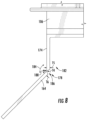
- the foldable portions 168, 170 are foldable relative to the media pack 102 as well as to fixed portions 174, 176 of a base 172 of the seal support frame 106 (see e.g. arrow 184 in FIG. 8 ).
- the fixed portions 174, 176 extend along a portion of the first and second sides, 120, 122 respectively between the first and second flow faces 114, 116, such that a portion of the media pack 102 is received within the cavity 182 formed between the fixed portions 174, 176 of the seal support frame.
- hinges 178, 180 The ability to fold the foldable portions 168, 170 is provided by hinges 178, 180.
- the hinges 178, 180 are provided by webs of material that have a reduced thickness T4 as compared to the thicknesses T5, T6 of the adjacent portions of the fixed portions 174, 176 and foldable portions 168, 170. These webs provide living hinges that allow the foldable portions 168, 170 to pivot relative to fixed portions 174, 176.
- the difference in thicknesses defines grooves 186, 188 between the inner and outer surfaces of the fixed portions 174, 176 and inner and outer surfaces of foldable portions 164, 166.
- the base 172, foldable portions 168, 170 and fixed portions 174, 176 of the seal support frame 106 are formed as a single continuous piece of material, such as machined from a single piece of material or formed by molding the components as a one-piece component.
- the foldable portions 168, 170 are folded outward, such as illustrated in FIGS. 3 and 5 .
- This provides several benefits. First, this creates a wider width mouth between the distal ends 190 of the foldable portions 168, 170 for inserting the media pack 102 between the side panels 164, 166. This allows the width W of the media pack 102 to be substantially equal to if not slightly larger than the width W1 between the fixed portions 174, 176 of the side panels 164, 166. This allows more media to be inserted into a same width W1 seal support frame.
- the seal support frame 106 is adhesively secured to the media pack 102 by an adhesive
- the foldable portions 168, 170 in the outward folded orientation defines reservoirs 192, 194 (see e.g. FIG. 5 ) between the side panels 164, 166 for receipt of masses of adhesive 160, 162 during assembly.
- the foldable portions 168, 170 can be folded towards the media pack 102. Typically, this will compress the masses of adhesive 164, 166 and cause the adhesive to spread along the sides 120, 122 of media pack 102 and particularly along the outer surfaces of first and last pleat panels 128, 130. This provides a strong attachment as well as strong seal between the seal support frame 106 and the media of the media pack 102.
- end caps 110, 112 are attached to the ends 124, 126 of the media pack 102.
- the end caps 110, 112 in the example have a main wall portion 196 and an annular wall portion 198 extending from the main wall portion 196 to define a well 200.
- An adhesive is located within the wells 200. When the ends 124, 126 of the media pack are inserted into the well, the adhesive seals the ends 124, 126 of the media pack 102.
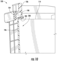
- FIG. 9 is a cross-sectional illustration illustrating the end cap 110 secured to the media pack 102.
- FIG. 9 illustrates that the ends of the side panels 164, 166 are received in the well 200 of the end cap.
- the seal support frame 106 includes a connecting wall portion 202 that extends between the side panels 164, 166 proximate the ends thereof.
- the connecting wall portion 202 extends across first flow face 114.
- Connecting wall portion 202 is secured within well 200.
- annular wall portion 198 extends around the media pack 102 and a portion of the seal support frame 106.
- the end caps 110, 112 can help secure the foldable portions 168, 170 in their proper orientation adjacent the sides of the media pack 102 as they cure.
- the foldable portions 168, 170 are folded towards the media pack 102 and the ends of the foldable portions 168, 170 are located between the annular wall portion 168 and the media pack 102 within the well 200.
Landscapes
- Chemical & Material Sciences (AREA)
- Chemical Kinetics & Catalysis (AREA)
- Filtering Of Dispersed Particles In Gases (AREA)
Claims (11)
- Un élément filtrant (100) comprenant :une cartouche de média filtrant (102) présentant une pluralité de panneaux à pli (128, 129, 130, 131), des paires de panneaux adjacents de la pluralité de panneaux à pli étant reliées entre elles par une pliure, la pluralité de panneaux à pli incluant des premier, deuxième, troisième et quatrième panneaux à pli (128, 129, 130, 131), les premier et deuxième panneaux à pli (128, 129) formant une première paire de panneaux à pli adjacents et les troisième et quatrième panneaux à pli (130, 131) formant une deuxième paire de panneaux à pli adjacents, la première paire de panneaux à pli étant à proximité d'un premier côté (120) de la cartouche de média filtrant et la deuxième paire de panneaux à pli étant à proximité d'un deuxième côté (122) opposé de la cartouche de média filtrant, la cartouche de média incluant des première et deuxième faces d'écoulement (114, 116) et premier et deuxième côtés (120, 122) opposés, les premier et deuxième côtés (120, 122) s'étendant entre les première et deuxième faces d'écoulement (114, 116) ;un organe de support de média (108) présentant un premier panneau de support de côté (140) présentant une première portion interposée entre les premier et deuxième panneaux à pli (128, 129) de la première paire de panneaux à pli adjacents, l'organe de support de média (108) présentant un deuxième panneau de support de côté (142) présentant une deuxième portion interposée entre des troisième et quatrième panneaux à pli (130, 131) de la deuxième paire de panneaux à pli adjacents, le deuxième panneau de support de côté étant adjacent au deuxième côté (122), l'organe de support de média incluant un panneau de support de face d'écoulement (144) s'étendant d'un côté à l'autre de la deuxième face d'écoulement (116) de la cartouche de média (102) entre les premier et deuxième côtés de la cartouche de média (102), le panneau de support de face d'écoulement (144) étant relié aux premier et deuxième panneaux de support de côté (140, 142), le panneau de support de face d'écoulement (144) et les premier et deuxième panneaux de support de côté (140, 142) étant formés à partir d'une pièce de matériau continue ;un cadre de support (106) assujetti à la cartouche de média filtrant (102) ; etun adhésif (160, 162) assujettissant le cadre de support (106) à la cartouche de média filtrant (102), l'adhésif (160) étant interposé entre le premier panneau à pli (128) et le cadre de support (106) avec l'adhésif qui est directement en contact avec le cadre de support (106) et directement en contact avec le premier panneau à pli (128), l'adhésif (162) étant interposé entre le troisième panneau à pli (130) et le cadre de support (106) avec l'adhésif (162) qui est directement en contact avec le cadre de support (106) et directement en contact avec le troisième panneau à pli (130).
- L'élément filtrant de la revendication 1, où le premier côté (120) est formé, au moins en partie, par le premier panneau à pli (128), le premier panneau de support de côté étant positionné, au moins en partie, entre les première et deuxième faces d'écoulement (114, 116) et adjacent au premier côté.
- L'élément filtrant de la revendication 2, où le premier panneau à pli (128) s'étend sur moins d'une longueur entière entre la première face d'écoulement (114) et la deuxième face d'écoulement (116) de telle sorte que le deuxième panneau à pli (129) forme une partie du premier côté de la cartouche de média filtrant (102).
- L'élément filtrant de la revendication 3, où le premier panneau de support de côté (140) chevauche, au moins en partie, une portion du deuxième panneau à pli (129) qui forme une partie du premier côté de la cartouche de média filtrant (102), la portion étant positionnée entre le premier panneau à pli (128) et la deuxième face d'écoulement (116).
- L'élément filtrant de la revendication 1, où le média filtrant est formé à partir d'un premier matériau et le premier panneau de support de côté (140) est formé à partir d'un deuxième matériau, le deuxième matériau étant du plastique ou du carton.
- L'élément filtrant de la revendication 1, comprenant en sus un mécanisme d'attache entre au moins un des premier et deuxième panneaux à pli (129) et le premier panneau de support de côté (140).
- L'élément filtrant de la revendication 6, où le mécanisme d'attache est du ruban adhésif double face.
- L'élément filtrant de n'importe quelle revendication précédente, où :une première bande (146) de matériau est positionnée entre et relie le panneau de support de face d'écoulement (144) et le premier panneau de support de côté (140) ; etune deuxième bande (146) de matériau est positionnée entre et relie le panneau de support de face d'écoulement (144) et le deuxième panneau de support de côté (142).
- L'élément filtrant de la revendication 8, où :la première bande (146) de matériau a une épaisseur qui est inférieure à une épaisseur du panneau de support de face d'écoulement (144) à proximité de la première bande et inférieure à une épaisseur du premier panneau de support de côté (140) à proximité de la première bande (146) ; etla deuxième bande (146) de matériau a une épaisseur qui est inférieure à une épaisseur du panneau de support de face d'écoulement (144) à proximité de la deuxième bande et inférieure à une épaisseur du deuxième panneau de support de côté (142) à proximité de la deuxième bande (146).
- Un procédé d'assemblage d'un élément filtrant (100) de n'importe quelle revendication précédente, comprenant les étapes consistant :i. à plier une portion de la cartouche de média afin de former les premier, deuxième, troisième et quatrième panneaux à pli (128, 129, 130, 131) ;ii. à positionner le premier panneau de côté (140) de l'organe de support de média (108) adjacent au premier côté de la cartouche de média (102) de telle sorte qu'une portion du premier panneau de côté (140) est positionnée entre les premier et deuxième panneaux à pli (128, 129) ;iii. à positionner le deuxième panneau de côté (142) de l'organe de support de média (108) adjacent au deuxième côté de la cartouche de média (102) de telle sorte qu'une portion du deuxième panneau de côté (142) est positionnée entre les troisième et quatrième panneaux à pli (130, 131) ;iv. à positionner la cartouche de média (102) à l'intérieur du cadre (106) avec le cadre (106) qui s'étend par-dessus le premier panneau à pli (128) de telle sorte que le premier panneau à pli (128) est placé entre le cadre (106) et le premier panneau de côté (140) de l'organe de support de média (108) ;v. à positionner la cartouche de média (102) à l'intérieur du cadre (106) avec le cadre (106) qui s'étend par-dessus le troisième panneau à pli (130) de telle sorte que le troisième panneau à pli (130) est placé entre le cadre (106) et le deuxième panneau de côté (142) de l'organe de support de média (108) ; etvi. à appliquer un cordon d'adhésif (160, 162) entre le cadre (106) et le premier panneau à pli (128) de la cartouche de média (102) de telle sorte que l'adhésif (160) est directement en contact avec une surface interne du cadre (106) et une surface externe du premier panneau à pli (128) et à appliquer l'adhésif (160, 162) entre le cadre (106) et le troisième panneau à pli (130) de la cartouche de média (102) de telle sorte que l'adhésif (162) est directement en contact avec une surface interne du cadre (106) et une surface externe du troisième panneau à pli (130).
- Le procédé de la revendication 10, où le cadre (106) inclut un panneau de côté (164) qui s'étend à partir d'une portion de corps annulaire (172) du cadre (106), le panneau de côté (164) s'étendant par-dessus le premier côté de la cartouche de média (102), l'adhésif (160) étant directement en prise avec une surface interne du panneau de côté (164).
Priority Applications (1)
| Application Number | Priority Date | Filing Date | Title |
|---|---|---|---|
| EP24216576.9A EP4512506B1 (fr) | 2020-07-09 | 2021-07-07 | Châssis pour filtres doté d'un rabat de scellement pliable |
Applications Claiming Priority (4)
| Application Number | Priority Date | Filing Date | Title |
|---|---|---|---|
| US202062705647P | 2020-07-09 | 2020-07-09 | |
| US202163136533P | 2021-01-12 | 2021-01-12 | |
| US17/353,253 US11992796B2 (en) | 2020-07-09 | 2021-06-21 | Filter frame with foldable sealing flap |
| EP21184190.3A EP3936215B1 (fr) | 2020-07-09 | 2021-07-07 | Châssis pour filtres doté d'un rabat de scellement pliable |
Related Parent Applications (2)
| Application Number | Title | Priority Date | Filing Date |
|---|---|---|---|
| EP21184190.3A Division EP3936215B1 (fr) | 2020-07-09 | 2021-07-07 | Châssis pour filtres doté d'un rabat de scellement pliable |
| EP21184190.3A Division-Into EP3936215B1 (fr) | 2020-07-09 | 2021-07-07 | Châssis pour filtres doté d'un rabat de scellement pliable |
Related Child Applications (1)
| Application Number | Title | Priority Date | Filing Date |
|---|---|---|---|
| EP24216576.9A Division EP4512506B1 (fr) | 2020-07-09 | 2021-07-07 | Châssis pour filtres doté d'un rabat de scellement pliable |
Publications (2)
| Publication Number | Publication Date |
|---|---|
| EP4260929A1 EP4260929A1 (fr) | 2023-10-18 |
| EP4260929B1 true EP4260929B1 (fr) | 2025-01-01 |
Family
ID=76829412
Family Applications (3)
| Application Number | Title | Priority Date | Filing Date |
|---|---|---|---|
| EP24216576.9A Active EP4512506B1 (fr) | 2020-07-09 | 2021-07-07 | Châssis pour filtres doté d'un rabat de scellement pliable |
| EP21184190.3A Active EP3936215B1 (fr) | 2020-07-09 | 2021-07-07 | Châssis pour filtres doté d'un rabat de scellement pliable |
| EP23190638.9A Active EP4260929B1 (fr) | 2020-07-09 | 2021-07-07 | Châssis pour filtres doté d'un rabat de scellement pliable |
Family Applications Before (2)
| Application Number | Title | Priority Date | Filing Date |
|---|---|---|---|
| EP24216576.9A Active EP4512506B1 (fr) | 2020-07-09 | 2021-07-07 | Châssis pour filtres doté d'un rabat de scellement pliable |
| EP21184190.3A Active EP3936215B1 (fr) | 2020-07-09 | 2021-07-07 | Châssis pour filtres doté d'un rabat de scellement pliable |
Country Status (2)
| Country | Link |
|---|---|
| US (3) | US11992796B2 (fr) |
| EP (3) | EP4512506B1 (fr) |
Families Citing this family (4)
| Publication number | Priority date | Publication date | Assignee | Title |
|---|---|---|---|---|
| US11992796B2 (en) * | 2020-07-09 | 2024-05-28 | Baldwin Filters, Inc. | Filter frame with foldable sealing flap |
| USD1094680S1 (en) * | 2022-03-23 | 2025-09-23 | Valdek Jakobczyk | Engine air filter |
| US20240042361A1 (en) * | 2022-08-06 | 2024-02-08 | Baldwin Filters, Inc. | Embedding variable slit width embossed filter media packs |
| WO2025159804A1 (fr) * | 2024-01-22 | 2025-07-31 | Baldwin Filters, Inc. | Panneau de support intérieur |
Family Cites Families (22)
| Publication number | Priority date | Publication date | Assignee | Title |
|---|---|---|---|---|
| US3712033A (en) | 1971-06-01 | 1973-01-23 | Donaldson Co Inc | Air cleaner with hinged side walls |
| BE788210A (fr) | 1971-09-16 | 1973-02-28 | Pall Corp | Boite filtrante |
| US3992173A (en) | 1975-04-24 | 1976-11-16 | Korhumel Industries, Inc. | Air filter and method of making same |
| CA1054952A (fr) | 1975-12-01 | 1979-05-22 | Bernard A. Latakas | Filtre d'air compact avec bati tubulaire |
| US4135900A (en) | 1977-05-31 | 1979-01-23 | American Air Filter Company, Inc. | Gas filter device |
| US4617122A (en) * | 1984-08-01 | 1986-10-14 | Donaldson Company, Inc. | Crimp seal pleated filter assembly |
| US6159318A (en) | 1998-10-21 | 2000-12-12 | Aaf International, Inc. | Method for forming fibrous filter media, filter units and product |
| US6406509B1 (en) * | 1999-07-01 | 2002-06-18 | 3M Innovative Properties Company | Extruded profile filter framing |
| DE10013301B4 (de) | 2000-03-17 | 2007-04-05 | Carl Freudenberg Kg | Filtereinsatz |
| US7320720B2 (en) | 2005-10-17 | 2008-01-22 | Kirk Ticknor | Interlocking filtration device |
| US7691165B1 (en) | 2006-06-12 | 2010-04-06 | Frank Hammes | Fluid filter frame system and method |
| DE202007004794U1 (de) * | 2007-03-30 | 2008-07-31 | Mann + Hummel Gmbh | Filterelement |
| DE102009042588B4 (de) * | 2008-12-15 | 2023-05-04 | Mann+Hummel Gmbh | Filtersystem mit wenigstens einem Rahmenelement an seinem Längsrand |
| CA2665541C (fr) * | 2009-04-28 | 2017-04-11 | Clarcor Air Filtration Products, Inc. | Panneau filtrant |
| CA2665530C (fr) * | 2009-04-28 | 2017-04-11 | Clarcor Air Filtration Products, Inc. | Panneau filtrant |
| CN102421504B (zh) | 2009-05-14 | 2015-05-20 | 曼·胡默尔有限公司 | 用于加工尤其矩形的用于流体的扁平过滤部件的方法、过滤部件和具有过滤部件的过滤装置 |
| US8382874B2 (en) | 2010-06-28 | 2013-02-26 | Lennox Industries Inc. | Air filter having dimensional extending tabs |
| US8992650B2 (en) * | 2012-10-19 | 2015-03-31 | American Air Filter Company, Inc. | Air filter with tensile support member |
| US9724635B2 (en) | 2013-03-14 | 2017-08-08 | Bladwin Filters, Inc. | Rectangular stacked fluted filter cartridge |
| CA2885565C (fr) * | 2014-03-24 | 2022-07-12 | 3M Innovative Properties Company | Filtre a air encadre dote d'un joint emboitable integre |
| US10357731B2 (en) | 2016-12-20 | 2019-07-23 | Baldwin Filters, Inc. | Filter with preformed end caps having notch feature |
| US11992796B2 (en) * | 2020-07-09 | 2024-05-28 | Baldwin Filters, Inc. | Filter frame with foldable sealing flap |
-
2021
- 2021-06-21 US US17/353,253 patent/US11992796B2/en active Active
- 2021-07-07 EP EP24216576.9A patent/EP4512506B1/fr active Active
- 2021-07-07 EP EP21184190.3A patent/EP3936215B1/fr active Active
- 2021-07-07 EP EP23190638.9A patent/EP4260929B1/fr active Active
-
2024
- 2024-04-24 US US18/644,385 patent/US12318723B2/en active Active
-
2025
- 2025-05-12 US US19/205,408 patent/US20250269309A1/en active Pending
Also Published As
| Publication number | Publication date |
|---|---|
| US20240269591A1 (en) | 2024-08-15 |
| US11992796B2 (en) | 2024-05-28 |
| EP3936215A1 (fr) | 2022-01-12 |
| US12318723B2 (en) | 2025-06-03 |
| US20220008853A1 (en) | 2022-01-13 |
| EP4512506B1 (fr) | 2026-03-25 |
| EP4260929A1 (fr) | 2023-10-18 |
| EP4512506A1 (fr) | 2025-02-26 |
| EP3936215B1 (fr) | 2023-10-18 |
| US20250269309A1 (en) | 2025-08-28 |
Similar Documents
| Publication | Publication Date | Title |
|---|---|---|
| EP4512506B1 (fr) | Châssis pour filtres doté d'un rabat de scellement pliable | |
| US8696782B2 (en) | Filter device, especially air filter for an internal combustion engine | |
| AU2005301266B2 (en) | Filter element with canted seal support | |
| US7708796B2 (en) | Axial flow filter element | |
| US8062404B2 (en) | Filter insert | |
| EP3559436B1 (fr) | Filtre doté de capuchons d'extrémité préformés comprenant un élément d'encoche | |
| US20140290194A1 (en) | Filter Device, Especially an Air Filter | |
| US20240408527A1 (en) | Flat-filter filter element with at least two filter medium bodies, filter system and use of flat-filter filter element | |
| CN119998022A (zh) | 过滤元件和过滤装置 | |
| EP4221865B1 (fr) | Elément filtrant | |
| US11958007B2 (en) | Filter element | |
| US20250058263A1 (en) | Filter with shield features | |
| US20260097348A1 (en) | Flat-filter filter element having at least two filter-material bodies, filter system, and use of a flat-filter filter element | |
| WO2025159804A1 (fr) | Panneau de support intérieur | |
| WO2022109017A1 (fr) | Filtre doté d'éléments de protection |
Legal Events
| Date | Code | Title | Description |
|---|---|---|---|
| PUAI | Public reference made under article 153(3) epc to a published international application that has entered the european phase |
Free format text: ORIGINAL CODE: 0009012 |
|
| STAA | Information on the status of an ep patent application or granted ep patent |
Free format text: STATUS: THE APPLICATION HAS BEEN PUBLISHED |
|
| AC | Divisional application: reference to earlier application |
Ref document number: 3936215 Country of ref document: EP Kind code of ref document: P |
|
| AK | Designated contracting states |
Kind code of ref document: A1 Designated state(s): AL AT BE BG CH CY CZ DE DK EE ES FI FR GB GR HR HU IE IS IT LI LT LU LV MC MK MT NL NO PL PT RO RS SE SI SK SM TR |
|
| STAA | Information on the status of an ep patent application or granted ep patent |
Free format text: STATUS: REQUEST FOR EXAMINATION WAS MADE |
|
| P01 | Opt-out of the competence of the unified patent court (upc) registered |
Effective date: 20240408 |
|
| 17P | Request for examination filed |
Effective date: 20240416 |
|
| RBV | Designated contracting states (corrected) |
Designated state(s): AL AT BE BG CH CY CZ DE DK EE ES FI FR GB GR HR HU IE IS IT LI LT LU LV MC MK MT NL NO PL PT RO RS SE SI SK SM TR |
|
| GRAP | Despatch of communication of intention to grant a patent |
Free format text: ORIGINAL CODE: EPIDOSNIGR1 |
|
| STAA | Information on the status of an ep patent application or granted ep patent |
Free format text: STATUS: GRANT OF PATENT IS INTENDED |
|
| INTG | Intention to grant announced |
Effective date: 20240722 |
|
| GRAS | Grant fee paid |
Free format text: ORIGINAL CODE: EPIDOSNIGR3 |
|
| GRAA | (expected) grant |
Free format text: ORIGINAL CODE: 0009210 |
|
| STAA | Information on the status of an ep patent application or granted ep patent |
Free format text: STATUS: THE PATENT HAS BEEN GRANTED |
|
| AC | Divisional application: reference to earlier application |
Ref document number: 3936215 Country of ref document: EP Kind code of ref document: P |
|
| AK | Designated contracting states |
Kind code of ref document: B1 Designated state(s): AL AT BE BG CH CY CZ DE DK EE ES FI FR GB GR HR HU IE IS IT LI LT LU LV MC MK MT NL NO PL PT RO RS SE SI SK SM TR |
|
| REG | Reference to a national code |
Ref country code: GB Ref legal event code: FG4D |
|
| REG | Reference to a national code |
Ref country code: DE Ref legal event code: R096 Ref document number: 602021024533 Country of ref document: DE |
|
| REG | Reference to a national code |
Ref country code: CH Ref legal event code: EP |
|
| REG | Reference to a national code |
Ref country code: IE Ref legal event code: FG4D |
|
| REG | Reference to a national code |
Ref country code: LT Ref legal event code: MG9D |
|
| REG | Reference to a national code |
Ref country code: NL Ref legal event code: MP Effective date: 20250101 |
|
| REG | Reference to a national code |
Ref country code: AT Ref legal event code: MK05 Ref document number: 1755668 Country of ref document: AT Kind code of ref document: T Effective date: 20250101 |
|
| PG25 | Lapsed in a contracting state [announced via postgrant information from national office to epo] |
Ref country code: NL Free format text: LAPSE BECAUSE OF FAILURE TO SUBMIT A TRANSLATION OF THE DESCRIPTION OR TO PAY THE FEE WITHIN THE PRESCRIBED TIME-LIMIT Effective date: 20250101 |
|
| PG25 | Lapsed in a contracting state [announced via postgrant information from national office to epo] |
Ref country code: FI Free format text: LAPSE BECAUSE OF FAILURE TO SUBMIT A TRANSLATION OF THE DESCRIPTION OR TO PAY THE FEE WITHIN THE PRESCRIBED TIME-LIMIT Effective date: 20250101 |
|
| PG25 | Lapsed in a contracting state [announced via postgrant information from national office to epo] |
Ref country code: PL Free format text: LAPSE BECAUSE OF FAILURE TO SUBMIT A TRANSLATION OF THE DESCRIPTION OR TO PAY THE FEE WITHIN THE PRESCRIBED TIME-LIMIT Effective date: 20250101 |
|
| PG25 | Lapsed in a contracting state [announced via postgrant information from national office to epo] |
Ref country code: ES Free format text: LAPSE BECAUSE OF FAILURE TO SUBMIT A TRANSLATION OF THE DESCRIPTION OR TO PAY THE FEE WITHIN THE PRESCRIBED TIME-LIMIT Effective date: 20250101 |
|
| PG25 | Lapsed in a contracting state [announced via postgrant information from national office to epo] |
Ref country code: IS Free format text: LAPSE BECAUSE OF FAILURE TO SUBMIT A TRANSLATION OF THE DESCRIPTION OR TO PAY THE FEE WITHIN THE PRESCRIBED TIME-LIMIT Effective date: 20250501 Ref country code: NO Free format text: LAPSE BECAUSE OF FAILURE TO SUBMIT A TRANSLATION OF THE DESCRIPTION OR TO PAY THE FEE WITHIN THE PRESCRIBED TIME-LIMIT Effective date: 20250401 |
|
| PG25 | Lapsed in a contracting state [announced via postgrant information from national office to epo] |
Ref country code: HR Free format text: LAPSE BECAUSE OF FAILURE TO SUBMIT A TRANSLATION OF THE DESCRIPTION OR TO PAY THE FEE WITHIN THE PRESCRIBED TIME-LIMIT Effective date: 20250101 |
|
| PG25 | Lapsed in a contracting state [announced via postgrant information from national office to epo] |
Ref country code: LV Free format text: LAPSE BECAUSE OF FAILURE TO SUBMIT A TRANSLATION OF THE DESCRIPTION OR TO PAY THE FEE WITHIN THE PRESCRIBED TIME-LIMIT Effective date: 20250101 Ref country code: PT Free format text: LAPSE BECAUSE OF FAILURE TO SUBMIT A TRANSLATION OF THE DESCRIPTION OR TO PAY THE FEE WITHIN THE PRESCRIBED TIME-LIMIT Effective date: 20250502 |
|
| PG25 | Lapsed in a contracting state [announced via postgrant information from national office to epo] |
Ref country code: BG Free format text: LAPSE BECAUSE OF FAILURE TO SUBMIT A TRANSLATION OF THE DESCRIPTION OR TO PAY THE FEE WITHIN THE PRESCRIBED TIME-LIMIT Effective date: 20250101 Ref country code: GR Free format text: LAPSE BECAUSE OF FAILURE TO SUBMIT A TRANSLATION OF THE DESCRIPTION OR TO PAY THE FEE WITHIN THE PRESCRIBED TIME-LIMIT Effective date: 20250402 |
|
| PG25 | Lapsed in a contracting state [announced via postgrant information from national office to epo] |
Ref country code: AT Free format text: LAPSE BECAUSE OF FAILURE TO SUBMIT A TRANSLATION OF THE DESCRIPTION OR TO PAY THE FEE WITHIN THE PRESCRIBED TIME-LIMIT Effective date: 20250101 |
|
| PG25 | Lapsed in a contracting state [announced via postgrant information from national office to epo] |
Ref country code: CZ Free format text: LAPSE BECAUSE OF FAILURE TO SUBMIT A TRANSLATION OF THE DESCRIPTION OR TO PAY THE FEE WITHIN THE PRESCRIBED TIME-LIMIT Effective date: 20250101 |
|
| PG25 | Lapsed in a contracting state [announced via postgrant information from national office to epo] |
Ref country code: SE Free format text: LAPSE BECAUSE OF FAILURE TO SUBMIT A TRANSLATION OF THE DESCRIPTION OR TO PAY THE FEE WITHIN THE PRESCRIBED TIME-LIMIT Effective date: 20250101 |
|
| REG | Reference to a national code |
Ref country code: DE Ref legal event code: R097 Ref document number: 602021024533 Country of ref document: DE |
|
| PG25 | Lapsed in a contracting state [announced via postgrant information from national office to epo] |
Ref country code: SM Free format text: LAPSE BECAUSE OF FAILURE TO SUBMIT A TRANSLATION OF THE DESCRIPTION OR TO PAY THE FEE WITHIN THE PRESCRIBED TIME-LIMIT Effective date: 20250101 |
|
| PG25 | Lapsed in a contracting state [announced via postgrant information from national office to epo] |
Ref country code: DK Free format text: LAPSE BECAUSE OF FAILURE TO SUBMIT A TRANSLATION OF THE DESCRIPTION OR TO PAY THE FEE WITHIN THE PRESCRIBED TIME-LIMIT Effective date: 20250101 |
|
| PGFP | Annual fee paid to national office [announced via postgrant information from national office to epo] |
Ref country code: DE Payment date: 20250729 Year of fee payment: 5 |
|
| PG25 | Lapsed in a contracting state [announced via postgrant information from national office to epo] |
Ref country code: IT Free format text: LAPSE BECAUSE OF FAILURE TO SUBMIT A TRANSLATION OF THE DESCRIPTION OR TO PAY THE FEE WITHIN THE PRESCRIBED TIME-LIMIT Effective date: 20250101 |
|
| PGFP | Annual fee paid to national office [announced via postgrant information from national office to epo] |
Ref country code: GB Payment date: 20250728 Year of fee payment: 5 |
|
| PG25 | Lapsed in a contracting state [announced via postgrant information from national office to epo] |
Ref country code: EE Free format text: LAPSE BECAUSE OF FAILURE TO SUBMIT A TRANSLATION OF THE DESCRIPTION OR TO PAY THE FEE WITHIN THE PRESCRIBED TIME-LIMIT Effective date: 20250101 |
|
| PG25 | Lapsed in a contracting state [announced via postgrant information from national office to epo] |
Ref country code: RO Free format text: LAPSE BECAUSE OF FAILURE TO SUBMIT A TRANSLATION OF THE DESCRIPTION OR TO PAY THE FEE WITHIN THE PRESCRIBED TIME-LIMIT Effective date: 20250101 |
|
| PG25 | Lapsed in a contracting state [announced via postgrant information from national office to epo] |
Ref country code: SK Free format text: LAPSE BECAUSE OF FAILURE TO SUBMIT A TRANSLATION OF THE DESCRIPTION OR TO PAY THE FEE WITHIN THE PRESCRIBED TIME-LIMIT Effective date: 20250101 |
|
| PLBE | No opposition filed within time limit |
Free format text: ORIGINAL CODE: 0009261 |
|
| STAA | Information on the status of an ep patent application or granted ep patent |
Free format text: STATUS: NO OPPOSITION FILED WITHIN TIME LIMIT |
|
| REG | Reference to a national code |
Ref country code: CH Ref legal event code: L10 Free format text: ST27 STATUS EVENT CODE: U-0-0-L10-L00 (AS PROVIDED BY THE NATIONAL OFFICE) Effective date: 20251112 |
|
| 26N | No opposition filed |
Effective date: 20251002 |
|
| REG | Reference to a national code |
Ref country code: CH Ref legal event code: H13 Free format text: ST27 STATUS EVENT CODE: U-0-0-H10-H13 (AS PROVIDED BY THE NATIONAL OFFICE) Effective date: 20260224 |
|
| PG25 | Lapsed in a contracting state [announced via postgrant information from national office to epo] |
Ref country code: LU Free format text: LAPSE BECAUSE OF NON-PAYMENT OF DUE FEES Effective date: 20250707 |
|
| REG | Reference to a national code |
Ref country code: BE Ref legal event code: MM Effective date: 20250731 |
|
| PG25 | Lapsed in a contracting state [announced via postgrant information from national office to epo] |
Ref country code: BE Free format text: LAPSE BECAUSE OF NON-PAYMENT OF DUE FEES Effective date: 20250731 |
|
| PG25 | Lapsed in a contracting state [announced via postgrant information from national office to epo] |
Ref country code: FR Free format text: LAPSE BECAUSE OF NON-PAYMENT OF DUE FEES Effective date: 20250731 |
|
| PG25 | Lapsed in a contracting state [announced via postgrant information from national office to epo] |
Ref country code: CH Free format text: LAPSE BECAUSE OF NON-PAYMENT OF DUE FEES Effective date: 20250731 |