EP4260962A1 - Dispositif de mise en forme d'angle - Google Patents
Dispositif de mise en forme d'angle Download PDFInfo
- Publication number
- EP4260962A1 EP4260962A1 EP22729010.3A EP22729010A EP4260962A1 EP 4260962 A1 EP4260962 A1 EP 4260962A1 EP 22729010 A EP22729010 A EP 22729010A EP 4260962 A1 EP4260962 A1 EP 4260962A1
- Authority
- EP
- European Patent Office
- Prior art keywords
- cutter head
- wire
- shaping
- support platform
- guide wire
- Prior art date
- Legal status (The legal status is an assumption and is not a legal conclusion. Google has not performed a legal analysis and makes no representation as to the accuracy of the status listed.)
- Pending
Links
- 238000007493 shaping process Methods 0.000 title claims abstract description 68
- 238000005452 bending Methods 0.000 claims abstract description 45
- 238000003825 pressing Methods 0.000 claims abstract description 37
- 238000000034 method Methods 0.000 claims abstract description 12
- 239000000758 substrate Substances 0.000 claims description 26
- 239000000463 material Substances 0.000 claims description 12
- 239000000178 monomer Substances 0.000 claims description 6
- 238000010586 diagram Methods 0.000 description 7
- 230000008569 process Effects 0.000 description 7
- 239000002184 metal Substances 0.000 description 6
- 238000001356 surgical procedure Methods 0.000 description 5
- 238000006073 displacement reaction Methods 0.000 description 4
- 239000007769 metal material Substances 0.000 description 4
- 230000009471 action Effects 0.000 description 2
- 239000000956 alloy Substances 0.000 description 2
- 239000011248 coating agent Substances 0.000 description 2
- 238000000576 coating method Methods 0.000 description 2
- 238000004519 manufacturing process Methods 0.000 description 2
- 238000002360 preparation method Methods 0.000 description 2
- 229910045601 alloy Inorganic materials 0.000 description 1
- 238000013130 cardiovascular surgery Methods 0.000 description 1
- 230000001684 chronic effect Effects 0.000 description 1
- 238000004512 die casting Methods 0.000 description 1
- 230000036541 health Effects 0.000 description 1
- 238000003780 insertion Methods 0.000 description 1
- 230000037431 insertion Effects 0.000 description 1
- 229910052755 nonmetal Inorganic materials 0.000 description 1
- 230000035515 penetration Effects 0.000 description 1
- 229920002994 synthetic fiber Polymers 0.000 description 1
- 238000002560 therapeutic procedure Methods 0.000 description 1
- 230000002792 vascular Effects 0.000 description 1
- 238000011179 visual inspection Methods 0.000 description 1
Images


Classifications
-
- A—HUMAN NECESSITIES
- A61—MEDICAL OR VETERINARY SCIENCE; HYGIENE
- A61M—DEVICES FOR INTRODUCING MEDIA INTO, OR ONTO, THE BODY; DEVICES FOR TRANSDUCING BODY MEDIA OR FOR TAKING MEDIA FROM THE BODY; DEVICES FOR PRODUCING OR ENDING SLEEP OR STUPOR
- A61M25/00—Catheters; Hollow probes
- A61M25/01—Introducing, guiding, advancing, emplacing or holding catheters
- A61M25/09—Guide wires
- A61M25/0905—Guide wires extendable, e.g. mechanisms for extension
-
- B—PERFORMING OPERATIONS; TRANSPORTING
- B21—MECHANICAL METAL-WORKING WITHOUT ESSENTIALLY REMOVING MATERIAL; PUNCHING METAL
- B21F—WORKING OR PROCESSING OF METAL WIRE
- B21F1/00—Bending wire other than coiling; Straightening wire
-
- A—HUMAN NECESSITIES
- A61—MEDICAL OR VETERINARY SCIENCE; HYGIENE
- A61M—DEVICES FOR INTRODUCING MEDIA INTO, OR ONTO, THE BODY; DEVICES FOR TRANSDUCING BODY MEDIA OR FOR TAKING MEDIA FROM THE BODY; DEVICES FOR PRODUCING OR ENDING SLEEP OR STUPOR
- A61M25/00—Catheters; Hollow probes
- A61M25/01—Introducing, guiding, advancing, emplacing or holding catheters
- A61M25/09—Guide wires
- A61M2025/09108—Methods for making a guide wire
-
- A—HUMAN NECESSITIES
- A61—MEDICAL OR VETERINARY SCIENCE; HYGIENE
- A61M—DEVICES FOR INTRODUCING MEDIA INTO, OR ONTO, THE BODY; DEVICES FOR TRANSDUCING BODY MEDIA OR FOR TAKING MEDIA FROM THE BODY; DEVICES FOR PRODUCING OR ENDING SLEEP OR STUPOR
- A61M25/00—Catheters; Hollow probes
- A61M25/01—Introducing, guiding, advancing, emplacing or holding catheters
- A61M25/09—Guide wires
- A61M2025/09116—Design of handles or shafts or gripping surfaces thereof for manipulating guide wires
Definitions
- the present invention relates to the technical field of instruments, and in particular, to a device for providing angular shaping in the technical field of a medical device.
- filamentary materials of a plurality of metal materials or non-metallic materials often require to be bent at an angle to form a shape with a certain length of a bending head for ease of use.
- most of tools for angle bending in the prior art are used for a metal with a certain degree of thickness.
- the filamentary material is usually bent at an angle manually, which leads to a deviation in a bending angle and is not accurate.
- a "guide wire"-shaped material is often used in a surgery or an interventional therapy to evacuate or fix certain tissues. These guide wires have usually a diameter of less than 1 mm and have to be bent at an accurate angle at one end to achieve their function.
- CTO chronic total occlusion
- a clinician generally shapes the guide wire based on his experience, and is unable to accurately grasp a shaping length and angle, which can easily lead to failure of vascular evacuation during the surgery, causing a certain impact on the quality of the surgery and seriously threatening the health and life of a patient.
- the present invention provides a device for shaping an angle, which can quickly and reliably provide a guide wire with a certain bending angle as required.
- the guide wire described in the present invention includes: a metal wire, a metal wire containing a coating, and a hollow metal wire, where the metal includes alloy; a non-metallic wire, a non-metallic wire containing a coating, and a hollow non-metallic wire, where the non-metal is a hard non-metallic material with certain ductility capable of performing certain penetration functions; and a guiding wire (a guiding line) which is a tool configured as puncture, insertion of a catheter, and evacuation.
- the guide wire acts as a guide and support for the catheter and helps the catheter enter a lumen or a target site.
- the entry direction of the guide wire is set as from front to back.
- a front side and a back side mentioned in a text are understood as follows: a side close to the wire guide guided before the guide wire is entered is the front side, and a side close to the bending head of the guide wire during a bending process is the back side.
- the present invention first provides a device for shaping an angle, including a support platform and an angled cutter head.
- the support platform serves as a support surface for placing the guide wire.
- the angled cutter head is configured to bend the guide wire at an accurate angle.
- the guide wire is placed on the support platform, extending a certain bending length.
- the guide wire is pressed down with an angled cutter head of which the bottom surface is provided with a certain angle.
- the guide wire of which one end has an angle of required accuracy is prepared.
- the angled cutter head of the present invention is a three-dimensional structure (a cutter head body) with a specific angled bottom surface. Further, the angled bottom surface can consist of one or more different inclined surfaces (small cutter heads). Each of the inclined surfaces (the small cutter heads) has different inclined angles. Therefore, the wire guide heads with different bending angles can be bent during a wire pressing process. Preferably, the inclined surfaces are distributed continuously or at intervals.
- the small cutter head described in the present invention can have the following structures: one or more bosses are provided on the bottom surface of the main body of the cutter head along the side thereof. the vertical side of the boss opposite to the side of the support platform is prepared as the inclined surface. The inclined surface is at a certain angle to the side of the support platform.
- the angled cutter head is fixedly connected to the support platform via a connecting device.
- the angled cutter head can move up and down to bend the guide wire under the constraint of the connecting device.
- the connecting device is preferably a spring connecting device.
- the spring connecting device is structured in such a way that the two ends of the angled cutter head is connected to the support platform via a first spring.
- the two ends of the angled cutter head are provided with a hollow cavity.
- a first spring is provided in the hollow cavity.
- the bottom of the first spring is fixedly connected to the support platform.
- the first spring is sleeved on a guide post. One end of the guide post is fixed to the support platform, and the other end of the guide post passes through the angled cutter head and is a free end.
- the device for shaping the angle of the present invention is provided with a wire guide entry platform on the support platform.
- the wire guide entry platform is provided thereon with a wire guide entry hole for guiding the wire guide to be below the angled cutter head.
- the guide wire entry hole is provided on one side of the support platform.
- one or the plurality of guide wire entry holes can be arranged.
- the number of the guide guide entry holes matches that of the small cutter heads of the angled cutter head.
- the size of the aperture of the guide wire entry hole is matched with the thickness of a required bending material according to actual needs.
- the lowest point of a wire exit at the end of the guide wire entry hole is tangential with the side of the support platform to ensure that the upper side of the support platform can play a support role after the guide wire enters the guide wire entry hole.
- the device for shaping the angle of the present invention is provided with a wire pressing device.
- the wire pressing device is provided on the angled cutter head in order not to displace the guide wire during the bending process.
- the wire pressing device is the bottom side of the angled cutter head.
- the angled cutter head goes down.
- the bottom side of the angled cutter head cooperates with the upper side of the support platform to fix the guide wire.
- the small cutter head located on the lower side of the main body of the angled cutter head is adjacent to the rear side of the support platform and is on the lower side of the rear side of the main body of the angled cutter head.
- An inclined angle is formed between the inclined surface of the small cutter head and the rear side of the support platform when the angled cutter head is pressed down.
- the angled cutter head is connected to the wire pressing device via the second spring device.
- the main body of the angled cutter head is provided with an inner cavity.
- a pair of second springs are provided in the inner cavity.
- One end of the second spring is fixed with the cutter head body, and the other end of the second spring is fixed with the wire pressing device.
- the lower side of the wire pressing device is lower than the lower side of the cutter head body in the natural state of the second spring.
- the inner cavity is provided in the middle of the angled cutter head.
- the second spring is provided symmetrically along the midline of the inner cavity.
- the wire pressing device is a three-dimensional structure of which the bottom surface is a plane.
- the device for shaping the angle of the present invention is provided with a limit device for precisely defining the bending length of the guide wire.
- a limit device is provided on the rear side of the support platform.
- the limit device is provided on the rear side of the angled cutter head and the opposite side of the guide wire entry hole.
- a distance between the front side (a limit surface) of the limit device and the rear side of the support platform is called as a traveling length.
- the traveling length determines the bending length of the guide wire.
- the structure of the limit device is adjusted or different limit devices are arranged so that different traveling lengths can be set at the same time to control the head bending length of different guide wires.
- the device for shaping the angle of the present invention can further be provided with a substrate.
- the substrate is configured to carry the device for shaping the angle.
- the device for shaping the angle is removably connected to the substrate.
- the connection mode includes but is not limited to: a bolt, a screw connection, snap-fitting, etc.
- the substrate is provided with a mounting structure of the device for shaping the angle.
- the mounting structure includes but is not limited to: a screw hole, a snap-fitting structure, etc.
- one or more devices for shaping the angles are simultaneously provided on the substrate.
- the device for shaping the angle can have the same or different shaping angles and shaping lengths.
- the limit device is arranged on the substrate.
- the substrate is arranged on the rear side of the angled cutter head and the opposite side of the guide wire entry hole. There is a traveling length between the substrate and the rear side of the support platform.
- the device for shaping the angle can be easily combined with the substrate in use.
- the limit device can be integrally provided with the support platform.
- each of the devices for shaping the angles and the limit device form one monomer of the device for shaping the angle.
- the monomer of each of the devices for shaping the angles can has different traveling lengths, i.e., to cope with the demand for different bending angles under a single traveling length. Therefore, the device for shaping the angle formed by the plurality of monomers of the device for shaping the angle can cope with the task of bending the guide wires with requirements of different traveling lengths and different bending angles.
- the present invention provides the device for shaping the angle.
- the device for shaping the angle can be configured to bend various types of wire guide ends.
- a user can adjust the traveling length and the specifications of the angled cutter head according to actual needs. According to the properties and thickness of a material to be bent, the size and the manufacturing material of the device for shaping the angle are adjusted to apply the bending material.
- a preferred material for the preparation of the device for shaping the angle of the present invention includes a synthetic material, an alloy material or a metallic material and so on.
- the present invention provides a method for shaping a device for shaping an angle, including the following steps: setting a guide wire entry hole at one side (a front side) of the support platform; setting a plurality of guide wire entry holes; cooperating, by the size of the aperture of the guide wire entry hole, with the thickness of the material to be bent according to actual needs, and the lowest point of the wire exit at the end of the guide wire entry hole being tangential with the upper side of the support platform to ensure that the upper side of the support platform can play a support role after the guide wire enters the guide wire entry hole.
- the support platform is connected to the angled cutter head via a connecting device together.
- the support platform can be connected to the angled cutter head together via a spring connecting device so that the angled cutter head can move up and down relative to the support platform.
- the angled cutter head includes a cutter head body and an inclined surface cutter head.
- the vertical side of the inclined surface cutter head adjacent to the support platform is provided as a slope surface as the cutter head.
- the slope surface cooperates with the upper side of the support platform during the sinking process of the angled cutter head to complete the task of bending the guide wire.
- one limit device that cooperates with the other side (the rear side) of the substrate or the support platform needs to be prepared.
- the limit device is fixed to the rear side of the substrate or the support platform.
- a distance between the limit device and the rear side of the support platform is the traveling length, which is the bending length.
- the traveling length includes any desired length such as: 0.5 mm, 1 mm, 1.2 mm, 1.5 mm, 2 mm, 3 mm, or 5 mm.
- the cutter head angle of the angled cutter head can be any desired angle, such as 15 degrees, 20 degrees, 25 degrees, 30 degrees, 40 degrees, 45 degrees, 50 degrees, 70 degrees, or 90 degrees.
- the limit device can be moved back and forth.
- the limit device can be withdrawn (or extruded outward) when the angled cutter head is pressed down to form, ensuring that the end of the guide wire is not blocked when the guide wire is bent at an angle.
- the technical solutions used in the present invention can easily and quickly bend metal guide wires or other materials with a certain degree of toughness and ductility.
- the structure of the device can be both small and light, as well as large. Pressure can be provided manually or via a mechanical force.
- the device for shaping the angle provided by the present invention can accurately bend the guide wire at an angle and a length, and can prepare guide wires with different bending lengths and bending angles according to actual needs.
- a device for shaping an angle includes a support platform 2 and an angled cutter head 31.
- the support platform 2 is used as the lower support surface of a guide wire.
- the angled cutter head 31 is configured to bend the guide wire.
- the guide wire is placed on the support platform 2, extends a certain bending length, and pressed down against the side of the support platform with the angled cutter head 31 with a certain angle on the bottom side thereof.
- the angled cutter head 31 includes a first stepped platform 10 and a second stepped platform 11.
- the second stepped platform 11 and the vertical side adjacent to the support platform 2 are provided as a certain angle of a slope surface as the cutter head.
- the bottom surface 10 of the first stepped platform fits the upper side of the support platform 2 to fix the guide wire.
- the upper cutter head part of the second stepped platform 11 is pressed down to complete the task of bending the guide wire.
- a device for shaping an angle includes a support platform 2 and an angled cutter head 31.
- the support platform 2 is used as the lower support surface of a guide wire.
- the angled cutter head 31 is configured to bend the guide wire.
- the guide wire is placed on the support platform 2, extends a certain bending length, and pressed down against the side of the support platform with the angled cutter head 31 with a certain angle on the bottom side thereof.
- the angled cutter head 31 is in the form of a long block.
- the rear side of the bottom of the angled cutter head is provided with a certain length of protruding points as the cutter head part 30.
- the vertical side of the protruding points near the rear side of the support platform is an inclined surface. These inclined surfaces fit the upper and rear sides of the support platform 2 after the angled cutter head 31 is sunk, to complete the task of bending the guiding wire.
- An device for shaping an angle includes g a support platform 2, and an angled cutter head 31 provided on the support platform 2.
- the angled cutter head 31 is fixed movably up and down on the upper side of the support platform 2 via the spring connecting device.
- the cutter head portion 30 of the angled cutter head 31 cooperates with the support platform 2 after the angled cutter head 31 is sunk, to complete a bending action.
- An device for shaping an angle includes a substrate 1 and the device 21 for shaping the angle provided on the substrate 1.
- the device for shaping the angle 21 includes a support platform 2 and an angled cutter head 31 provided on the support platform 2.
- the angled cutter head 31 is fixed movably up and down on the upper side of the support platform 2 via the spring connecting device.
- the cutter head portion of the angled cutter head 31 cooperates with the support platform 2 after the angled cutter head 31 is sunk, to complete a bending action.
- the device for shaping the angle 21 and the substrate 1 are removably connected to each other via screw connection.
- Three devices for shaping the angles can be provided on one substrate 1.
- the substrate 1 is provided thereon with a screw hole 22 of a mounting structure of the device for shaping the angle.
- An device for shaping an angle consists of a support platform 2, an angled cutter head 31, a wire guide entry platform 4, a limit device 5, and a wire pressing device 40.
- the angled cutter head 31 is provided with three angled bending heads of 30°, 45° and 70°, which are molded in a single die-casting via a high precision mold, to ensure that the bending angle is accurate and consistent.
- the two sides of the angle head 31 is also loaded with two guide posts 6 to ensure that the angle head 31 is moved accurately up and down.
- the guide wire entry platform 4 is provided thereon with a guide wire entry hole. 37.
- the angled cutter head 31 is loaded with a wire pressing device 40. When pressed down, the wire pressing device 40 first presses the guide wire on the support platform 2 to prevent the guide wire from moving.
- the angled cutter head 31 When the angled cutter head 31 is pressed to the bottom, the angled cutter head 31 cooperates with the support platform 2 to bend the guide wire to a standard angle.
- a wire guide limit hole is provided on the limit device 5 corresponding to the position of the wire guide entry hole 37 to prevent the wire guide end from running off or bending.
- the limit device can be moved back and forth.
- the limit device 5 can be 5 withdrawn (or extruded) when the angled cutter head 31 is pressed down to form, ensuring that the end of the guide wire is not blocked when the guide wire is bent at an angle.
- a device for shaping an angle includes a substrate 1, a support platform 2 provided on the substrate 1, and an angled cutter head provided on the support platform 2.
- the angled cutter head is fixed movably up and down on the upper side of the support platform 2 via a spring connection device.
- the support platform 2 and three angled cutter heads with which the support platform cooperates are provided, and fixed in a Chinese character "pin" shape on the substrate 1.
- the rear side of the support platform 2 is provided with a limit device 5.
- the angled cutter head is provided thereon with three different angled surface cutter heads 32, 33, 34 to facilitate the bending of the guide wire into a required angle.
- the side of the support platform 2 is provided with a guide wire entry platform 4.
- a plurality of guide wire entry holes 37 are provided on the guide wire entry platform. If the guide wire enters from different guide wire entry hole 37, the guide wire corresponds to different angles of the cutter head.
- the two sides of the angled cutter head 31 are provided with cylindrical cavities.
- a first spring 36 is provided inside the cylindrical cavity.
- a guide post 6 is provided at the inside of the first spring 36.
- One end of the guide post 6 is fixed to the support platform 2, and the other end of the guide post passes through the angled cutter head 31 and is a free end.
- the cylindrical cavity is through-hole shaped and provided with a circular boss protruding inward at the inside thereof to restrain the first spring 36 so that the first spring 36 is fixed between the angled cutter head and the support platform.
- the guide post passes through the circular boss.
- the side of the support platform is provided with the wire guide entry hole 37.
- the wire guide entry holes 37 There are the plurality of the wire guide entry holes 37.
- the number of the wire guide entry holes matches the number of cutter heads of the the angled cutter head 31.
- the size of the aperture of the wire guide entry hole 37 cooperates with the thickness of the material required to be bent according to actual needs.
- the lowest point of the end of a wire exit of the wire guide entry hole 37 is tangential with the upper side of the support platform 2, to ensure that the upper side of the support platform 2 can play a support role after the wire guide enters the wire guide entry hole 37.
- the angled cutter head is provided thereon with a wire pressing device.
- the wire pressing device is the bottom side of the angled cutter head.
- the bottom side of the angled cutter head cooperates with the upper side of the support platform 2 to fix the guide wire.
- the small cutter head part 30 located on the lower side of the main body of the angled cutter head 31 is located to the rear side of the support platform and is on the lower side of the rear side of the main body of the angled cutter head 31.
- An inclined angle is formed between the inclined surface of the cutter head part 30 and the rear side of the support platform when the angled cutter head 31 is pressed down.
- the wire pressing device can be arranged in another way.
- An inner cavity of a main body of the cutter head is provided with a pair of second springs 8 symmetrically along the midline thereof.
- One end of the second spring 8 is fixed with the main body of the cutter head.
- the second spring 8 is fixed with a pressing plate 7 in this specific embodiment.
- the pressing plate is fixed with the main body of the cutter head.
- the other end of the second spring 8 is fixed with the wire pressing device 40.
- the wire pressing device 40 is a rectangular block.
- the lower side of the wire pressing device 40 is lower than the lower side of the main body of the cutter head in the natural state of the second spring 8.
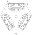
- a device for shaping an angle includes a substrate 1, a support platform 2 provided on the substrate 1, and an angled cutter head provided on the support platform 2.
- the angled cutter head is fixed movably up and down on the upper side of the support platform 2 via a spring connection device.
- the support platform 2 and three angled cutter heads with which the support platform cooperates are provided, and fixed in a Chinese character "pin" shape on the substrate 1.
- the rear side of the support platform 2 is provided with a limit device 5.
- the angled cutter head is provided thereon with three different angled cutter heads to facilitate bending the guide wire into a required angle.
- the side of the support platform 2 is provided with a guide wire entry platform 4.
- a plurality of guide wire entry holes 37 are provided on the guide wire entry platform 4. If the guide wire enters from different guide wire entry hole 37, the guide wire corresponds to different angles of the cutter head.
- the substrate 1 is provided thereon with the support platform 2.
- the front side of the support platform 2 is provided with the wire guide entry platform 4.
- the left and right sides of the support platform 2 are provided with a fixing post 6.
- the fixing post is provided with a first spring.
- An external housing 3 of the angled cutter head is installed on the fixing post.
- the central part of the external housing 3 of the angled cutter head is provided with a pressing plate 7.
- the lower side of the pressing plate 7 is provided with two second springs 8 symmetrically along a central axis thereof.
- the two second springs 8 are connected to the two ends of the angled cutter head 31.
- the angled cutter head 31 includes a first stepped platform 10 and a second stepped platform 11.
- the vertical side of the second stepped platform 11 adjacent to the support platform 2 is provided as a certain angle of a slope surface .
- the bottom surface of the first stepped platform 10 fits the upper side of the support platform 2 to fix the guide wire.
- the upper cutter head part on the second stepped platform 11 is pressed down to complete the task of bending the guide wire.
- a limit device 5 is provided at the rear side of the support platform 2. the positions of the limit device 5 and the support platform 2 can be adjusted according to the actual required length of the bent part of the guide wire.
- the technical solution provided by the present invention has the following advantages: 1.
- the present invention can accurately, stably and quickly bend the guide wire. 2.
- the bending needs of different angles of the wire guides can be met, that is, the wire guide head can be bent into different angles.
- the length of a bending part is different.
- the device can be used a plurality of times for the same patient in the same procedure. The device can be discarded after use, with low costs of use and high safety performance. 4.
- a set impact travel is precise.
- a sinking space of the angled cutter head is strictly limited.
- a moving space of the guide wire is strictly limited.
- a reaching space of the guide wire is limited, so that a bending guide wire with high precision can be prepared.
Landscapes
- Health & Medical Sciences (AREA)
- Life Sciences & Earth Sciences (AREA)
- Engineering & Computer Science (AREA)
- Heart & Thoracic Surgery (AREA)
- Biophysics (AREA)
- Pulmonology (AREA)
- Anesthesiology (AREA)
- Biomedical Technology (AREA)
- Hematology (AREA)
- Animal Behavior & Ethology (AREA)
- General Health & Medical Sciences (AREA)
- Public Health (AREA)
- Veterinary Medicine (AREA)
- Mechanical Engineering (AREA)
- Wire Processing (AREA)
- Media Introduction/Drainage Providing Device (AREA)
Applications Claiming Priority (2)
| Application Number | Priority Date | Filing Date | Title |
|---|---|---|---|
| CN202011448162.3A CN112719130B (zh) | 2020-12-11 | 2020-12-11 | 一种角度塑形装置 |
| PCT/CN2022/074449 WO2022122053A1 (fr) | 2020-12-11 | 2022-01-27 | Dispositif de mise en forme d'angle |
Publications (2)
| Publication Number | Publication Date |
|---|---|
| EP4260962A1 true EP4260962A1 (fr) | 2023-10-18 |
| EP4260962A4 EP4260962A4 (fr) | 2024-11-20 |
Family
ID=75599587
Family Applications (1)
| Application Number | Title | Priority Date | Filing Date |
|---|---|---|---|
| EP22729010.3A Pending EP4260962A4 (fr) | 2020-12-11 | 2022-01-27 | Dispositif de mise en forme d'angle |
Country Status (5)
| Country | Link |
|---|---|
| US (1) | US20240050710A1 (fr) |
| EP (1) | EP4260962A4 (fr) |
| JP (1) | JP7408023B2 (fr) |
| CN (1) | CN112719130B (fr) |
| WO (1) | WO2022122053A1 (fr) |
Families Citing this family (3)
| Publication number | Priority date | Publication date | Assignee | Title |
|---|---|---|---|---|
| CN112719130B (zh) * | 2020-12-11 | 2022-02-22 | 张健 | 一种角度塑形装置 |
| CN114768097B (zh) * | 2022-03-31 | 2025-10-21 | 中国人民解放军联勤保障部队第九〇〇医院 | 一种心脏起搏器的电极导丝塑形装置 |
| CN118557873B (zh) * | 2024-06-07 | 2026-04-03 | 中国人民解放军陆军军医大学第一附属医院 | 微导管塑形装置 |
Family Cites Families (18)
| Publication number | Priority date | Publication date | Assignee | Title |
|---|---|---|---|---|
| JPH0375545U (fr) * | 1989-11-27 | 1991-07-29 | ||
| JP3345822B2 (ja) * | 1995-01-27 | 2002-11-18 | 沖電気工業株式会社 | 半導体装置のリード加工方法及びその加工用金型 |
| JP3226035B2 (ja) * | 1999-01-26 | 2001-11-05 | サンケン電気株式会社 | 電子部品の位置決めリード曲げ装置及び曲げ法 |
| US10363389B2 (en) * | 2009-04-03 | 2019-07-30 | Scientia Vascular, Llc | Micro-fabricated guidewire devices having varying diameters |
| JP5620770B2 (ja) * | 2010-09-24 | 2014-11-05 | テルモ株式会社 | ガイドワイヤ形状付け用補助具 |
| JP5863112B2 (ja) * | 2012-08-21 | 2016-02-16 | 朝日インテック株式会社 | シェイピングデバイス |
| JP5995194B2 (ja) * | 2012-10-01 | 2016-09-21 | ニプロ株式会社 | ガイドワイヤ用シェイピング器具 |
| CN204953745U (zh) * | 2015-08-17 | 2016-01-13 | 歌尔声学股份有限公司 | 针头弯折装置 |
| CN205253974U (zh) * | 2015-12-25 | 2016-05-25 | 北京迪赛奇正科技有限公司 | 电子元件引脚成型装置 |
| CN106334732B (zh) * | 2016-11-04 | 2018-12-18 | 芜湖市恒浩机械制造有限公司 | 一种汽车板材部件折弯机 |
| CN106799443A (zh) * | 2017-03-21 | 2017-06-06 | 天津芮盛汽车部件有限公司 | 钢丝折弯导线套 |
| CN106994491B (zh) * | 2017-04-27 | 2018-08-28 | 邓小华 | 冠脉导丝尖端精确定型装置 |
| CN206912120U (zh) * | 2017-06-15 | 2018-01-23 | 南通同洲电子有限责任公司 | 一种成型装置 |
| CN207839918U (zh) * | 2018-01-20 | 2018-09-11 | 青岛新鲁同钢构有限公司 | 一种多角度钢筋折弯模具 |
| CN108500176A (zh) * | 2018-03-27 | 2018-09-07 | 斯沃博达汽车电子(昆山)有限公司 | 车用感应器压合折弯结构 |
| CN208214151U (zh) * | 2018-04-28 | 2018-12-11 | 刘畅 | 用于钢筋弯折的装置 |
| JP2022055080A (ja) * | 2020-09-28 | 2022-04-07 | 学校法人 聖マリアンナ医科大学 | ガイドワイヤ付形具及びガイドワイヤ付形方法 |
| CN112719130B (zh) * | 2020-12-11 | 2022-02-22 | 张健 | 一种角度塑形装置 |
-
2020
- 2020-12-11 CN CN202011448162.3A patent/CN112719130B/zh active Active
-
2022
- 2022-01-27 EP EP22729010.3A patent/EP4260962A4/fr active Pending
- 2022-01-27 WO PCT/CN2022/074449 patent/WO2022122053A1/fr not_active Ceased
- 2022-01-27 JP JP2023544622A patent/JP7408023B2/ja active Active
- 2022-01-27 US US18/266,556 patent/US20240050710A1/en active Pending
Also Published As
| Publication number | Publication date |
|---|---|
| EP4260962A4 (fr) | 2024-11-20 |
| CN112719130B (zh) | 2022-02-22 |
| CN112719130A (zh) | 2021-04-30 |
| WO2022122053A1 (fr) | 2022-06-16 |
| JP2023551067A (ja) | 2023-12-06 |
| US20240050710A1 (en) | 2024-02-15 |
| JP7408023B2 (ja) | 2024-01-04 |
Similar Documents
| Publication | Publication Date | Title |
|---|---|---|
| EP4260962A1 (fr) | Dispositif de mise en forme d'angle | |
| CA1263580A (fr) | Methode et appareil pour guider un catheter dans les ventricules du cerveau humain | |
| CA1068512A (fr) | Dispositif et methode visant a pratiquer des ponctions normales et reproductibles | |
| CN213821701U (zh) | 一种介入手术机器人导丝夹紧力控制装置 | |
| US20160284238A1 (en) | Simulated organ | |
| CN111467611B (zh) | 分体式多针管注射装置 | |
| CN116407186B (zh) | 穿刺锁定装置及缝合设备 | |
| CN216703151U (zh) | 一种导丝塑形器 | |
| US20030198574A1 (en) | Apparatus for handling biopsy specimens, and method for using it | |
| CN216603020U (zh) | 一种可移动穿刺架及超声穿刺设备 | |
| CN108852452B (zh) | 医用动脉血管夹钳 | |
| CN210606950U (zh) | 变压器铁芯自动叠装生产线中柱硅钢片步进定位装置 | |
| WO2024152863A1 (fr) | Seringue d'injection quantitative | |
| US11951271B2 (en) | Method of manufacturing an in-plane metal microneedle array | |
| CN212235513U (zh) | 分体式多针管注射装置 | |
| CN222657575U (zh) | 医用穿通装置 | |
| CN223106855U (zh) | 一种蒸汽消融导管穿刺针出针长度及角度测试装置 | |
| CN224189193U (zh) | 齿轮内径及齿棒距的测量装置 | |
| CN219516466U (zh) | 一种机器人末端引导穿刺夹持装置及机器人 | |
| CN215038152U (zh) | 一种便携式导管打孔装置 | |
| CN222644673U (zh) | 一种便于调节的简易裁切机构 | |
| CN222398669U (zh) | 一种肺穿刺定位调节器 | |
| CN222536627U (zh) | 弹簧熔头治具和激光加工设备 | |
| CN216860309U (zh) | 新能源汽配模具多功能支撑柱组件 | |
| CN114102972B (zh) | 一种硅胶导管尖端成型方法 |
Legal Events
| Date | Code | Title | Description |
|---|---|---|---|
| STAA | Information on the status of an ep patent application or granted ep patent |
Free format text: STATUS: THE INTERNATIONAL PUBLICATION HAS BEEN MADE |
|
| PUAI | Public reference made under article 153(3) epc to a published international application that has entered the european phase |
Free format text: ORIGINAL CODE: 0009012 |
|
| STAA | Information on the status of an ep patent application or granted ep patent |
Free format text: STATUS: REQUEST FOR EXAMINATION WAS MADE |
|
| 17P | Request for examination filed |
Effective date: 20230609 |
|
| AK | Designated contracting states |
Kind code of ref document: A1 Designated state(s): AL AT BE BG CH CY CZ DE DK EE ES FI FR GB GR HR HU IE IS IT LI LT LU LV MC MK MT NL NO PL PT RO RS SE SI SK SM TR |
|
| XX | Miscellaneous (additional remarks) |
Free format text: THE FILING DATE OF THE INTERNATIONAL APPLICATION IS WITHIN TWO MONTHS FROM THE DATE OF EXPIRATION OF THE PRIORITY PERIOD (R. 26BIS.3 PCT). |
|
| DAV | Request for validation of the european patent (deleted) | ||
| DAX | Request for extension of the european patent (deleted) | ||
| A4 | Supplementary search report drawn up and despatched |
Effective date: 20241022 |
|
| RIC1 | Information provided on ipc code assigned before grant |
Ipc: A61M 25/01 20060101ALI20241016BHEP Ipc: A61M 25/09 20060101ALI20241016BHEP Ipc: B21F 1/00 20060101AFI20241016BHEP |