EP4260977B1 - Outil de coupe - Google Patents
Outil de coupe Download PDFInfo
- Publication number
- EP4260977B1 EP4260977B1 EP21903182.0A EP21903182A EP4260977B1 EP 4260977 B1 EP4260977 B1 EP 4260977B1 EP 21903182 A EP21903182 A EP 21903182A EP 4260977 B1 EP4260977 B1 EP 4260977B1
- Authority
- EP
- European Patent Office
- Prior art keywords
- sensors
- substrate
- cutting tool
- outer peripheral
- recess
- Prior art date
- Legal status (The legal status is an assumption and is not a legal conclusion. Google has not performed a legal analysis and makes no representation as to the accuracy of the status listed.)
- Active
Links
Images


Classifications
-
- B—PERFORMING OPERATIONS; TRANSPORTING
- B23—MACHINE TOOLS; METAL-WORKING NOT OTHERWISE PROVIDED FOR
- B23B—TURNING; BORING
- B23B29/00—Holders for non-rotary cutting tools; Boring bars or boring heads; Accessories for tool holders
- B23B29/04—Tool holders for a single cutting tool
- B23B29/12—Special arrangements on tool holders
-
- B—PERFORMING OPERATIONS; TRANSPORTING
- B23—MACHINE TOOLS; METAL-WORKING NOT OTHERWISE PROVIDED FOR
- B23B—TURNING; BORING
- B23B31/00—Chucks; Expansion mandrels; Adaptations thereof for remote control
- B23B31/005—Cylindrical shanks of tools
-
- B—PERFORMING OPERATIONS; TRANSPORTING
- B23—MACHINE TOOLS; METAL-WORKING NOT OTHERWISE PROVIDED FOR
- B23C—MILLING
- B23C5/00—Milling-cutters
- B23C5/02—Milling-cutters characterised by the shape of the cutter
- B23C5/10—Shank-type cutters, i.e. with an integral shaft
- B23C5/109—Shank-type cutters, i.e. with an integral shaft with removable cutting inserts
-
- B—PERFORMING OPERATIONS; TRANSPORTING
- B23—MACHINE TOOLS; METAL-WORKING NOT OTHERWISE PROVIDED FOR
- B23C—MILLING
- B23C9/00—Details or accessories so far as specially adapted to milling machines or cutter
-
- B—PERFORMING OPERATIONS; TRANSPORTING
- B23—MACHINE TOOLS; METAL-WORKING NOT OTHERWISE PROVIDED FOR
- B23Q—DETAILS, COMPONENTS, OR ACCESSORIES FOR MACHINE TOOLS, e.g. ARRANGEMENTS FOR COPYING OR CONTROLLING; MACHINE TOOLS IN GENERAL CHARACTERISED BY THE CONSTRUCTION OF PARTICULAR DETAILS OR COMPONENTS; COMBINATIONS OR ASSOCIATIONS OF METAL-WORKING MACHINES, NOT DIRECTED TO A PARTICULAR RESULT
- B23Q17/00—Arrangements for observing, indicating or measuring on machine tools
- B23Q17/09—Arrangements for observing, indicating or measuring on machine tools for indicating or measuring cutting pressure or for determining cutting-tool condition, e.g. cutting ability, load on tool
- B23Q17/0995—Tool life management
-
- B—PERFORMING OPERATIONS; TRANSPORTING
- B23—MACHINE TOOLS; METAL-WORKING NOT OTHERWISE PROVIDED FOR
- B23B—TURNING; BORING
- B23B2231/00—Details of chucks, toolholder shanks or tool shanks
- B23B2231/02—Features of shanks of tools not relating to the operation performed by the tool
- B23B2231/0216—Overall cross sectional shape of the shank
- B23B2231/0228—Square
-
- B—PERFORMING OPERATIONS; TRANSPORTING
- B23—MACHINE TOOLS; METAL-WORKING NOT OTHERWISE PROVIDED FOR
- B23B—TURNING; BORING
- B23B2231/00—Details of chucks, toolholder shanks or tool shanks
- B23B2231/02—Features of shanks of tools not relating to the operation performed by the tool
- B23B2231/0216—Overall cross sectional shape of the shank
- B23B2231/0244—Special forms not otherwise provided for
-
- B—PERFORMING OPERATIONS; TRANSPORTING
- B23—MACHINE TOOLS; METAL-WORKING NOT OTHERWISE PROVIDED FOR
- B23B—TURNING; BORING
- B23B2260/00—Details of constructional elements
- B23B2260/128—Sensors
-
- B—PERFORMING OPERATIONS; TRANSPORTING
- B23—MACHINE TOOLS; METAL-WORKING NOT OTHERWISE PROVIDED FOR
- B23B—TURNING; BORING
- B23B2265/00—Details of general geometric configurations
- B23B2265/32—Polygonal
-
- B—PERFORMING OPERATIONS; TRANSPORTING
- B23—MACHINE TOOLS; METAL-WORKING NOT OTHERWISE PROVIDED FOR
- B23B—TURNING; BORING
- B23B2270/00—Details of turning, boring or drilling machines, processes or tools not otherwise provided for
- B23B2270/48—Measuring or detecting
-
- B—PERFORMING OPERATIONS; TRANSPORTING
- B23—MACHINE TOOLS; METAL-WORKING NOT OTHERWISE PROVIDED FOR
- B23C—MILLING
- B23C2260/00—Details of constructional elements
- B23C2260/76—Sensors
-
- B—PERFORMING OPERATIONS; TRANSPORTING
- B23—MACHINE TOOLS; METAL-WORKING NOT OTHERWISE PROVIDED FOR
- B23C—MILLING
- B23C2265/00—Details of general geometric configurations
- B23C2265/32—Polygonal
-
- B—PERFORMING OPERATIONS; TRANSPORTING
- B23—MACHINE TOOLS; METAL-WORKING NOT OTHERWISE PROVIDED FOR
- B23Q—DETAILS, COMPONENTS, OR ACCESSORIES FOR MACHINE TOOLS, e.g. ARRANGEMENTS FOR COPYING OR CONTROLLING; MACHINE TOOLS IN GENERAL CHARACTERISED BY THE CONSTRUCTION OF PARTICULAR DETAILS OR COMPONENTS; COMBINATIONS OR ASSOCIATIONS OF METAL-WORKING MACHINES, NOT DIRECTED TO A PARTICULAR RESULT
- B23Q17/00—Arrangements for observing, indicating or measuring on machine tools
- B23Q17/09—Arrangements for observing, indicating or measuring on machine tools for indicating or measuring cutting pressure or for determining cutting-tool condition, e.g. cutting ability, load on tool
- B23Q17/0904—Arrangements for observing, indicating or measuring on machine tools for indicating or measuring cutting pressure or for determining cutting-tool condition, e.g. cutting ability, load on tool before or after machining
- B23Q17/0909—Detection of broken tools
-
- B—PERFORMING OPERATIONS; TRANSPORTING
- B23—MACHINE TOOLS; METAL-WORKING NOT OTHERWISE PROVIDED FOR
- B23Q—DETAILS, COMPONENTS, OR ACCESSORIES FOR MACHINE TOOLS, e.g. ARRANGEMENTS FOR COPYING OR CONTROLLING; MACHINE TOOLS IN GENERAL CHARACTERISED BY THE CONSTRUCTION OF PARTICULAR DETAILS OR COMPONENTS; COMBINATIONS OR ASSOCIATIONS OF METAL-WORKING MACHINES, NOT DIRECTED TO A PARTICULAR RESULT
- B23Q17/00—Arrangements for observing, indicating or measuring on machine tools
- B23Q17/09—Arrangements for observing, indicating or measuring on machine tools for indicating or measuring cutting pressure or for determining cutting-tool condition, e.g. cutting ability, load on tool
- B23Q17/0952—Arrangements for observing, indicating or measuring on machine tools for indicating or measuring cutting pressure or for determining cutting-tool condition, e.g. cutting ability, load on tool during machining
- B23Q17/0957—Detection of tool breakage
-
- B—PERFORMING OPERATIONS; TRANSPORTING
- B23—MACHINE TOOLS; METAL-WORKING NOT OTHERWISE PROVIDED FOR
- B23Q—DETAILS, COMPONENTS, OR ACCESSORIES FOR MACHINE TOOLS, e.g. ARRANGEMENTS FOR COPYING OR CONTROLLING; MACHINE TOOLS IN GENERAL CHARACTERISED BY THE CONSTRUCTION OF PARTICULAR DETAILS OR COMPONENTS; COMBINATIONS OR ASSOCIATIONS OF METAL-WORKING MACHINES, NOT DIRECTED TO A PARTICULAR RESULT
- B23Q17/00—Arrangements for observing, indicating or measuring on machine tools
- B23Q17/09—Arrangements for observing, indicating or measuring on machine tools for indicating or measuring cutting pressure or for determining cutting-tool condition, e.g. cutting ability, load on tool
- B23Q17/0952—Arrangements for observing, indicating or measuring on machine tools for indicating or measuring cutting pressure or for determining cutting-tool condition, e.g. cutting ability, load on tool during machining
- B23Q17/0966—Arrangements for observing, indicating or measuring on machine tools for indicating or measuring cutting pressure or for determining cutting-tool condition, e.g. cutting ability, load on tool during machining by measuring a force on parts of the machine other than a motor
-
- B—PERFORMING OPERATIONS; TRANSPORTING
- B23—MACHINE TOOLS; METAL-WORKING NOT OTHERWISE PROVIDED FOR
- B23Q—DETAILS, COMPONENTS, OR ACCESSORIES FOR MACHINE TOOLS, e.g. ARRANGEMENTS FOR COPYING OR CONTROLLING; MACHINE TOOLS IN GENERAL CHARACTERISED BY THE CONSTRUCTION OF PARTICULAR DETAILS OR COMPONENTS; COMBINATIONS OR ASSOCIATIONS OF METAL-WORKING MACHINES, NOT DIRECTED TO A PARTICULAR RESULT
- B23Q17/00—Arrangements for observing, indicating or measuring on machine tools
- B23Q17/09—Arrangements for observing, indicating or measuring on machine tools for indicating or measuring cutting pressure or for determining cutting-tool condition, e.g. cutting ability, load on tool
- B23Q17/0952—Arrangements for observing, indicating or measuring on machine tools for indicating or measuring cutting pressure or for determining cutting-tool condition, e.g. cutting ability, load on tool during machining
- B23Q17/0985—Arrangements for observing, indicating or measuring on machine tools for indicating or measuring cutting pressure or for determining cutting-tool condition, e.g. cutting ability, load on tool during machining by measuring temperature
Definitions
- the present disclosure relates to a cutting tool.
- WO2019121189A1 relates to a force measurement module, tool-holder and robot arm end equipped with such a force measurement module, which forms the basis of the preamble of appended claim 1.
- a cutting tool includes a shaft extending along a rotation axis and having a first end portion and a second end portion, and a sensor device disposed in such a manner as to surround a portion of the shaft in a longitudinal direction of the shaft.
- the cutting tool is configured to cut a workpiece by rotating around the rotation axis of the shaft.
- the sensor device includes a sensor module including a plurality of first sensors configured to detect a first physical quantity of the shaft, a substrate electrically connected to the first sensors, and a wireless communication unit electrically connected to the substrate and configured to transmit a signal including information of the first physical quantity detected by the first sensors to outside and a housing accommodating the sensor module.
- a region of the shaft surrounded by the sensor device includes a first region having a shape of a 4n-sided polygon when viewed from a direction in which the rotation axis extends.
- the n is a natural number of two or more.
- the plurality of first sensors are arranged on at least two of outer peripheral surfaces of the first region, each of the outer peripheral surfaces of the first region corresponding to one of sides of the 4n-sided polygon, perpendicular lines of the at least two outer peripheral surfaces passing through the rotation axis and intersecting each other at 90 degrees.
- more useful data can be obtained by the sensor.
- a cutting tool of the present disclosure includes a shaft extending along a rotation axis and having a first end portion and a second end portion, and a sensor device disposed in such a manner as to surround a portion of the shaft in a longitudinal direction of the shaft.
- the cutting tool is configured to cut a workpiece by rotating around the rotation axis of the shaft.
- the sensor device includes a sensor module including a plurality of first sensors configured to detect a first physical quantity of the shaft, a substrate electrically connected to the first sensors, and a wireless communication unit electrically connected to the substrate and configured to transmit a signal including information of the first physical quantity detected by the first sensors to outside and a housing accommodating the sensor module.
- a region of the shaft surrounded by the sensor device includes a first region having a shape of a 4n-sided polygon when viewed from a direction in which the rotation axis extends.
- the n is a natural number of two or more.
- the plurality of first sensors are arranged on at least two of outer peripheral surfaces of the first region, each of the outer peripheral surfaces of the first region corresponding to one of sides of the 4n-sided polygon, perpendicular lines of the at least two outer peripheral surfaces passing through the rotation axis and intersecting each other at 90 degrees.
- a region of the shaft surrounded by the sensor device includes a first region having a shape of a 4n-sided polygon (n is a natural number of two or more) when viewed from a direction in which the rotation axis extends.
- a plurality of first sensors configured to detect the same physical quantity (first physical quantity) are arranged on at least two of outer peripheral surface of the first region each corresponding to one of sides of the 4n-sided polygon, perpendicular lines of the at least two outer peripheral surfaces passing through the rotation axis and intersecting each other at 90 degrees. In this way, sensors detecting the same physical quantity are arranged with a phase difference of 90 degrees in rotation about the rotation axis.
- the first physical quantity in the plane perpendicular to the rotation axis may be appropriately ascertained.
- the physical quantity ascertained in this way is useful for ascertaining the state of the cutting tool during machining.
- more useful data can be obtained by the sensor.
- angles formed by perpendicular lines of pairs of the outer peripheral surfaces of the first region, the perpendicular lines passing through the rotation axis, and each of the pairs corresponding to respective of the sides of the 4n-sided polygon that are adjacent to each other in a circumferential direction, are equal to each other. In this way, it becomes easy to ensure the symmetry of the outer peripheral surface of the first region where the sensor can be arranged with respect to the rotation axis.
- the substrate may be disposed in such a manner as to extend along the outer peripheral surfaces of the first region corresponding to a plurality of sides of a 4n-sided polygon when viewed from the direction in which the rotation axis extends. In this way, it is easy to prevent the substrate module from moving relative to the shaft. As a result, the accuracy of the physical quantity obtained from the first sensor is increased.
- a first recess may be formed in an outer peripheral surface of the shaft.
- Each of the first sensors may be accommodated in the first recess. In this way, this facilitates the arrangement of the first sensor.
- the first sensors may be strain sensors.
- the sensor arrangement of the present disclosure is suitable for measuring strain.
- a second recess may be formed in an outer peripheral surface of the shaft.
- Each of the first sensors may be arranged in such a manner as to straddle the second recess.
- the first sensor is a strain sensor, by arranging the first sensor so as to straddle the second recess as described above, strain can be easily measured with high accuracy.
- the first sensors may be strain sensors.
- An outer peripheral surface of the shaft may have a first recess and a second recess, the second recess being deeper than the first recess and overlapping the first recess.
- Each of the first sensors may be arranged in such a manner as to straddle the second recess and accommodated in the first recess. With this configuration, the first sensor can be easily arranged and the strain can be easily measured with high accuracy by the first sensor.
- the second recess may be a groove extending in a circumferential direction of the shaft.
- the first recess may extend in direction perpendicular to the second recess.
- the first sensor may be acceleration sensors.
- the sensor arrangement of the present disclosure is suitable for measuring acceleration.
- the sensor module may further include a plurality of second sensors configured to detect a second physical quantity of the shaft different from the first physical quantity of the shaft.
- the substrate may be electrically connected to the second sensors.
- the wireless communication unit may be electrically connected to the substrate and configured to transmit a signal including information of the second physical quantity detected by the second sensors to outside.
- the second sensor that detects the second physical quantity different from the first physical quantity, two types of physical quantities can be ascertained at the same time. As a result, the sensor can obtain more useful data for ascertaining the state of the cutting tool during machining.
- the first sensors may be strain sensors configured to detect strain as the first physical quantity.
- the second sensors may be acceleration sensors configured to detect acceleration as the second physical quantity. In this way, the strain and acceleration of the cutting tool can be ascertained simultaneously.
- the first sensors and the second sensors may be arranged on the outer peripheral surfaces of the first region, and the outer peripheral surfaces on which the first sensors are arranged correspond to the sides of the 4n-sided polygon different from the sides of the 4n-sided polygon that the outer peripheral surfaces on which the second sensors are arranged. In this way, this facilitates the arrangement of the sensor.
- the sensor module further may include a wiring line connected to the first sensor.
- the wiring line may be configured to connect the first sensors to the substrate with slack in the wiring line.
- the first sensor can be easily arranged without adjusting the length of the wiring line by allowing the wiring line of the first sensor to have slack.
- the sensor module may further include an AD converter disposed on the substrate.
- a thickness of the substrate is smaller than a thickness of the substrate in the second region and smaller than a thickness of the substrate in the third region, the substrate being bent in the fourth region.
- the substrate may be a rigid substrate.
- a groove may be formed in the fourth region of the substrate, the groove connecting both ends of the substrate in the direction in which the rotation axis extends.
- the substrate may include a main body being a flexible substrate and reinforcing plates disposed in the second region and the third region, each of the reinforcing plates having a Young's modulus higher than a Young's modulus of the main body.
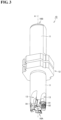
- FIG. 1 is a schematic perspective view showing the structure of a cutting tool.
- a cutting tool 1 according to the present embodiment includes a shaft 10 and a sensor device 20.
- Shaft 10 extends along a rotation axis A from a first end portion 10A to a second end portion 10B.
- Sensor device 20 is arranged to surround a portion of the longitudinal direction of shaft 10.
- shaft 10 a plurality of recesses 13 (four recesses 13 in this case) which are open in first end portion 10A and the outer peripheral surface are formed at equal intervals in the circumferential direction.
- a cutting insert 91 is attached to the wall defining recess 13.
- a workpiece (not shown) may be machined by rotating cutting tool 1 around rotation axis A to bring cutting insert 91 into contact with the workpiece. That is, cutting tool 1 is a cutting tool that cuts a workpiece by rotating around rotation axis A of shaft 10.
- FIG. 2 is a schematic perspective view showing the structure of the shaft viewed from second end portion 10B.
- FIG. 3 is a schematic perspective view showing the structure of the shaft viewed from first end portion 10A.
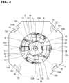
- FIG. 4 is a schematic plan view showing the structure of the shaft viewed from the first end portion in the rotation axis direction.
- FIG. 5 is a schematic plan view showing the structure of the shaft viewed from the second end portion in the rotation axis direction.
- FIG. 6 is a schematic plan view showing the structure of the shaft viewed in a direction perpendicular to the axial direction.
- FIG. 7 is a schematic cross-sectional view showing a cross section taken along line VII-VII of FIG. 5 .
- the structure of shaft 10 will be described with reference to FIGS. 2 to 7 .
- shaft 10 includes a main body 11 and an increased-diameter portion 12 as a first region.
- Main body 11 has a cylindrical shape.
- Rotation axis A coincides with the central axis of main body 11.
- Increased-diameter portion 12 is a portion having a larger diameter than main body 11.
- increased-diameter portion 12 is disposed at the central portion in the longitudinal direction of main body 11.
- Increased-diameter portion 12 is disposed in a region of shaft 10 which is surrounded by sensor device 20.
- cutting insert 91 is attached to the wall surface defining recess 13 of shaft 10. Cutting insert 91 is fixed to shaft 10 by inserting and tightening a screw 92 into a screw hole formed in cutting insert 91.
- increased-diameter portion 12 has a shape of an octagonal prism.
- increased-diameter portion 12 has an octagonal shape when viewed from a direction in which the rotation axis A extends. More specifically, increased-diameter portion 12 has, in a cross-section perpendicular to rotation axis A, the shape of an octagon obtained by removing four isosceles right triangles with the same shape from each of the four corners of a square. Rotation axis A passes through the center of gravity of the octagon. This octagonal shape is the same in the direction in which rotation axis A extends.
- a central axis of main body 11 and a central axis of increased-diameter portion 12 coincide with each other.
- the central axis of increased-diameter portion 12 means a straight line passing through the center of gravity of the octagon.
- the octagon when viewed in the direction in which the rotation axis A extends, is formed by an outer peripheral surface 12A corresponding to a long side and an outer peripheral surface 12B corresponding to a short side shorter than the long side.
- the long sides and the short side are alternately arranged.
- Angles ⁇ formed by perpendicular lines L A and L B of pairs of outer peripheral surfaces 12A and 12B of increased-diameter portion 12 are equal to each other, perpendicular lines L A and L B passing through rotation axis A, and each of the pairs corresponding to two of the sides of the octagon that are adjacent to each other in the circumferential direction.
- angle ⁇ is 45 degrees.
- the shape of the octagon is not limited to the shape described above, and the lengths of outer peripheral surface 12A and outer peripheral surface 12B may be the same when viewed in the direction in which the rotation axis A extends.
- a first recess 16 extending in the direction in which rotation axis A extends, is formed in each outer peripheral surface 12B.
- a bottom surface 16A defining first recess 16 is planar.
- First recess 16 is disposed at a position crossing perpendicular line L B .
- First recess 16 extends through outer peripheral surface 12B in the direction in which rotation axis A extends.
- a second recess 15, extending in the circumferential direction of increased-diameter portion 12, is formed in outer peripheral surfaces 12A, 12B of increased-diameter portion 12.
- Second recess 15 is formed so as to overlap first recess 16.
- Second recess 15 intersects (is orthogonal to) first recess 16.
- Second recess 15 is formed over the entire circumference of outer peripheral surfaces 12A, 12B of increased-diameter portion 12. That is, second recess 15 is formed in an annular shape.
- a depth d 2 of second recess 15 is greater than a depth d 1 of first recess 16.
- a first small-diameter portion 11A having a smaller diameter than other portions is formed at a boundary portion near first end portion 10A between main body 11 and increased-diameter portion 12.
- a second small-diameter portion 11B having a smaller diameter than other portions is formed at a boundary portion near second end portion 10B between main body 11 and increased-diameter portion 12.
- a through hole 10C penetrating through shaft 10 in the direction in which rotation axis A extends is formed in shaft 10. Through hole 10C extends to include rotation axis A.
- sensor device 20 includes a sensor module 80 and a housing 21 for accommodating sensor module 80.
- Sensor module 80 includes a plurality of strain sensors 31 as a plurality of first sensors, a substrate 49 electrically connected to strain sensors 31, and a wireless communication unit 51 (see FIGS. 10 and 11 ) electrically connected to substrate 49.
- Strain sensor 31 detects strain as a first physical quantity of shaft 10.
- Wireless communication unit 51 transmits a signal including information on the strain detected by strain sensor 31 to the outside.
- strain sensor 31 constitutes a strain sensor component 30.
- Strain sensor component 30 includes strain sensor 31 and a wiring line 32 which is connected to strain sensor 31 and has a connector 33 at its tip.
- Wiring line 32 has a belt-like shape.
- Strain sensor 31 is arranged near one end of wiring line 32.
- Connector 33 is disposed at the other end of wiring line 32.
- substrate 49 constitutes a substrate module 40.
- Substrate 49 includes a substrate main body made of an insulator such as resin and a circuit pattern (not shown) made of a conductor such as copper formed on the surface of the substrate main body.
- Substrate module 40 includes substrate 49, wireless communication unit 51, acceleration sensors 52 as second sensors, sockets 53, and an AD converter 54.
- Wireless communication unit 51, acceleration sensors 52, sockets 53, and AD converter 54 are disposed on one main surface of substrate 49 and are electrically connected to substrate 49 (the circuit pattern of substrate 49).
- Acceleration sensors 52 detects an acceleration as a second physical quantity of shaft 10.
- a plurality of acceleration sensors 52 are arranged on substrate 49.
- Wireless communication unit 51 is electrically connected to acceleration sensor 52 via substrate 49.
- Wireless communication unit 51 transmits a signal including information on the acceleration of shaft 10 detected by acceleration sensors 52 to the outside.
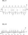
- Substrate 49 is a rigid substrate. Substrate 49 has a belt-like shape. Substrate 49 includes a first area 41, a second area 42, a third area 43, a fourth area 44, a fifth area 45, a sixth area 46, a seventh area 47, and an eighth area 48. First area 41 to eighth area 48 are arranged in this order in the longitudinal direction of substrate 49.
- Wireless communication unit 51 and acceleration sensor 52 are mounted on first area 41.
- Sockets 53 are mounted on second area 42.
- Acceleration sensor 52 are mounted on third area 43.
- Socket 53 is mounted in fourth area 44.
- Acceleration sensor 52 and AD converter 54 are mounted in fifth area 45. Socket 53 is mounted on sixth area 46. Acceleration sensor 52 is mounted in seventh area 47. Socket 53 is mounted in eighth area 48.
- a bendable region 49A having a smaller thickness than other portions is formed between first area 41 to eighth area 48 adjacent to each other.
- Bendable region 49A is a groove connecting both ends of substrate 49 in a width direction (a direction perpendicular to a longitudinal direction).
- First area 41 is a second area in which wireless communication unit 51 is mounted.
- Fifth area 45 is a third area in which AD converter 54 is mounted.
- Bendable region 49A is a fourth region having a smaller thickness than the second region and the third region.
- the lengths of first area 41, third area 43, fifth area 45 and seventh area 47 in the longitudinal direction of substrate 49 correspond to the length of outer peripheral surface 12A which is the long side of the octagon when increased-diameter portion 12 is viewed from the direction in which rotation axis A extends.
- the lengths of second area 42, fourth area 44, sixth area 46 and eighth area 48 in the longitudinal direction of substrate 49 correspond to the length of outer peripheral surface 12B which is the short side of the octagon when increased-diameter portion 12 is viewed from the direction in which rotation axis A extends.
- Strain sensor component 30 is arranged such that strain sensor 31 spans second recess 15 and strain sensor 31 is accommodated in first recess 16 (see FIGS. 2 , 4 , 8 , etc.). Strain sensor component 30 is arranged on each of four outer peripheral surfaces 12B.
- strain sensor 31 is arranged on each of all outer peripheral surfaces 12B (outer peripheral surfaces corresponding to the short sides) of increased-diameter portion 12, each of outer peripheral surfaces of increased-diameter portion 12 corresponding to one side of the octagon, perpendicular lines L B passing through rotation axis A and intersecting each other at 90 degrees.
- substrate module 40 is wound around increased-diameter portion 12 such that the main surface of substrate 49 is in contact with outer peripheral surfaces 12A and 12B of increased-diameter portion 12, the main surface being opposite to the surface on which wireless communication unit 51, acceleration sensors 52, sockets 53, AD converter 54, and the like are mounted.
- first area 41, third area 43, fifth area 45, and seventh area 47 are arranged on outer peripheral surface 12A
- second area 42, fourth area 44, sixth area 46, and eighth area 48 are arranged on outer peripheral surface 12B.
- Substrate 49 is bent at bendable region 49A which is a groove connecting both ends in the direction in which rotation axis A extends (a groove connecting both ends in the width direction).
- substrate 49 when viewed from a direction in which rotation axis A extends, substrate 49 is disposed along outer peripheral surfaces 12A, 12B of increased-diameter portion 12. Sockets 53 are disposed on substrate 49 disposed on outer peripheral surface 12B. Connector 33 disposed at the end of wiring line 32 connected to strain sensor 31 is connected to socket 53. Thus, substrate 49 and strain sensor 31 are electrically connected to each other. As shown in FIG. 8 , wiring line 32 straddle substrate 49 in the width direction (direction in which rotation axis A extends). Wiring line 32 is warped in an arch shape. In other words, wiring line 32 connects strain sensor 31 and socket 53 with slack.
- Acceleration sensor 52 is arranged on first area 41, third area 43, fifth area 45, and seventh area 47 of substrate 49. Therefore, when substrate module 40 is installed in increased-diameter portion 12 as described above, acceleration sensor 52 is arranged on each of all outer peripheral surfaces 12A (outer peripheral surfaces corresponding to the long sides) of increased-diameter portion 12, each of outer peripheral surfaces of increased-diameter portion 12 corresponding to one side of the octagon, perpendicular lines L A passing through rotation axis A and intersecting each other at 90 degrees when viewed from the direction in which rotation axis A extends. That is, strain sensor 31 and acceleration sensor 52 are arranged on outer peripheral surfaces 12A and 12B of increased-diameter portion 12 corresponding to the respective sides of the octagon different from each other.
- acceleration sensors 52 are arranged at a central portion in a short side direction of substrate 49 having a rectangular planar shape.
- acceleration sensors 52 and strain sensor 31 are arranged at the same position. In this way, the axial length required for arrangement of the sensor can be reduced. As a result, sensor device 20 can be reduced in size.
- FIGS. 10 and 8 in the direction in which rotation axis A extends, acceleration sensors 52 and strain sensor 31 are arranged at the same position. In this way, the axial length required for arrangement of the sensor can be reduced. As a result, sensor device 20 can be reduced in size.
- the state in which "acceleration sensors 52 and strain sensor 31 are arranged at the same position in the direction in which rotation axis A extends” means that a measurement range a of acceleration sensor 52 (specifically, the range in which the electrical resistance wiring line for detecting acceleration is arranged) and a measurement range b of strain sensor 31 (specifically, the range in which the electrical resistance wiring line for detecting strain is arranged) at least partially overlap in the direction in which rotation axis A extends.
- the positional relationship between acceleration sensors 52 and strain sensor 31 in the direction in which rotation axis A extends may be changed in consideration of the ease of detection of acceleration and strain.
- strain sensor 31 may be arranged at a position farther from first end portion 10A (a position farther from cutting insert 91 ; around an upper part in FIG. 8 ) than acceleration sensor 52.
- the strain of shaft 10 caused by the cutting process increases further away from the cutting insert.
- the acceleration of shaft 10 caused by the cutting process is greater at a position closer to the cutting insert. Therefore, by employing such an arrangement, the sensitivity of detection of strain and acceleration by strain sensor 31 and acceleration sensor 52 is improved.
- strain sensor 31 may be arranged at a position closer to first end portion 10A than acceleration sensor 52 (a position closer to cutting insert 91 ; around a lower part in FIG. 8 ).
- strain of shaft 10 at the position where strain sensor 31 is arranged may be too large in the above arrangement.
- strain sensor 31 by disposing strain sensor 31 at a position closer to first end portion 10A than acceleration sensor 52, it is possible to set the magnitude of the strain at the position where strain sensor 31 is arranged within a range in which strain sensor 31 easily detects the strain.
- strain sensor 31 includes a temperature sensor. That is, in the present embodiment, a sensor in which strain sensor 31 and the temperature sensor are integrated is employed as strain sensor 31.
- the temperature sensor does not necessarily have to be integrated with strain sensor 31, and may be a separate body. In this case, referring to FIG. 8 , the temperature sensor is arranged at the same position as strain sensor 31 in the direction in which rotation axis A extends. More specifically, referring to FIGS.
- the temperature sensor is arranged at an arbitrary position in an annular region of outer peripheral surfaces 12A and 12B of increased-diameter portion 12 corresponding to measurement range b of strain sensor 31 in the direction in which rotation axis A extends (a band-like region of outer peripheral surfaces 12A and 12B of increased-diameter portion 12 whose width coincides with measurement range b).
- the temperature sensor is not essential in the cutting tool of the present disclosure, but may be employed to detect the temperature of the location where strain sensor 31 is arranged or the region corresponding to measurement range b of strain sensor 31 in outer peripheral surfaces 12A and 12B of increased-diameter portion 12.
- the thermal strain at the location where strain sensor 31 is arranged or the region corresponding to measurement range b of strain sensor 31 in outer peripheral surfaces 12A and 12B of increased-diameter portion 12 may be calculated.
- Thermal strain is the product of temperature change and coefficient of linear expansion.
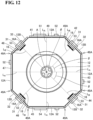
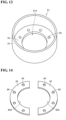
- housing 21 includes a housing main body 61, a first fixing member 63, a second fixing member 65, and a lid 22.
- housing main body 61 includes a disk-shaped bottom wall portion 24 having a through hole 61A at the center thereof, and a side wall portion 23 rising from the outer peripheral surface of bottom wall portion 24 and having a cylindrical shape.
- a plurality of screw holes 62 (here, eight crew holes 62) penetrating bottom wall portion 24 in the thickness direction are formed at equal intervals in the circumferential direction.
- Housing main body 61 is made of a metal, for example. Examples of the metal that can be employed include aluminum alloy and iron alloy (steel such as stainless steel).
- first fixing member 63 has a shape of an annular flat plate divided into two.
- First fixing member 63 is formed with a plurality of screw holes 64 (here, eight screw holes 64 in total in first fixing member 63 divided into two in this case) at equal intervals in the circumferential direction so as to correspond to screw holes 62 of bottom wall portion 24 of housing main body 61.
- An inner peripheral surface 63A of first fixing member 63 has a shape corresponding to first small-diameter portion 11A of shaft 10. When two first fixing members 63 are assembled into an annular shape, the diameter of inner peripheral surface 63A is equal to or slightly larger than the diameter of first small-diameter portion 11A.
- First fixing member 63 is made of a metal, for example. Examples of the metal that can be employed include an aluminum alloy and an iron alloy (steel such as stainless steel).
- second fixing member 65 is a part having a flat circular arc shape.
- housing 21 includes two second fixing members 65.
- An inner peripheral surface 65A of each second fixing member 65 has a shape corresponding to a part of the planar shape of the outer peripheral surface of increased-diameter portion 12, i.e. a shape corresponding to a part of an octagon.
- a plurality of screw holes 66 (here, two screw holes 66 for each second fixing member 65) so as to correspond to screw holes 62 of bottom wall portion 24 of housing main body 61 and screw holes 64 of first fixing member 63.
- the material constituting second fixing member 65 is resin, for example.
- lid (upper wall portion) 22 has a disk-like shape having a through hole 22A in the center thereof.
- Lid 22 is made of, for example, resin.
- Housing 21 may be installed in a state in which strain sensor component 30 and substrate module 40 are installed on shaft 10.
- housing main body 61 is disposed such that main body 11 of shaft 10 penetrating through hole 61A of bottom wall portion 24 of housing main body 61.
- first fixing member 63 is disposed on bottom wall portion 24
- first fixing member 63 is fitted into first small-diameter portion 11A such that inner peripheral surface 63A is in contact with the bottom wall of first small-diameter portion 11A of main body 11.
- second fixing member 65 is disposed on first fixing member 63 such that inner peripheral surface 65A is in contact with outer peripheral surfaces 12A and 12B of increased-diameter portion 12.
- housing main body 61, first fixing member 63 and second fixing member 65 are fixed to each other by a screw passing through screw hole 66 of second fixing member 65 and screw hole 64 of first fixing member 63 and reaching screw hole 62 of bottom wall portion 24.
- first fixing member 63 corresponds to the outer diameter of first small-diameter portion 11A
- the central axis of housing main body 61 coincides with rotation axis A.
- inner peripheral surface 65A of second fixing member 65 has a shape corresponding to a part of the planar shape of the outer peripheral surface of increased-diameter portion 12 (a shape corresponding to a part of an octagon), housing main body 61 is prevented from rotating in the circumferential direction relative to shaft 10.
- Lid (upper wall portion) 22 is fixed to increased-diameter portion 12 by a screw or the like, for example, in a state of being placed on an end surface of side wall portion 23 and an end surface of increased-diameter portion 12. In this way, housing 21 is fixed to shaft 10 in a state where sensor module 80 is accommodated therein.
- cutting tool 1 rotates about rotation axis A.
- strain and acceleration of shaft 10 are detected by strain sensor 31 and acceleration sensor 52, respectively.
- the strain and acceleration information which is an analog signal, is converted into a digital signal by AD converter 54, and then transmitted to the outside by wireless communication unit 51.
- lid (upper wall portion) 22 of housing 21 is made of resin, wireless communication unit 51 can transmit a signal to the outside through lid (upper wall portion) 22. This signal is externally received and analyzed to ascertain the state of shaft 10 in a plane perpendicular to the rotation axis.
- the region of shaft 10 surrounded by sensor device 20 includes increased-diameter portion 12 having an octagonal shape when viewed from the direction in which rotation axis A extends.
- a plurality of strain sensors 31 for detecting strain are arranged on outer peripheral surfaces 12B of increased-diameter portion 12, each of outer peripheral surfaces 12A and 12B of increased-diameter portion 12 corresponding to one side of the octagon, perpendicular lines L B passing through rotation axis A and intersecting each other at 90 degrees.
- the sensors for detecting strain are arranged with a phase difference of 90 degrees in the rotation around rotation axis A.
- cutting tool 1 of the present embodiment is a cutting tool capable of obtaining more useful data by the sensor.
- substrate 49 is disposed along outer peripheral surfaces 12A and 12B of increased-diameter portion 12 when viewed from the direction in which rotation axis A extends. This makes it difficult for substrate module 40 to move relative to shaft 10. As a result, the accuracy of information obtained from strain sensor 31 is increased.
- first recess 16 is formed in outer peripheral surface 12B of increased-diameter portion 12. Strain sensor 31 is accommodated in first recess 16. This facilitates the arrangement of strain sensor 31.
- second recess 15 is formed in outer peripheral surfaces 12A and 12B of increased-diameter portion 12.
- Strain sensor 31 is arranged in such a manner as to straddle second recess 15. This makes it easy to measure the strain with high accuracy.
- second recess 15 is deeper than first recess 16 and overlaps with first recess 16.
- sensor module 80 includes a plurality of acceleration sensors 52 for detecting the acceleration of the shaft.
- acceleration sensors 52 for detecting the acceleration of the shaft.
- strain sensor 31 and acceleration sensor 52 are arranged on outer peripheral surfaces 12A and 12B of increased-diameter portion 12 corresponding to the respective sides of the octagon different from each other. Although it is possible to arrange strain sensor 31 and acceleration sensor 52 on same outer peripheral surfaces 12A and 12B, it is easy to arrange the sensors by arranging them on different surfaces.
- wiring line 32 constituting strain sensor component 30 connects the strain sensor and socket 53 with slack. This makes it easy to arrangel strain sensor 31 without adjusting the length of wiring line 32.
- substrate 49 is bent in bendable region 49A having a smaller thickness than first area 41 on which wireless communication unit 51 is mounted and fifth area 45 on which AD converter 54 is mounted. Accordingly, substrate 49 can be easily deformed for installation while preventing wireless communication unit 51 and AD converter 54, which are relatively large components, from being peeled off or the like due to deformation of substrate 49.
- substrate 49 is a rigid substrate.
- a groove connecting both ends in the direction in which rotation axis A extends is formed in bendable region 49A of substrate 49.
- bendable region 49A can be easily formed.
- the two types of sensors i.e., strain sensor 31 and acceleration sensor 52
- strain sensor 31 and acceleration sensor 52 are employed as the first sensor and the second sensor, respectively.
- acceleration sensor 52 as the second sensor may be omitted.
- strain sensor 31 may be omitted and only acceleration sensor 52 may be employed.
- the first sensor may be an acceleration sensor.
- a sensor that detects a physical quantity other than strain and acceleration may be employed instead of one or both of strain sensor 31 and acceleration sensor 52, or may be employed in addition to them.
- the end mill has been described as an example of the cutting tool of the present disclosure, but the cutting tool of the present disclosure is not limited thereto.
- the cutting tool of the present disclosure may be, for example, a drill, a milling cutter, a boring, a reamer, a tap, etc.
- increased-diameter portion 12 of shaft 10 disposed in the region surrounded by sensor device 20 has an octagonal shape when viewed from the direction in which rotation axis A extends.
- the planar shape of the increased-diameter portion may be a 4n-sided polygon (n is a natural number of 2 or more), and may be, for example, a dodecagon, a hexadecagon, or an icosagon.
- strain sensor 31 is arranged on each of all of outer peripheral surfaces 12B (four surfaces) of increased-diameter portion 12, each of outer peripheral surfaces 12A and 12B of increased-diameter portion 12 corresponding to one side of the octagon, the perpendicular lines of outer peripheral surfaces 12B passing through rotation axis A and intersecting each other at 90 degrees. Strain sensor 31 may be arranged on at least two surfaces.
- a strain sensor is arranged on each of a set of a total of two outer peripheral surfaces, which are a first outer peripheral surface and a second outer peripheral surface of which perpendicular lines pass through the rotation axis and intersect each other at 90 degrees, or arranged on each of a set of outer peripheral surfaces, which are the two outer peripheral surfaces and a third outer peripheral surface, the perpendicular line of the third outer peripheral surface passing through the rotation axis and intersecting the perpendicular line of the first outer peripheral surface at 180 degrees.
- strain sensors By arranging strain sensors on the first outer peripheral surface and the second outer peripheral surface of which perpendicular lines pass through the rotation axis and intersect each other at 90 degrees, information on the magnitude and the direction of a load acting in a plane perpendicular to the rotation axis can be obtained. Further, by arranging a strain sensor on the third outer peripheral surface, the influence of the load parallel to the rotation axis can be removed, and the information on the magnitude and the direction of the load acting in the plane perpendicular to the rotation axis can be obtained more accurately.
- FIG. 19 is a schematic perspective view showing the construction of a cutting tool in accordance with another embodiment.
- cutting tool 1 of the present embodiment basically has the same structure as cutting tool 1 of the above-described embodiment described based on FIGS. 1 to 18 , operates in the same manner, and achieves the same effects.
- cutting tool 1 of the present embodiment differs from the above-described embodiment mainly in the structure of shaft 10.
- shaft 10 of the present embodiment includes a annular first projecting portion 10D and a annular second projecting portion 10E projecting in a radial direction (a direction perpendicular to rotation axis A) in a region closer to second end portion 10B than to sensor device 20.
- Second projecting portion 10E is disposed close to second end portion 10B side than first projecting portion 10D.
- the region between first projecting portion 10D and second projecting portion 10E of shaft 10 is a groove portion 10G.
- a region opposite to first projecting portion 10D when viewed from second projecting portion 10E is a tapered portion 10F having a diameter decreasing toward the second end portion. That is, shaft 10 of the present embodiment includes tapered portion 10F having a truncated cone shape.
- tapered portion 10F is inserted into a recess formed in a spindle of a machine tool, whereby cutting tool 1 is held by the spindle of the machine tool.
- the shapes of tapered portion 10F, first projecting portion 10D, and second projecting portion 10E can be appropriately selected in accordance with the tool holding mechanism provided in the spindle of the machine tool.
- 1 cutting tool 10 shaft, 10A first end portion, 10B second end portion, 10C through hole, 10D first projecting portion, 10E second projecting portion, 10F tapered portion, 11 main body, 11A first small-diameter portion, 11B second small-diameter portion, 12 increased-diameter portion, 12A outer peripheral surface, 12B outer peripheral surface, 13 recess, 15 second recess, 16 first recess, 16A bottom surface, 20 sensor device, 21 housing, 22 lid, 22A through hole, 23 side wall portion, 24 bottom wall portion, 30 sensor component, 31 strain sensor, 32 wiring line, 33 connector, 40 substrate module, 41 first area, 42 second area, 43 third area, 44 fourth area, 45 fifth area, 46 sixth area, 47 seventh area, 48 eighth area, 49 substrate, 49A bendable region, 49B main body, 51 wireless communication unit, 52 acceleration sensor, 53 socket, 54 AD converter, 61 housing main body, 61A through hole, 62 screw hole, 63 first fixing member, 63A inner peripheral surface, 64 screw hole, 65 second
Landscapes
- Engineering & Computer Science (AREA)
- Mechanical Engineering (AREA)
- Arrangements For Transmission Of Measured Signals (AREA)
- Milling Processes (AREA)
- Machine Tool Sensing Apparatuses (AREA)
- Cutting Tools, Boring Holders, And Turrets (AREA)
- Force Measurement Appropriate To Specific Purposes (AREA)
Claims (15)
- Outil de coupe (1) comprenant :un arbre (10) s'étendant le long d'un axe de rotation (A) et ayant une première partie d'extrémité (10A) et une deuxième partie d'extrémité (10B) ; etun dispositif de capteur (20),dans lequel l'outil de coupe (1) est configuré pour couper une pièce à usiner par rotation autour de l'axe de rotation (A) de l'arbre (10),dans lequel le dispositif de capteur (20) comprend :un module de capteur (80) comprenant une pluralité de premiers capteurs configurés pour détecter une première quantité physique de l'arbre (10) et un substrat (49) électriquement raccordé aux premiers capteurs,caractérisé en ce que le dispositif de capteur (20) est disposé afin d'entourer une partie de l'arbre (10) dans une direction longitudinale de l'arbre (10) et le module de capteur (80) comprend en outre une unité de communication sans fil (51) électriquement raccordée au substrat (49) et configurée pour transmettre un signal comprenant l'information de la première quantité physique détectée par les premiers capteurs, à l'extérieur, etun boîtier (21) logeant le module de capteur (80),dans lequel une région de l'arbre (10) entourée par le dispositif de capteur (20) comprend une première région ayant la forme d'un polygone à 4n côtés lorsqu'elle est observée à partir d'une direction dans laquelle l'axe de rotation (A) s'étend,dans lequel le n est un nombre naturel de deux ou plus, etdans lequel, lorsqu'ils sont observés depuis la direction dans laquelle l'axe de rotation (A) s'étend, la pluralité de premiers capteurs sont agencés sur au moins deux des surfaces périphériques externes (12A, 12B) de la première région, chacune des surfaces périphériques externes (12A, 12B) de la première région correspondant à l'un des côtés du polygone à 4n côtés, des lignes perpendiculaires (LA, LB) des au moins deux surfaces périphériques externes (12A, 12B) passant par l'axe de rotation (A) et se coupant à 90 degrés.
- Outil de coupe (1) selon la revendication 1,
dans lequel, lorsqu'ils sont observés depuis la direction dans laquelle l'axe de rotation (A) s'étend, les angles (θ) formés par les lignes perpendiculaires (LA, LB) des paires de surfaces périphériques externes (12A, 12B) de la première région, les lignes perpendiculaires (LA, LB) passant par l'axe de rotation (A) et chacune des paires correspondant à deux des côtés du polygone à 4n côtés qui sont adjacents entre eux dans une direction circonférentielle, est égale à l'autre. - Outil de coupe (1) selon la revendication 1 ou 2,
dans lequel le substrat (49) est disposé afin de s'étendre le long des surfaces périphériques externes (12A, 12B) de la première région correspondant à une pluralité de côtés d'un polygone à 4n côtés, lorsqu'il est observé depuis la direction dans laquelle l'axe de rotation (A) s'étend. - Outil de coupe (1) selon la revendication 3,dans lequel un premier évidement (16) est formé dans une surface périphérique externe (12B) de l'arbre (10), etdans lequel chacun des premiers capteurs est logé dans le premier évidement (16).
- Outil de coupe (1) selon l'une quelconque des revendications 1 à 4,
dans lequel les premiers capteurs sont des capteurs de contrainte (31). - Outil de coupe (1) selon la revendication 5,dans lequel un deuxième évidement (15) est formé dans une surface périphérique externe (12A, 12B) de l'arbre (10), etdans lequel chacun des premiers capteurs est agencé afin d'enjamber le deuxième évidement (15).
- Outil de coupe (1) selon la revendication 3,dans lequel les premiers capteurs sont des capteurs de contrainte (31),dans lequel une surface périphérique externe (12B) de l'arbre (10) a un premier évidement (16) et un deuxième évidement (15), le deuxième évidement (15) étant plus profond que le premier évidement (16), et recouvrant le premier évidement (16), etdans lequel chacun des premiers capteurs est agencé afin d'enjamber le deuxième évidement (15) et est logé dans le premier évidement (16).
- Outil de coupe (1) selon la revendication 7,dans lequel le deuxième évidement (15) est une rainure s'étendant dans une direction circonférentielle de l'arbre (10), etdans lequel le premier évidement (16) s'étend dans la direction perpendiculaire au deuxième évidement (15).
- Outil de coupe (1) selon l'une quelconque des revendications 1 à 4,
dans lequel les premiers capteurs sont des capteurs d'accélération (52). - Outil de coupe (1) selon l'une quelconque des revendications 1 à 4,dans lequel le module de capteur (80) comprend en outre une pluralité de deuxièmes capteurs configurés pour détecter une deuxième quantité physique de l'arbre (10) différente de la première quantité physique de l'arbre (10),dans lequel le substrat (49) est électriquement raccordé aux deuxièmes capteurs, etdans lequel l'unité de communication sans fil (51) est électriquement raccordée au substrat (49) et configurée pour transmettre un signal comprenant l'information de la deuxième quantité physique détectée par les deuxièmes capteurs, à l'extérieur.
- Outil de coupe (1) selon la revendication 10,dans lequel les premiers capteurs sont des capteurs de contrainte (31) configurés pour détecter la contrainte en tant que première quantité physique, etdans lequel les deuxièmes capteurs sont des capteurs d'accélération (52) configurés pour détecter l'accélération en tant que deuxième quantité physique.
- Outil de coupe (1) selon la revendication 10 ou 11,
dans lequel les premiers capteurs et les deuxièmes capteurs sont agencés sur les surfaces périphériques externes (12A, 12B) de la première région et les surfaces périphériques externes (12B) sur lesquelles les premiers capteurs sont agencés correspondent aux côtés du polygone à 4n côtés différents des côtés du polygone à 4n côtés que les surfaces périphériques externes (12A) sur lesquelles les deuxièmes capteurs sont agencés. - Outil de coupe (1) selon l'une quelconque des revendications 1 à 12,dans lequel le module de capteur (80) comprend en outre une ligne de câblage (32) raccordée au premier capteur, etdans lequel la ligne de câblage (32) est configurée pour raccorder les premiers capteurs au substrat (49) avec du mou dans la ligne de câblage (32).
- Outil de coupe (1) selon l'une quelconque des revendications 1 à 13,dans lequel le module de capteur (80) comprend en outre un convertisseur AD (54) disposé sur le substrat (49), etdans lequel, dans une quatrième région qui est différente d'une deuxième région dans laquelle l'unité de communication sans fil (51) est placée et une troisième région dans laquelle le convertisseur AD (54) est placé, une épaisseur du substrat (49) est inférieure à une épaisseur du substrat (49) dans la deuxième région et inférieure à une épaisseur du substrat (49) dans la troisième région, le substrat (49) étant plié dans la quatrième région.
- Outil de coupe (1) selon la revendication 14,dans lequel le substrat (49) est un substrat rigide, etdans lequel une rainure est formée dans la quatrième région du substrat (49), la rainure raccordant deux extrémités du substrat (49) dans la direction dans laquelle l'axe de rotation (A) s'étend.
Applications Claiming Priority (2)
| Application Number | Priority Date | Filing Date | Title |
|---|---|---|---|
| PCT/JP2020/046111 WO2022123739A1 (fr) | 2020-12-10 | 2020-12-10 | Outil de coupe |
| PCT/JP2021/043000 WO2022124078A1 (fr) | 2020-12-10 | 2021-11-24 | Outil de coupe |
Publications (3)
| Publication Number | Publication Date |
|---|---|
| EP4260977A1 EP4260977A1 (fr) | 2023-10-18 |
| EP4260977A4 EP4260977A4 (fr) | 2024-05-15 |
| EP4260977B1 true EP4260977B1 (fr) | 2025-01-01 |
Family
ID=81972913
Family Applications (1)
| Application Number | Title | Priority Date | Filing Date |
|---|---|---|---|
| EP21903182.0A Active EP4260977B1 (fr) | 2020-12-10 | 2021-11-24 | Outil de coupe |
Country Status (5)
| Country | Link |
|---|---|
| US (1) | US12594608B2 (fr) |
| EP (1) | EP4260977B1 (fr) |
| JP (1) | JP7124993B1 (fr) |
| CN (1) | CN116547093B (fr) |
| WO (2) | WO2022123739A1 (fr) |
Families Citing this family (4)
| Publication number | Priority date | Publication date | Assignee | Title |
|---|---|---|---|---|
| JP7239080B1 (ja) * | 2022-08-29 | 2023-03-14 | 住友電気工業株式会社 | 転削工具およびセンサ装置 |
| CN119768249A (zh) * | 2022-09-06 | 2025-04-04 | 住友电气工业株式会社 | 切削系统及铣削刀具的状态判定方法 |
| WO2025079169A1 (fr) * | 2023-10-11 | 2025-04-17 | 住友電気工業株式会社 | Système de coupe et outil de tournage |
| CN120002028A (zh) * | 2025-02-27 | 2025-05-16 | 上海外高桥造船有限公司 | 船舶艉轴管镗孔作业的镗刀机构 |
Family Cites Families (24)
| Publication number | Priority date | Publication date | Assignee | Title |
|---|---|---|---|---|
| FR2922131B1 (fr) | 2007-10-16 | 2010-04-09 | Ct Tech De L Ind Du Decolletag | Dispositif de mesure,porte-plaquette et porte-outil associes |
| EP2271462A2 (fr) | 2008-03-17 | 2011-01-12 | Christopher A. Suprock | Système d'usinage intelligent et porte-outil intelligent correspondant |
| JP5229460B2 (ja) | 2008-05-30 | 2013-07-03 | 厳一 佐藤 | 切削工具 |
| JP2012004490A (ja) * | 2010-06-21 | 2012-01-05 | Tokyo Electron Ltd | 基板搬送装置及び基板搬送方法 |
| JP3170029U (ja) | 2011-06-09 | 2011-09-01 | 伊藤 幸男 | センサ内蔵工具ホルダ |
| FR3003486B1 (fr) * | 2013-03-25 | 2015-05-22 | Ct Tech De L Ind Du Decolletage | Porte-plaquette pour machine-outil |
| JP6001518B2 (ja) | 2013-10-17 | 2016-10-05 | 株式会社神戸製鋼所 | 状態計測装置及び状態計測システム |
| DE102014103240A1 (de) | 2014-03-11 | 2015-10-01 | Pro-Micron Gmbh & Co. Kg | Verfahren zur Einrichtung und/oder Überwachung von Betriebsparametern einer Werkstückbearbeitungsmaschine |
| CN104139322B (zh) * | 2014-07-18 | 2016-06-29 | 哈尔滨工业大学 | 一种用于四维切削力检测的电容式智能刀柄系统 |
| MY173106A (en) | 2014-07-18 | 2019-12-26 | Ukm Tech Sdn Bhd | Integrated rotating dynamometer for milling or drilling process |
| JP5988066B1 (ja) | 2015-06-02 | 2016-09-07 | 伊藤 幸男 | 発信器内蔵締結具と発信器内蔵締結具による環状刃具の保持装置 |
| US20180178293A1 (en) | 2015-06-27 | 2018-06-28 | Yamamoto Metal Technos Co., Ltd. | Rotary machine tool equipped with sensor for real-time detection of state |
| EP3184237B1 (fr) * | 2015-12-22 | 2020-05-27 | Sandvik Intellectual Property AB | Module capteur et porte-outil pour un outil de coupe |
| CN106112694A (zh) * | 2016-07-08 | 2016-11-16 | 燕山大学 | 一种用于二维铣削力监测的应变式智能刀柄系统 |
| EP3292929B2 (fr) | 2016-09-09 | 2025-07-02 | Sandvik Intellectual Property AB | Estimation d'orientation d'un outil de coupe |
| EP3292930B1 (fr) | 2016-09-09 | 2023-03-01 | Sandvik Intellectual Property AB | Outil de coupe et procédé d'estimation de la déformation d'un tranchant |
| JP6900613B2 (ja) | 2016-09-27 | 2021-07-07 | 株式会社山本金属製作所 | 振動測定装置 |
| FR3075367B1 (fr) | 2017-12-19 | 2021-04-09 | Centre Technique Des Industries Mec Et Du Decolletage | Module de mesure d'efforts, porte-plaquette et extremite de bras de robot pourvus d'un tel module de mesure d'efforts |
| JP7032244B2 (ja) | 2018-06-04 | 2022-03-08 | 株式会社日立製作所 | 切削加工システム、及び情報処理装置 |
| CN109001996B (zh) * | 2018-07-05 | 2021-05-25 | 南京航空航天大学 | 一种用于刀具信息管理的智能刀柄系统 |
| CN109175419A (zh) * | 2018-10-17 | 2019-01-11 | 中北大学 | 一种嵌入薄膜传感器的一体式车削力测量刀具系统 |
| CN110103076B (zh) * | 2019-05-08 | 2021-02-02 | 北京理工大学 | 一种深孔镗削加工状态实时监测的智能镗杆系统 |
| CN118060605A (zh) * | 2019-09-03 | 2024-05-24 | 住友电气工业株式会社 | 切削工具、模块、切削工具单元以及切削系统 |
| CN111958320B (zh) * | 2020-08-06 | 2022-02-08 | 北京理工大学 | 一种集成式刀柄实时监测系统及其方法 |
-
2020
- 2020-12-10 WO PCT/JP2020/046111 patent/WO2022123739A1/fr not_active Ceased
-
2021
- 2021-11-24 US US18/265,968 patent/US12594608B2/en active Active
- 2021-11-24 WO PCT/JP2021/043000 patent/WO2022124078A1/fr not_active Ceased
- 2021-11-24 EP EP21903182.0A patent/EP4260977B1/fr active Active
- 2021-11-24 CN CN202180079200.9A patent/CN116547093B/zh active Active
- 2021-11-24 JP JP2022529397A patent/JP7124993B1/ja active Active
Also Published As
| Publication number | Publication date |
|---|---|
| WO2022124078A1 (fr) | 2022-06-16 |
| CN116547093B (zh) | 2025-11-25 |
| WO2022123739A1 (fr) | 2022-06-16 |
| EP4260977A4 (fr) | 2024-05-15 |
| US12594608B2 (en) | 2026-04-07 |
| JP7124993B1 (ja) | 2022-08-24 |
| US20240024959A1 (en) | 2024-01-25 |
| JPWO2022124078A1 (fr) | 2022-06-16 |
| EP4260977A1 (fr) | 2023-10-18 |
| CN116547093A (zh) | 2023-08-04 |
Similar Documents
| Publication | Publication Date | Title |
|---|---|---|
| EP4260977B1 (fr) | Outil de coupe | |
| JP7036726B2 (ja) | 切削工具のためのセンサーモジュール、工具ホルダー、及び切削アッセンブリ | |
| US20120266694A1 (en) | Multiaxial force-torque sensors | |
| EP2645052B1 (fr) | Tête de mesure à palpeur pour pièces à usiner | |
| EP2120003B1 (fr) | Instrument de mesure de déplacement numérique | |
| JP7156581B1 (ja) | 切削工具 | |
| WO2015117149A1 (fr) | Ensemble capteur de contrainte | |
| CN102620872A (zh) | 一种测量回转加工扭矩及轴向力的传感器 | |
| KR101437058B1 (ko) | 동심도 조정용 장치 및 이를 이용한 동심도 조정 방법 | |
| JP7239080B1 (ja) | 転削工具およびセンサ装置 | |
| JP2022067070A (ja) | 測定機器を有するツールホルダ | |
| US12583129B2 (en) | Torque sensor and robot | |
| JPWO2022123740A5 (fr) | ||
| JP7239081B1 (ja) | 転削工具、転削工具システムおよびセンサ装置 | |
| JP7679920B1 (ja) | ツールホルダのアタッチメント | |
| CN117043564A (zh) | 具有过载结构的力和扭矩传感器及其制造方法 | |
| JPH07113588B2 (ja) | 力‐モーメント・センサ | |
| TWI921493B (zh) | 具有過載結構的力扭矩傳感器及其製造方法 | |
| WO2021111892A1 (fr) | Capteur de couple |
Legal Events
| Date | Code | Title | Description |
|---|---|---|---|
| STAA | Information on the status of an ep patent application or granted ep patent |
Free format text: STATUS: THE INTERNATIONAL PUBLICATION HAS BEEN MADE |
|
| PUAI | Public reference made under article 153(3) epc to a published international application that has entered the european phase |
Free format text: ORIGINAL CODE: 0009012 |
|
| STAA | Information on the status of an ep patent application or granted ep patent |
Free format text: STATUS: REQUEST FOR EXAMINATION WAS MADE |
|
| 17P | Request for examination filed |
Effective date: 20230606 |
|
| AK | Designated contracting states |
Kind code of ref document: A1 Designated state(s): AL AT BE BG CH CY CZ DE DK EE ES FI FR GB GR HR HU IE IS IT LI LT LU LV MC MK MT NL NO PL PT RO RS SE SI SK SM TR |
|
| DAV | Request for validation of the european patent (deleted) | ||
| DAX | Request for extension of the european patent (deleted) | ||
| A4 | Supplementary search report drawn up and despatched |
Effective date: 20240411 |
|
| RIC1 | Information provided on ipc code assigned before grant |
Ipc: B23C 9/00 20060101ALI20240405BHEP Ipc: B23B 29/12 20060101ALI20240405BHEP Ipc: B23Q 17/09 20060101AFI20240405BHEP |
|
| GRAP | Despatch of communication of intention to grant a patent |
Free format text: ORIGINAL CODE: EPIDOSNIGR1 |
|
| STAA | Information on the status of an ep patent application or granted ep patent |
Free format text: STATUS: GRANT OF PATENT IS INTENDED |
|
| INTG | Intention to grant announced |
Effective date: 20240826 |
|
| RAP3 | Party data changed (applicant data changed or rights of an application transferred) |
Owner name: SUMITOMO ELECTRIC INDUSTRIES, LTD. |
|
| P01 | Opt-out of the competence of the unified patent court (upc) registered |
Free format text: CASE NUMBER: APP_56252/2024 Effective date: 20241015 |
|
| GRAS | Grant fee paid |
Free format text: ORIGINAL CODE: EPIDOSNIGR3 |
|
| GRAA | (expected) grant |
Free format text: ORIGINAL CODE: 0009210 |
|
| STAA | Information on the status of an ep patent application or granted ep patent |
Free format text: STATUS: THE PATENT HAS BEEN GRANTED |
|
| AK | Designated contracting states |
Kind code of ref document: B1 Designated state(s): AL AT BE BG CH CY CZ DE DK EE ES FI FR GB GR HR HU IE IS IT LI LT LU LV MC MK MT NL NO PL PT RO RS SE SI SK SM TR |
|
| REG | Reference to a national code |
Ref country code: GB Ref legal event code: FG4D |
|
| REG | Reference to a national code |
Ref country code: DE Ref legal event code: R096 Ref document number: 602021024509 Country of ref document: DE |
|
| REG | Reference to a national code |
Ref country code: CH Ref legal event code: EP |
|
| REG | Reference to a national code |
Ref country code: IE Ref legal event code: FG4D |
|
| REG | Reference to a national code |
Ref country code: SE Ref legal event code: TRGR |
|
| REG | Reference to a national code |
Ref country code: LT Ref legal event code: MG9D |
|
| REG | Reference to a national code |
Ref country code: NL Ref legal event code: MP Effective date: 20250101 |
|
| REG | Reference to a national code |
Ref country code: AT Ref legal event code: MK05 Ref document number: 1755739 Country of ref document: AT Kind code of ref document: T Effective date: 20250101 |
|
| PG25 | Lapsed in a contracting state [announced via postgrant information from national office to epo] |
Ref country code: NL Free format text: LAPSE BECAUSE OF FAILURE TO SUBMIT A TRANSLATION OF THE DESCRIPTION OR TO PAY THE FEE WITHIN THE PRESCRIBED TIME-LIMIT Effective date: 20250101 |
|
| PG25 | Lapsed in a contracting state [announced via postgrant information from national office to epo] |
Ref country code: FI Free format text: LAPSE BECAUSE OF FAILURE TO SUBMIT A TRANSLATION OF THE DESCRIPTION OR TO PAY THE FEE WITHIN THE PRESCRIBED TIME-LIMIT Effective date: 20250101 |
|
| PG25 | Lapsed in a contracting state [announced via postgrant information from national office to epo] |
Ref country code: PL Free format text: LAPSE BECAUSE OF FAILURE TO SUBMIT A TRANSLATION OF THE DESCRIPTION OR TO PAY THE FEE WITHIN THE PRESCRIBED TIME-LIMIT Effective date: 20250101 |
|
| PG25 | Lapsed in a contracting state [announced via postgrant information from national office to epo] |
Ref country code: ES Free format text: LAPSE BECAUSE OF FAILURE TO SUBMIT A TRANSLATION OF THE DESCRIPTION OR TO PAY THE FEE WITHIN THE PRESCRIBED TIME-LIMIT Effective date: 20250101 |
|
| PG25 | Lapsed in a contracting state [announced via postgrant information from national office to epo] |
Ref country code: IS Free format text: LAPSE BECAUSE OF FAILURE TO SUBMIT A TRANSLATION OF THE DESCRIPTION OR TO PAY THE FEE WITHIN THE PRESCRIBED TIME-LIMIT Effective date: 20250501 Ref country code: NO Free format text: LAPSE BECAUSE OF FAILURE TO SUBMIT A TRANSLATION OF THE DESCRIPTION OR TO PAY THE FEE WITHIN THE PRESCRIBED TIME-LIMIT Effective date: 20250401 |
|
| PG25 | Lapsed in a contracting state [announced via postgrant information from national office to epo] |
Ref country code: HR Free format text: LAPSE BECAUSE OF FAILURE TO SUBMIT A TRANSLATION OF THE DESCRIPTION OR TO PAY THE FEE WITHIN THE PRESCRIBED TIME-LIMIT Effective date: 20250101 |
|
| PG25 | Lapsed in a contracting state [announced via postgrant information from national office to epo] |
Ref country code: LV Free format text: LAPSE BECAUSE OF FAILURE TO SUBMIT A TRANSLATION OF THE DESCRIPTION OR TO PAY THE FEE WITHIN THE PRESCRIBED TIME-LIMIT Effective date: 20250101 Ref country code: PT Free format text: LAPSE BECAUSE OF FAILURE TO SUBMIT A TRANSLATION OF THE DESCRIPTION OR TO PAY THE FEE WITHIN THE PRESCRIBED TIME-LIMIT Effective date: 20250502 |
|
| PG25 | Lapsed in a contracting state [announced via postgrant information from national office to epo] |
Ref country code: BG Free format text: LAPSE BECAUSE OF FAILURE TO SUBMIT A TRANSLATION OF THE DESCRIPTION OR TO PAY THE FEE WITHIN THE PRESCRIBED TIME-LIMIT Effective date: 20250101 Ref country code: GR Free format text: LAPSE BECAUSE OF FAILURE TO SUBMIT A TRANSLATION OF THE DESCRIPTION OR TO PAY THE FEE WITHIN THE PRESCRIBED TIME-LIMIT Effective date: 20250402 |
|
| PG25 | Lapsed in a contracting state [announced via postgrant information from national office to epo] |
Ref country code: AT Free format text: LAPSE BECAUSE OF FAILURE TO SUBMIT A TRANSLATION OF THE DESCRIPTION OR TO PAY THE FEE WITHIN THE PRESCRIBED TIME-LIMIT Effective date: 20250101 |
|
| PG25 | Lapsed in a contracting state [announced via postgrant information from national office to epo] |
Ref country code: CZ Free format text: LAPSE BECAUSE OF FAILURE TO SUBMIT A TRANSLATION OF THE DESCRIPTION OR TO PAY THE FEE WITHIN THE PRESCRIBED TIME-LIMIT Effective date: 20250101 |
|
| REG | Reference to a national code |
Ref country code: DE Ref legal event code: R097 Ref document number: 602021024509 Country of ref document: DE |
|
| PG25 | Lapsed in a contracting state [announced via postgrant information from national office to epo] |
Ref country code: SM Free format text: LAPSE BECAUSE OF FAILURE TO SUBMIT A TRANSLATION OF THE DESCRIPTION OR TO PAY THE FEE WITHIN THE PRESCRIBED TIME-LIMIT Effective date: 20250101 |
|
| PG25 | Lapsed in a contracting state [announced via postgrant information from national office to epo] |
Ref country code: DK Free format text: LAPSE BECAUSE OF FAILURE TO SUBMIT A TRANSLATION OF THE DESCRIPTION OR TO PAY THE FEE WITHIN THE PRESCRIBED TIME-LIMIT Effective date: 20250101 |
|
| PG25 | Lapsed in a contracting state [announced via postgrant information from national office to epo] |
Ref country code: IT Free format text: LAPSE BECAUSE OF FAILURE TO SUBMIT A TRANSLATION OF THE DESCRIPTION OR TO PAY THE FEE WITHIN THE PRESCRIBED TIME-LIMIT Effective date: 20250101 |
|
| PG25 | Lapsed in a contracting state [announced via postgrant information from national office to epo] |
Ref country code: EE Free format text: LAPSE BECAUSE OF FAILURE TO SUBMIT A TRANSLATION OF THE DESCRIPTION OR TO PAY THE FEE WITHIN THE PRESCRIBED TIME-LIMIT Effective date: 20250101 |
|
| PG25 | Lapsed in a contracting state [announced via postgrant information from national office to epo] |
Ref country code: RO Free format text: LAPSE BECAUSE OF FAILURE TO SUBMIT A TRANSLATION OF THE DESCRIPTION OR TO PAY THE FEE WITHIN THE PRESCRIBED TIME-LIMIT Effective date: 20250101 |
|
| PG25 | Lapsed in a contracting state [announced via postgrant information from national office to epo] |
Ref country code: SK Free format text: LAPSE BECAUSE OF FAILURE TO SUBMIT A TRANSLATION OF THE DESCRIPTION OR TO PAY THE FEE WITHIN THE PRESCRIBED TIME-LIMIT Effective date: 20250101 |
|
| PLBE | No opposition filed within time limit |
Free format text: ORIGINAL CODE: 0009261 |
|
| STAA | Information on the status of an ep patent application or granted ep patent |
Free format text: STATUS: NO OPPOSITION FILED WITHIN TIME LIMIT |
|
| 26N | No opposition filed |
Effective date: 20251002 |
|
| PGFP | Annual fee paid to national office [announced via postgrant information from national office to epo] |
Ref country code: DE Payment date: 20250930 Year of fee payment: 5 |
|
| PGFP | Annual fee paid to national office [announced via postgrant information from national office to epo] |
Ref country code: SE Payment date: 20251001 Year of fee payment: 5 |