EP4261016B1 - Batterie de type poche et dispositif de scellage pour batterie de type poche - Google Patents
Batterie de type poche et dispositif de scellage pour batterie de type poche Download PDFInfo
- Publication number
- EP4261016B1 EP4261016B1 EP22901636.5A EP22901636A EP4261016B1 EP 4261016 B1 EP4261016 B1 EP 4261016B1 EP 22901636 A EP22901636 A EP 22901636A EP 4261016 B1 EP4261016 B1 EP 4261016B1
- Authority
- EP
- European Patent Office
- Prior art keywords
- pouch
- sealing
- type battery
- electrode lead
- range
- Prior art date
- Legal status (The legal status is an assumption and is not a legal conclusion. Google has not performed a legal analysis and makes no representation as to the accuracy of the status listed.)
- Active
Links
Images



Classifications
-
- B—PERFORMING OPERATIONS; TRANSPORTING
- B29—WORKING OF PLASTICS; WORKING OF SUBSTANCES IN A PLASTIC STATE IN GENERAL
- B29C—SHAPING OR JOINING OF PLASTICS; SHAPING OF MATERIAL IN A PLASTIC STATE, NOT OTHERWISE PROVIDED FOR; AFTER-TREATMENT OF THE SHAPED PRODUCTS, e.g. REPAIRING
- B29C66/00—General aspects of processes or apparatus for joining preformed parts
- B29C66/80—General aspects of machine operations or constructions and parts thereof
- B29C66/83—General aspects of machine operations or constructions and parts thereof characterised by the movement of the joining or pressing tools
- B29C66/832—Reciprocating joining or pressing tools
- B29C66/8322—Joining or pressing tools reciprocating along one axis
- B29C66/83221—Joining or pressing tools reciprocating along one axis cooperating reciprocating tools, each tool reciprocating along one axis
-
- B—PERFORMING OPERATIONS; TRANSPORTING
- B29—WORKING OF PLASTICS; WORKING OF SUBSTANCES IN A PLASTIC STATE IN GENERAL
- B29C—SHAPING OR JOINING OF PLASTICS; SHAPING OF MATERIAL IN A PLASTIC STATE, NOT OTHERWISE PROVIDED FOR; AFTER-TREATMENT OF THE SHAPED PRODUCTS, e.g. REPAIRING
- B29C65/00—Joining or sealing of preformed parts, e.g. welding of plastics materials; Apparatus therefor
- B29C65/02—Joining or sealing of preformed parts, e.g. welding of plastics materials; Apparatus therefor by heating, with or without pressure
-
- B—PERFORMING OPERATIONS; TRANSPORTING
- B29—WORKING OF PLASTICS; WORKING OF SUBSTANCES IN A PLASTIC STATE IN GENERAL
- B29C—SHAPING OR JOINING OF PLASTICS; SHAPING OF MATERIAL IN A PLASTIC STATE, NOT OTHERWISE PROVIDED FOR; AFTER-TREATMENT OF THE SHAPED PRODUCTS, e.g. REPAIRING
- B29C65/00—Joining or sealing of preformed parts, e.g. welding of plastics materials; Apparatus therefor
- B29C65/02—Joining or sealing of preformed parts, e.g. welding of plastics materials; Apparatus therefor by heating, with or without pressure
- B29C65/18—Joining or sealing of preformed parts, e.g. welding of plastics materials; Apparatus therefor by heating, with or without pressure using heated tools
-
- B—PERFORMING OPERATIONS; TRANSPORTING
- B29—WORKING OF PLASTICS; WORKING OF SUBSTANCES IN A PLASTIC STATE IN GENERAL
- B29C—SHAPING OR JOINING OF PLASTICS; SHAPING OF MATERIAL IN A PLASTIC STATE, NOT OTHERWISE PROVIDED FOR; AFTER-TREATMENT OF THE SHAPED PRODUCTS, e.g. REPAIRING
- B29C66/00—General aspects of processes or apparatus for joining preformed parts
- B29C66/01—General aspects dealing with the joint area or with the area to be joined
- B29C66/05—Particular design of joint configurations
- B29C66/10—Particular design of joint configurations particular design of the joint cross-sections
- B29C66/11—Joint cross-sections comprising a single joint-segment, i.e. one of the parts to be joined comprising a single joint-segment in the joint cross-section
- B29C66/112—Single lapped joints
- B29C66/1122—Single lap to lap joints, i.e. overlap joints
-
- B—PERFORMING OPERATIONS; TRANSPORTING
- B29—WORKING OF PLASTICS; WORKING OF SUBSTANCES IN A PLASTIC STATE IN GENERAL
- B29C—SHAPING OR JOINING OF PLASTICS; SHAPING OF MATERIAL IN A PLASTIC STATE, NOT OTHERWISE PROVIDED FOR; AFTER-TREATMENT OF THE SHAPED PRODUCTS, e.g. REPAIRING
- B29C66/00—General aspects of processes or apparatus for joining preformed parts
- B29C66/40—General aspects of joining substantially flat articles, e.g. plates, sheets or web-like materials; Making flat seams in tubular or hollow articles; Joining single elements to substantially flat surfaces
- B29C66/41—Joining substantially flat articles ; Making flat seams in tubular or hollow articles
- B29C66/43—Joining a relatively small portion of the surface of said articles
- B29C66/433—Casing-in, i.e. enclosing an element between two sheets by an outlined seam
-
- B—PERFORMING OPERATIONS; TRANSPORTING
- B29—WORKING OF PLASTICS; WORKING OF SUBSTANCES IN A PLASTIC STATE IN GENERAL
- B29C—SHAPING OR JOINING OF PLASTICS; SHAPING OF MATERIAL IN A PLASTIC STATE, NOT OTHERWISE PROVIDED FOR; AFTER-TREATMENT OF THE SHAPED PRODUCTS, e.g. REPAIRING
- B29C66/00—General aspects of processes or apparatus for joining preformed parts
- B29C66/70—General aspects of processes or apparatus for joining preformed parts characterised by the composition, physical properties or the structure of the material of the parts to be joined; Joining with non-plastics material
- B29C66/71—General aspects of processes or apparatus for joining preformed parts characterised by the composition, physical properties or the structure of the material of the parts to be joined; Joining with non-plastics material characterised by the composition of the plastics material of the parts to be joined
-
- B—PERFORMING OPERATIONS; TRANSPORTING
- B29—WORKING OF PLASTICS; WORKING OF SUBSTANCES IN A PLASTIC STATE IN GENERAL
- B29C—SHAPING OR JOINING OF PLASTICS; SHAPING OF MATERIAL IN A PLASTIC STATE, NOT OTHERWISE PROVIDED FOR; AFTER-TREATMENT OF THE SHAPED PRODUCTS, e.g. REPAIRING
- B29C66/00—General aspects of processes or apparatus for joining preformed parts
- B29C66/70—General aspects of processes or apparatus for joining preformed parts characterised by the composition, physical properties or the structure of the material of the parts to be joined; Joining with non-plastics material
- B29C66/72—General aspects of processes or apparatus for joining preformed parts characterised by the composition, physical properties or the structure of the material of the parts to be joined; Joining with non-plastics material characterised by the structure of the material of the parts to be joined
- B29C66/723—General aspects of processes or apparatus for joining preformed parts characterised by the composition, physical properties or the structure of the material of the parts to be joined; Joining with non-plastics material characterised by the structure of the material of the parts to be joined being multi-layered
- B29C66/7232—General aspects of processes or apparatus for joining preformed parts characterised by the composition, physical properties or the structure of the material of the parts to be joined; Joining with non-plastics material characterised by the structure of the material of the parts to be joined being multi-layered comprising a non-plastics layer
- B29C66/72321—General aspects of processes or apparatus for joining preformed parts characterised by the composition, physical properties or the structure of the material of the parts to be joined; Joining with non-plastics material characterised by the structure of the material of the parts to be joined being multi-layered comprising a non-plastics layer consisting of metals or their alloys
-
- B—PERFORMING OPERATIONS; TRANSPORTING
- B29—WORKING OF PLASTICS; WORKING OF SUBSTANCES IN A PLASTIC STATE IN GENERAL
- B29C—SHAPING OR JOINING OF PLASTICS; SHAPING OF MATERIAL IN A PLASTIC STATE, NOT OTHERWISE PROVIDED FOR; AFTER-TREATMENT OF THE SHAPED PRODUCTS, e.g. REPAIRING
- B29C66/00—General aspects of processes or apparatus for joining preformed parts
- B29C66/70—General aspects of processes or apparatus for joining preformed parts characterised by the composition, physical properties or the structure of the material of the parts to be joined; Joining with non-plastics material
- B29C66/73—General aspects of processes or apparatus for joining preformed parts characterised by the composition, physical properties or the structure of the material of the parts to be joined; Joining with non-plastics material characterised by the intensive physical properties of the material of the parts to be joined, by the optical properties of the material of the parts to be joined, by the extensive physical properties of the parts to be joined, by the state of the material of the parts to be joined or by the material of the parts to be joined being a thermoplastic or a thermoset
- B29C66/739—General aspects of processes or apparatus for joining preformed parts characterised by the composition, physical properties or the structure of the material of the parts to be joined; Joining with non-plastics material characterised by the intensive physical properties of the material of the parts to be joined, by the optical properties of the material of the parts to be joined, by the extensive physical properties of the parts to be joined, by the state of the material of the parts to be joined or by the material of the parts to be joined being a thermoplastic or a thermoset characterised by the material of the parts to be joined being a thermoplastic or a thermoset
- B29C66/7392—General aspects of processes or apparatus for joining preformed parts characterised by the composition, physical properties or the structure of the material of the parts to be joined; Joining with non-plastics material characterised by the intensive physical properties of the material of the parts to be joined, by the optical properties of the material of the parts to be joined, by the extensive physical properties of the parts to be joined, by the state of the material of the parts to be joined or by the material of the parts to be joined being a thermoplastic or a thermoset characterised by the material of the parts to be joined being a thermoplastic or a thermoset characterised by the material of at least one of the parts being a thermoplastic
- B29C66/73921—General aspects of processes or apparatus for joining preformed parts characterised by the composition, physical properties or the structure of the material of the parts to be joined; Joining with non-plastics material characterised by the intensive physical properties of the material of the parts to be joined, by the optical properties of the material of the parts to be joined, by the extensive physical properties of the parts to be joined, by the state of the material of the parts to be joined or by the material of the parts to be joined being a thermoplastic or a thermoset characterised by the material of the parts to be joined being a thermoplastic or a thermoset characterised by the material of at least one of the parts being a thermoplastic characterised by the materials of both parts being thermoplastics
-
- B—PERFORMING OPERATIONS; TRANSPORTING
- B29—WORKING OF PLASTICS; WORKING OF SUBSTANCES IN A PLASTIC STATE IN GENERAL
- B29C—SHAPING OR JOINING OF PLASTICS; SHAPING OF MATERIAL IN A PLASTIC STATE, NOT OTHERWISE PROVIDED FOR; AFTER-TREATMENT OF THE SHAPED PRODUCTS, e.g. REPAIRING
- B29C66/00—General aspects of processes or apparatus for joining preformed parts
- B29C66/80—General aspects of machine operations or constructions and parts thereof
- B29C66/81—General aspects of the pressing elements, i.e. the elements applying pressure on the parts to be joined in the area to be joined, e.g. the welding jaws or clamps
- B29C66/814—General aspects of the pressing elements, i.e. the elements applying pressure on the parts to be joined in the area to be joined, e.g. the welding jaws or clamps characterised by the design of the pressing elements, e.g. of the welding jaws or clamps
- B29C66/8141—General aspects of the pressing elements, i.e. the elements applying pressure on the parts to be joined in the area to be joined, e.g. the welding jaws or clamps characterised by the design of the pressing elements, e.g. of the welding jaws or clamps characterised by the surface geometry of the part of the pressing elements, e.g. welding jaws or clamps, coming into contact with the parts to be joined
- B29C66/81411—General aspects of the pressing elements, i.e. the elements applying pressure on the parts to be joined in the area to be joined, e.g. the welding jaws or clamps characterised by the design of the pressing elements, e.g. of the welding jaws or clamps characterised by the surface geometry of the part of the pressing elements, e.g. welding jaws or clamps, coming into contact with the parts to be joined characterised by its cross-section, e.g. transversal or longitudinal, being non-flat
- B29C66/81415—General aspects of the pressing elements, i.e. the elements applying pressure on the parts to be joined in the area to be joined, e.g. the welding jaws or clamps characterised by the design of the pressing elements, e.g. of the welding jaws or clamps characterised by the surface geometry of the part of the pressing elements, e.g. welding jaws or clamps, coming into contact with the parts to be joined characterised by its cross-section, e.g. transversal or longitudinal, being non-flat being bevelled
- B29C66/81419—General aspects of the pressing elements, i.e. the elements applying pressure on the parts to be joined in the area to be joined, e.g. the welding jaws or clamps characterised by the design of the pressing elements, e.g. of the welding jaws or clamps characterised by the surface geometry of the part of the pressing elements, e.g. welding jaws or clamps, coming into contact with the parts to be joined characterised by its cross-section, e.g. transversal or longitudinal, being non-flat being bevelled and flat
-
- B—PERFORMING OPERATIONS; TRANSPORTING
- B29—WORKING OF PLASTICS; WORKING OF SUBSTANCES IN A PLASTIC STATE IN GENERAL
- B29C—SHAPING OR JOINING OF PLASTICS; SHAPING OF MATERIAL IN A PLASTIC STATE, NOT OTHERWISE PROVIDED FOR; AFTER-TREATMENT OF THE SHAPED PRODUCTS, e.g. REPAIRING
- B29C66/00—General aspects of processes or apparatus for joining preformed parts
- B29C66/80—General aspects of machine operations or constructions and parts thereof
- B29C66/81—General aspects of the pressing elements, i.e. the elements applying pressure on the parts to be joined in the area to be joined, e.g. the welding jaws or clamps
- B29C66/814—General aspects of the pressing elements, i.e. the elements applying pressure on the parts to be joined in the area to be joined, e.g. the welding jaws or clamps characterised by the design of the pressing elements, e.g. of the welding jaws or clamps
- B29C66/8141—General aspects of the pressing elements, i.e. the elements applying pressure on the parts to be joined in the area to be joined, e.g. the welding jaws or clamps characterised by the design of the pressing elements, e.g. of the welding jaws or clamps characterised by the surface geometry of the part of the pressing elements, e.g. welding jaws or clamps, coming into contact with the parts to be joined
- B29C66/81411—General aspects of the pressing elements, i.e. the elements applying pressure on the parts to be joined in the area to be joined, e.g. the welding jaws or clamps characterised by the design of the pressing elements, e.g. of the welding jaws or clamps characterised by the surface geometry of the part of the pressing elements, e.g. welding jaws or clamps, coming into contact with the parts to be joined characterised by its cross-section, e.g. transversal or longitudinal, being non-flat
- B29C66/81425—General aspects of the pressing elements, i.e. the elements applying pressure on the parts to be joined in the area to be joined, e.g. the welding jaws or clamps characterised by the design of the pressing elements, e.g. of the welding jaws or clamps characterised by the surface geometry of the part of the pressing elements, e.g. welding jaws or clamps, coming into contact with the parts to be joined characterised by its cross-section, e.g. transversal or longitudinal, being non-flat being stepped, e.g. comprising a shoulder
-
- B—PERFORMING OPERATIONS; TRANSPORTING
- B29—WORKING OF PLASTICS; WORKING OF SUBSTANCES IN A PLASTIC STATE IN GENERAL
- B29C—SHAPING OR JOINING OF PLASTICS; SHAPING OF MATERIAL IN A PLASTIC STATE, NOT OTHERWISE PROVIDED FOR; AFTER-TREATMENT OF THE SHAPED PRODUCTS, e.g. REPAIRING
- B29C66/00—General aspects of processes or apparatus for joining preformed parts
- B29C66/80—General aspects of machine operations or constructions and parts thereof
- B29C66/81—General aspects of the pressing elements, i.e. the elements applying pressure on the parts to be joined in the area to be joined, e.g. the welding jaws or clamps
- B29C66/814—General aspects of the pressing elements, i.e. the elements applying pressure on the parts to be joined in the area to be joined, e.g. the welding jaws or clamps characterised by the design of the pressing elements, e.g. of the welding jaws or clamps
- B29C66/8141—General aspects of the pressing elements, i.e. the elements applying pressure on the parts to be joined in the area to be joined, e.g. the welding jaws or clamps characterised by the design of the pressing elements, e.g. of the welding jaws or clamps characterised by the surface geometry of the part of the pressing elements, e.g. welding jaws or clamps, coming into contact with the parts to be joined
- B29C66/81431—General aspects of the pressing elements, i.e. the elements applying pressure on the parts to be joined in the area to be joined, e.g. the welding jaws or clamps characterised by the design of the pressing elements, e.g. of the welding jaws or clamps characterised by the surface geometry of the part of the pressing elements, e.g. welding jaws or clamps, coming into contact with the parts to be joined comprising a single cavity, e.g. a groove
-
- H—ELECTRICITY
- H01—ELECTRIC ELEMENTS
- H01M—PROCESSES OR MEANS, e.g. BATTERIES, FOR THE DIRECT CONVERSION OF CHEMICAL ENERGY INTO ELECTRICAL ENERGY
- H01M10/00—Secondary cells; Manufacture thereof
- H01M10/04—Construction or manufacture in general
- H01M10/0404—Machines for assembling batteries
-
- H—ELECTRICITY
- H01—ELECTRIC ELEMENTS
- H01M—PROCESSES OR MEANS, e.g. BATTERIES, FOR THE DIRECT CONVERSION OF CHEMICAL ENERGY INTO ELECTRICAL ENERGY
- H01M10/00—Secondary cells; Manufacture thereof
- H01M10/04—Construction or manufacture in general
- H01M10/0481—Compression means other than compression means for stacks of electrodes and separators
-
- H—ELECTRICITY
- H01—ELECTRIC ELEMENTS
- H01M—PROCESSES OR MEANS, e.g. BATTERIES, FOR THE DIRECT CONVERSION OF CHEMICAL ENERGY INTO ELECTRICAL ENERGY
- H01M50/00—Constructional details or processes of manufacture of the non-active parts of electrochemical cells other than fuel cells, e.g. hybrid cells
- H01M50/10—Primary casings; Jackets or wrappings
- H01M50/102—Primary casings; Jackets or wrappings characterised by their shape or physical structure
- H01M50/105—Pouches or flexible bags
-
- H—ELECTRICITY
- H01—ELECTRIC ELEMENTS
- H01M—PROCESSES OR MEANS, e.g. BATTERIES, FOR THE DIRECT CONVERSION OF CHEMICAL ENERGY INTO ELECTRICAL ENERGY
- H01M50/00—Constructional details or processes of manufacture of the non-active parts of electrochemical cells other than fuel cells, e.g. hybrid cells
- H01M50/10—Primary casings; Jackets or wrappings
- H01M50/116—Primary casings; Jackets or wrappings characterised by the material
- H01M50/117—Inorganic material
- H01M50/119—Metals
-
- H—ELECTRICITY
- H01—ELECTRIC ELEMENTS
- H01M—PROCESSES OR MEANS, e.g. BATTERIES, FOR THE DIRECT CONVERSION OF CHEMICAL ENERGY INTO ELECTRICAL ENERGY
- H01M50/00—Constructional details or processes of manufacture of the non-active parts of electrochemical cells other than fuel cells, e.g. hybrid cells
- H01M50/10—Primary casings; Jackets or wrappings
- H01M50/116—Primary casings; Jackets or wrappings characterised by the material
- H01M50/121—Organic material
-
- H—ELECTRICITY
- H01—ELECTRIC ELEMENTS
- H01M—PROCESSES OR MEANS, e.g. BATTERIES, FOR THE DIRECT CONVERSION OF CHEMICAL ENERGY INTO ELECTRICAL ENERGY
- H01M50/00—Constructional details or processes of manufacture of the non-active parts of electrochemical cells other than fuel cells, e.g. hybrid cells
- H01M50/10—Primary casings; Jackets or wrappings
- H01M50/116—Primary casings; Jackets or wrappings characterised by the material
- H01M50/124—Primary casings; Jackets or wrappings characterised by the material having a layered structure
- H01M50/126—Primary casings; Jackets or wrappings characterised by the material having a layered structure comprising three or more layers
- H01M50/129—Primary casings; Jackets or wrappings characterised by the material having a layered structure comprising three or more layers with two or more layers of only organic material
-
- H—ELECTRICITY
- H01—ELECTRIC ELEMENTS
- H01M—PROCESSES OR MEANS, e.g. BATTERIES, FOR THE DIRECT CONVERSION OF CHEMICAL ENERGY INTO ELECTRICAL ENERGY
- H01M50/00—Constructional details or processes of manufacture of the non-active parts of electrochemical cells other than fuel cells, e.g. hybrid cells
- H01M50/10—Primary casings; Jackets or wrappings
- H01M50/131—Primary casings; Jackets or wrappings characterised by physical properties, e.g. gas permeability, size or heat resistance
- H01M50/133—Thickness
-
- H—ELECTRICITY
- H01—ELECTRIC ELEMENTS
- H01M—PROCESSES OR MEANS, e.g. BATTERIES, FOR THE DIRECT CONVERSION OF CHEMICAL ENERGY INTO ELECTRICAL ENERGY
- H01M50/00—Constructional details or processes of manufacture of the non-active parts of electrochemical cells other than fuel cells, e.g. hybrid cells
- H01M50/10—Primary casings; Jackets or wrappings
- H01M50/172—Arrangements of electric connectors penetrating the casing
- H01M50/174—Arrangements of electric connectors penetrating the casing adapted for the shape of the cells
- H01M50/178—Arrangements of electric connectors penetrating the casing adapted for the shape of the cells for pouch or flexible bag cells
-
- H—ELECTRICITY
- H01—ELECTRIC ELEMENTS
- H01M—PROCESSES OR MEANS, e.g. BATTERIES, FOR THE DIRECT CONVERSION OF CHEMICAL ENERGY INTO ELECTRICAL ENERGY
- H01M50/00—Constructional details or processes of manufacture of the non-active parts of electrochemical cells other than fuel cells, e.g. hybrid cells
- H01M50/10—Primary casings; Jackets or wrappings
- H01M50/183—Sealing members
- H01M50/186—Sealing members characterised by the disposition of the sealing members
- H01M50/188—Sealing members characterised by the disposition of the sealing members the sealing members being arranged between the lid and terminal
-
- B—PERFORMING OPERATIONS; TRANSPORTING
- B29—WORKING OF PLASTICS; WORKING OF SUBSTANCES IN A PLASTIC STATE IN GENERAL
- B29C—SHAPING OR JOINING OF PLASTICS; SHAPING OF MATERIAL IN A PLASTIC STATE, NOT OTHERWISE PROVIDED FOR; AFTER-TREATMENT OF THE SHAPED PRODUCTS, e.g. REPAIRING
- B29C66/00—General aspects of processes or apparatus for joining preformed parts
- B29C66/90—Measuring or controlling the joining process
- B29C66/91—Measuring or controlling the joining process by measuring or controlling the temperature, the heat or the thermal flux
- B29C66/919—Measuring or controlling the joining process by measuring or controlling the temperature, the heat or the thermal flux characterised by specific temperature, heat or thermal flux values or ranges
-
- B—PERFORMING OPERATIONS; TRANSPORTING
- B29—WORKING OF PLASTICS; WORKING OF SUBSTANCES IN A PLASTIC STATE IN GENERAL
- B29K—INDEXING SCHEME ASSOCIATED WITH SUBCLASSES B29B, B29C OR B29D, RELATING TO MOULDING MATERIALS OR TO MATERIALS FOR MOULDS, REINFORCEMENTS, FILLERS OR PREFORMED PARTS, e.g. INSERTS
- B29K2705/00—Use of metals, their alloys or their compounds, for preformed parts, e.g. for inserts
- B29K2705/02—Aluminium
-
- B—PERFORMING OPERATIONS; TRANSPORTING
- B29—WORKING OF PLASTICS; WORKING OF SUBSTANCES IN A PLASTIC STATE IN GENERAL
- B29L—INDEXING SCHEME ASSOCIATED WITH SUBCLASS B29C, RELATING TO PARTICULAR ARTICLES
- B29L2031/00—Other particular articles
- B29L2031/34—Electrical apparatus, e.g. sparking plugs or parts thereof
- B29L2031/3468—Batteries, accumulators or fuel cells
-
- B—PERFORMING OPERATIONS; TRANSPORTING
- B29—WORKING OF PLASTICS; WORKING OF SUBSTANCES IN A PLASTIC STATE IN GENERAL
- B29L—INDEXING SCHEME ASSOCIATED WITH SUBCLASS B29C, RELATING TO PARTICULAR ARTICLES
- B29L2031/00—Other particular articles
- B29L2031/712—Containers; Packaging elements or accessories, Packages
- B29L2031/7146—Battery-cases
-
- Y—GENERAL TAGGING OF NEW TECHNOLOGICAL DEVELOPMENTS; GENERAL TAGGING OF CROSS-SECTIONAL TECHNOLOGIES SPANNING OVER SEVERAL SECTIONS OF THE IPC; TECHNICAL SUBJECTS COVERED BY FORMER USPC CROSS-REFERENCE ART COLLECTIONS [XRACs] AND DIGESTS
- Y02—TECHNOLOGIES OR APPLICATIONS FOR MITIGATION OR ADAPTATION AGAINST CLIMATE CHANGE
- Y02E—REDUCTION OF GREENHOUSE GAS [GHG] EMISSIONS, RELATED TO ENERGY GENERATION, TRANSMISSION OR DISTRIBUTION
- Y02E60/00—Enabling technologies; Technologies with a potential or indirect contribution to GHG emissions mitigation
- Y02E60/10—Energy storage using batteries
Definitions
- KR 2016 0096417 discloses an apparatus and method for sealing pouch of a secondary battery.
- KR 101 527 124 discloses an apparatus and method for sealing a pouch case of a secondary battery
- secondary batteries When secondary batteries are viewed in the terms of a shape of a battery case, secondary batteries are representatively classified into cylindrical batteries and prismatic batteries in which electrode assemblies are embedded in a cylindrical metallic can and a prismatic metallic can and pouch-type batteries in which an electrode assembly is embedded in an aluminum laminate sheet pouch-type case. Further, in terms of materials, there is a high demand for lithium secondary batteries, such as lithium-ion batteries and lithium-ion polymer batteries, which are excellent in terms of high energy density, discharge voltage, and output stability.
- lithium secondary batteries such as lithium-ion batteries and lithium-ion polymer batteries
- the demand for the pouch-type battery is high because of the advantages that the pouch-type battery may be thin in terms of a shape and may be easily laminated and arranged, and the shape thereof may be partially deformed.
- the pouch-type battery has a structure in which an electrode assembly and an electrolyte are embedded in a pouch-shaped laminate sheet in which the electrode assembly may be accommodated, and a resin layer of the laminate sheet may be fused by heat.
- the pouch-type battery is subjected to heat fusion in which heat and pressure are applied to the laminate sheets vertically overlapping each other along a circumference of the battery case to perform sealing treatment so that the electrode assembly is not exposed to the outside and the electrolyte does not leak. Further, an electrode lead protrudes outward from the battery case of the pouch-type battery. A lead film is attached to a surface of the electrode lead, the lead film made of an insulating resin material is heat-fused together with the laminate sheet, that is, the pouch, and thus the surrounding of the electrode lead is more firmly sealed.
- the pouch when the pouch is heat-fused, a difference in the thickness of a pair of pouches surrounding the electrode assembly and the electrode lead often occurs after the heat-fusion.
- the heat and pressure are applied using a pair of upper and lower sealing blocks.
- the upper sealing block is lowered to apply the heat and pressure. Accordingly, since more heat is supplied to the lower pouch and the electrode lead, the thickness of a resin layer of the lower pouch is smaller than that of an upper pouch.
- the relatively thin lower pouch is vulnerable to internal or external pressure.
- pressure that is smaller than a prescribed endurance limit is applied to the pouch-type battery
- the upper pouch withstands the pressure, but the lower pouch bursts, or the resin layer of the lower pouch is stretched and broken due to an internal pressure applied by a gas generated inside the pouch, and thus a sealing part may become open.
- An objective of an aspect of the present invention is to provide a pouch-type battery and a sealing device for the pouch-type battery which prevent a thickness of a lower pouch from being reduced even after sealing treatment through heat fusion.
- the sealing device for a pouch-type battery includes an upper sealing block having a two-stage upper sealing groove including a first upper step forming a bottom surface and a second upper step formed between the first upper step and a surface thereof, and a lower sealing block having a two-stage lower sealing groove including a first lower step forming the bottom surface and a second lower step formed between the first lower step and a surface thereof.
- the upper sealing block may be in contact with a first surface of an electrode lead sealing part of the pouch-type battery
- the lower sealing block may be in contact with a second surface of the electrode lead sealing part of the pouch-type battery at a position facing the upper sealing block.
- the sealing device for a pouch-type battery according to an aspect of the present invention may satisfy condition 1 as follows. 6.5 ⁇ B 2 ⁇ B 1 B 1 ⁇ 100 ⁇ 15 %
- B1 denotes an average depth difference between the first upper step and the second upper step in the upper sealing block
- B2 denotes an average depth difference between the first lower step and the second lower step in the lower sealing block
- an average depth difference B1 between the first upper step and the second upper step in the upper sealing block may be in a range of 200 ⁇ m to 280 ⁇ m. Further, an average depth difference B2 between the first lower step and the second lower step in the lower sealing block may be in a range of 220 ⁇ m to 320 ⁇ m.
- a difference between an average depth A1 of the second upper step and an average depth A2 of the second lower step may be 10 ⁇ m or less.
- the difference between the average depth A1 of the second upper step and the average depth A2 of the second lower step may be in a range of 0.1 ⁇ m to 10 ⁇ m or 0.1 ⁇ m to 5 ⁇ m.
- the average depth A1 of the second upper step and the average depth A2 of the second lower step may be substantially the same.
- the average depth A1 of the second upper step and the average depth A2 of the second lower step may be in a range of 40 ⁇ m to 100 ⁇ m or in a range of 70 ⁇ m to 80 ⁇ m.
- the upper and lower sealing blocks may have structures that press and heat the electrode lead sealing part of the pouch-type battery from both sides thereof.
- a heating temperature may be in a range of 110 °C to 200 °C.
- the pouch-type battery according to the present invention includes an electrode assembly, an electrode lead configured to extend from an electrode tab of the electrode assembly, and upper and lower pouches that accommodate and seal the electrode assembly.
- condition 2 is satisfied with respect to the electrode lead sealing part that is a structure in which the upper and lower pouches surround the electrode assembly on both sides thereof so that the electrode lead of the electrode assembly is exposed.
- the average thickness T1 of the upper pouch formed on the first surface of the electrode lead may be in a range of 80 ⁇ m to 90 ⁇ m, and the average thickness T2 of the lower pouch formed on the second surface of the electrode lead may be in a range of 91 ⁇ m to 105 ⁇ m.
- each of the upper and lower pouches may include a first resin layer positioned on an inner surface thereof, a metal layer, and a second resin layer positioned on an outer surface thereof.
- a thickness ratio of the first resin layer of the upper pouch may be in a range of 10% to 18% with respect to a total thickness of the upper pouch.
- a thickness ratio of the first resin layer of the lower pouch may be in a range of 20% to 30% with respect to a total thickness of the lower pouch.
- a thickness of the first resin layer of the upper pouch may be averagely in a range of 8 ⁇ m to 17 ⁇ m, and a thickness of the first resin layer of the lower pouch may be averagely in a range of 20 ⁇ m to 30 ⁇ m.
- the pouch-type battery according to the present invention may include a non-sealing area that corresponds to a position in which the electrode assembly is accommodated and is not sealed between the upper and lower pouches, and in the non-sealing area, each of the thickness of the first resin layer of the upper and lower pouches may be averagely in a range of 50 ⁇ m to 100 ⁇ m.
- the first resin layer may contain a polypropylene resin
- the metal layer may contain aluminum or an aluminum alloy
- the second resin layer may contain a polyethylene terephthalate (PET) resin.
- the electrode assembly may be a stack-type electrode assembly.
- a sealing device for a pouch-type battery of the present technology having the above configuration can prevent a thickness of a lower pouch from being reduced even after sealing treatment through heat fusion. Further, the manufactured pouch-type battery can maintain a sealing property even in a higher internal and external pressure change.
- the present invention may have various embodiments, and thus specific embodiments will be described in detail below.
- a first part such as a layer, a film, a region, and a plate
- a first part such as a layer, a film, a region, and a plate is positioned "below” a second part
- a state in which a first part is disposed "above" a second part may include not only a state in which the first part is disposed above the second part but also a state in which the first part is disposed below the second part.
- the sealing device for a pouch-type battery includes an upper sealing block having a two-stage upper sealing groove including a first upper step forming a bottom surface and a second upper step formed between the first upper step and a surface thereof, and a lower sealing block having a two-stage lower sealing groove including a first lower step forming the bottom surface and a second lower step formed between the first lower step and a surface thereof. Further, the upper sealing block is in contact with a first surface of an electrode lead sealing part of the pouch-type battery, and the lower sealing block is in contact with a second surface of the electrode lead sealing part of the pouch-type battery at a position facing the upper sealing block.
- the electrode lead sealing part means an area in which an electrode lead protrudes from an electrode assembly.
- the electrode lead sealing part has a structure in which a lead metal formed of aluminum or copper metal protrudes, and an area in which the lead metal is surrounded by a lead film and is sealed by a pouch.
- An upper pouch has a structure surrounding an upper side of the electrode lead
- a lower pouch has a structure surrounding a lower side of the electrode lead.
- the first upper step and the first lower step are areas in which upper and lower portions of the lead metal surrounded by the lead film are inserted thereinto and sealed therefrom.
- the second upper step and the second lower step are areas that surround and seal an extension portion of the lead film remaining on a side surface of the lead metal on upper and lower sides thereof.
- the sealing device for a pouch-type battery satisfies condition 1 as follows. 6.5 ⁇ B 2 ⁇ B 1 B 1 ⁇ 100 ⁇ 15 %
- B1 denotes an average depth difference between the first upper step and the second upper step in the upper sealing block
- B2 denotes an average depth difference between the first lower step and the second lower step in the lower sealing block
- the sealing device for a pouch-type battery secures a space in a lower area, thereby preventing a total thickness of the lower pouch from being reduced while sealing the electrode lead sealing part.
- the sealing device for a pouch-type battery as the first lower step of the lower sealing block is formed deeply, heat and pressure are prevented from being concentrated on the lower pouch.
- a value of a formula specified in condition 1 is in a range of 6.5% to 15%, 6.5% to 10%, 7.5% to 15%, 7.5% to 9%, or 8% to 8.5%.
- the sealing device for a pouch-type battery according to embodiments of the present invention can minimize a reduction in the thickness of the lower pouch and prevent widening of the pouch surrounding the electrode lead sealing part.
- an average depth difference B1 between the first upper step and the second upper step in the upper sealing block is in a range of 200 ⁇ m to 280 ⁇ m.
- the depth difference between the first upper step and the second upper step means, for example, a depth from a bottom surface of the second upper step to a bottom surface of the first upper step.
- the depth difference B1 between the first upper step and the second upper step is in a range of 200 ⁇ m to 250 ⁇ m, 200 ⁇ m to 280 ⁇ m, or 220 ⁇ m to 250 ⁇ m.
- an average depth difference B2 between the first lower step and the second lower step in the lower sealing block is in a range of 220 ⁇ m to 320 ⁇ m.
- the depth difference between the first lower step and the second lower step means, for example, a depth from a bottom surface of the second lower step to a bottom surface of the first lower step.
- the depth difference B2 between the first lower step and the second lower step is in a range of 220 ⁇ m to 300 ⁇ m, 250 ⁇ m to 320 ⁇ m, or 250 ⁇ m to 280 ⁇ m.
- a depth of the lower sealing groove formed to receive the lower pouch is formed deeper than a depth of the upper sealing groove formed to receive the upper pouch with respect to the electrode lead sealing part. Therefore, a reduction in the thickness of the lower pouch in a sealing process is minimized.
- the average depth difference B2 between the first lower step and the second lower step in the lower sealing block is formed greater than the average depth difference B1 between the first upper step and the second upper step in the upper sealing block by 5 ⁇ m to 20 ⁇ m.
- a difference between an average depth A1 of the second upper step and an average depth A2 of the second lower step is 10 ⁇ m or less.
- the difference between the average depth A1 of the second upper step and the average depth A2 of the second lower step is in a range of 0.1 ⁇ m to 10 ⁇ m or 0.1 ⁇ m to 5 ⁇ m.
- the average depth A1 of the second upper step and the average depth A2 of the second lower step are substantially the same.
- the average depth A1 of the second upper step and the average depth A2 of the second lower step are in a range of 40 ⁇ m to 100 ⁇ m or in a range of 70 ⁇ m to 80 ⁇ m.
- the upper and lower sealing blocks have structures that press and heat the electrode lead sealing part of the pouch-type battery from both sides thereof.
- a heating temperature is averagely in a range of 110 °C to 200 °C.
- the sealing device for a pouch-type battery according to an embodiment of the present invention is a device for applying heat and pressure to an edge area of the pouch-type battery to seal the pouch-type battery. Resin layers positioned on inner surfaces of the upper and lower pouches are partially melted through heating, and bonding between the partially melted resin layers of the upper and lower pouches is performed through pressing. A heating temperature may be selected in consideration of the types of the applied inner resin layers.
- the inner surface of the pouch may be formed of a polypropylene (PP) layer having a melting point in a range of 130 °C to 171 °C, and in this case, the heating temperature may be controlled in a range of 120 °C to 180 °C.
- PP polypropylene
- embodiments of the present invention provide a pouch-type battery manufactured through the above-described sealing device.
- the pouch-type battery according to embodiments of the present invention is implemented such that a total thickness of the lower pouch is a predetermined level or more with respect to the electrode lead sealing part.
- the pouch-type battery according to the present invention includes an electrode assembly, an electrode lead configured to extend from an electrode tab of the electrode assembly, and upper and lower pouches that accommodate and seal the electrode assembly.
- the pouch-type battery according to embodiments of the present invention satisfies condition 2 with respect to the electrode lead sealing part that is a structure in which the upper and lower pouches surround the electrode assembly on both sides thereof so that the electrode lead of the electrode assembly is exposed. 1 ⁇ T 2 ⁇ T 1 ⁇ 25 ⁇ m
- T1 denotes an average thickness of the upper pouch formed on a first surface of the electrode lead
- T2 denotes an average thickness of the lower pouch formed on a second surface of the electrode lead.
- the pouch means a battery case material surrounding a battery.
- the pouch-type battery includes a structure in which, with respect to the electrode assembly, both upper and lower surfaces are covered with the pouch and edges thereof are sealed. During the sealing process, the thickness of the lower pouch is reduced, which causes product defects. In the pouch-type battery according to embodiments of the present invention, the reduction in the thickness of the lower pouch is minimized with respect to the electrode lead sealing part.
- the average thickness T1 of the upper pouch formed on the first surface of the electrode lead is in a range of 80 ⁇ m to 90 ⁇ m
- the average thickness T2 of the lower pouch formed on the second surface of the electrode lead is in a range of 91 ⁇ m to 105 ⁇ m.
- the average thickness T1 of the upper pouch formed on the first surface of the electrode lead is in a range of 83 ⁇ m to 88 ⁇ m
- the average thickness T2 of the lower pouch formed on the second surface of the electrode lead is in a range of 94 ⁇ m to 100 ⁇ m.
- a thickness difference T2-T1 defined in condition 2 is in a range of 1 ⁇ m to 25 ⁇ m, 5 ⁇ m to 20 ⁇ m, 6 ⁇ m to 17 ⁇ m, or 8 ⁇ m to 12 ⁇ m.
- the pouch-type battery according to embodiments of the present invention has a structure in which the lower pouch is thicker than the upper pouch with respect to the electrode lead sealing part.
- the heat and pressure are concentrated on the lower pouch, so that the thickness of the lower pouch tends to become relatively small.
- the average thickness of the lower pouch is formed thicker than that of the upper pouch by 1 ⁇ m or more, particularly, by 6 ⁇ m or more.
- the electrode lead sealing part bursts, and in particular, a portion of the lower pouch of the electrode lead sealing part is first widened.
- a residual rate of the lower pouch can increase, thereby improving sealability of the battery.
- the pouch has a structure including, for example, a first resin layer positioned on an inner surface thereof, a metal layer, and a second resin layer positioned on an outer surface thereof.
- a thickness of the first resin layer positioned on the inner surface is greatly changed, and thicknesses of the metal layer and the second resin layer are hardly changed.
- the thickness of the first resin layer is greatly reduced, and the thicknesses of the metal layer and the second resin layer are maintained without change.
- a thickness of the first resin layer is greatly reduced, which results in poor sealing and causes a sealing portion to easily burst when internal and external pressures increase.
- each of the upper and lower pouches according to the present invention includes the first resin layer positioned on an inner surface thereof, the metal layer, and the second resin layer positioned on an outer surface thereof. Further, with respect to the electrode lead sealing part, a thickness ratio of the first resin layer of the upper pouch is in a range of 10% to 18% with respect to the thickness of the upper pouch, and a thickness ratio of the first resin layer of the lower pouch is in a range of 20% to 30% with respect to the thickness of the lower pouch.
- the thickness ratio of the first resin layer of the upper pouch is in a range of 13% to 17% with respect to the thickness of the upper pouch, and the thickness ratio of the first resin layer of the lower pouch is in a range of 22% to 28% with respect to the thickness of the lower pouch.
- the thickness of the first resin layer in the lower pouch is formed thickly with respect to the electrode lead sealing part.
- the first resin layer is a layer that provides an adhesive force during the sealing process. As the thickness of the first resin layer in the lower pouch is formed thickly, an adhesive force with the electrode lead can increase, and excellent durability can be implemented even under a high pressure.
- the thickness of the first resin layer in the upper pouch is averagely in a range of 8 ⁇ m to 17 ⁇ m, and particularly, averagely in a range of 10 ⁇ m to 15 ⁇ m.
- the thickness of the first resin layer in the lower pouch is averagely in a range of 20 ⁇ m to 30 ⁇ m, and particularly, averagely in a range of 22 ⁇ m to 26 ⁇ m.
- the pouch-type battery according to the present invention includes a non-sealing area that corresponds to a position in which the electrode assembly is accommodated and is not sealed between the upper and lower pouches.
- a portion in which the upper and lower pouches are bonded through the heat fusion or the like is referred to as a sealing area.
- the thicknesses of the first resin layers of the upper and lower pouches are averagely in a range of 50 ⁇ m to 100 ⁇ m.
- the pouch has a structure including, for example, the first resin layer positioned on an inner surface thereof, the metal layer, and the second resin layer positioned on an outer surface thereof.
- the first resin layer contains a PP resin
- the metal layer contains aluminum or an alloy thereof.
- the second resin layer contains a polyethylene terephthalate (PET) resin, and in some cases, may have a two-layered structure including a nylon layer and a PET layer formed thereon.
- PET polyethylene terephthalate
- the thickness of the pouch may change depending on a product or standard but is averagely in a range of 120 ⁇ m to 200 ⁇ m. Further, with respect to the pouch before the sealing process is performed, the thickness of the first resin layer in the pouch is averagely in a range of 50 ⁇ m to 100 ⁇ m.
- the thickness of the first resin layer positioned on the inner surface is greatly changed, and the thicknesses of the metal layer and the second resin layer are hardly changed.
- the PP resin forming the first resin layer has a relatively low melting point.
- a surface of the first resin layer is partially melted and heat-fused to a facing layer.
- a pressure is also applied in addition to the heat, and as a result, the thickness of the first resin layer is greatly reduced.
- a reduction in the thickness of the first resin layer causes a sealing defect and the sealing portion to easily burst when an internal pressure increases.
- the electrode assembly according to the present invention is a stack-type electrode assembly.
- the stack-type electrode assembly includes a structure in which a unit cell structure including a positive electrode, a separator, and a negative electrode is repeatedly stacked.
- the positive electrode and the negative electrode include all cases in which an active material is formed on one surface or both surfaces of a current collector.
- the number of times of repetitions of the unit cell is in a range of, for example, 20 times to 80 times and may change according to product specifications or required specifications.
- the form of the electrode assembly does not exclude a cylindrical structure and a jelly-roll structure, but the stack-type electrode assembly may be applied more effectively.
- FIG. 1 is a schematic diagram illustrating a process of performing sealing using a sealing device 10 (hereinafter, simply referred to as a "sealing device") of a pouch-type battery according to an embodiment of the present invention.
- a sealing device 10 of an embodiment of the present invention has a structure in which an upper sealing block 100 and a lower sealing block 200 apply pressure and heat to perform sealing in a state in which an upper pouch 400 and a lower pouch 401 are arranged above and below an electrode lead 300, respectively.
- the electrode lead 300 has a structure made of aluminum, and an outer circumferential surface thereof is surrounded by a lead film 310.
- the sealing device 10 includes the upper sealing block 100 and the lower sealing block 200 and has a structure in which sealing grooves 130 and 230 are formed in two stages.
- the lower sealing groove 230 formed in the lower sealing block 200 is formed relatively deeper than the upper sealing groove 130 formed in the upper sealing block 100.
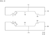
- FIG. 2 is a schematic cross-sectional view illustrating the sealing device for the pouch-type battery according to an embodiment of the present invention.
- the sealing device 10 includes the upper sealing block 100 and the lower sealing block 200.
- the sealing grooves 130 and 230 formed in two stages are formed in the upper sealing block 100 and the lower sealing block 200.
- the upper sealing block 100 is provided with a two-stage upper sealing groove 130 including a first upper step 110 forming a bottom surface and a second upper step 120 formed between the first upper step 110 and a surface thereof.
- the bottom surface means a lowermost surface
- the surface means an uppermost surface, with respect to a direction in which the upper sealing groove 130 is viewed inward.
- the lower sealing block 200 is provided with the lower sealing groove 230 formed in two stages.
- the lower sealing groove 230 includes a first lower step 210 forming the bottom surface and a second lower step 220 formed between the first lower step 210 and the surface.
- the upper sealing groove 130 formed in the upper sealing block 100 and the lower sealing groove 230 formed in the lower sealing block 200 have different step heights.
- a height A2 of the first lower step is greater than a height A1 of the first upper step (A1 ⁇ A2).
- a height B1 of the second upper step and a height B2 of the second lower step are similarly equal to each other, and a difference therebetween is 10 ⁇ m or less.
- the height A1 of the first upper step formed in the upper sealing block 100 is 240 ⁇ m, and the height B1 of the second upper step is 76 ⁇ m.
- the height A2 of the first lower step formed in the lower sealing block 200 is 260 ⁇ m, and the height B2 of the second lower step is 76 ⁇ m.
- This state is different from a sealing device according to the related art in which upper and lower sealing blocks are symmetrical to each other.
- the heights of the first upper step and the first lower step are controlled equally to a level of 250 ⁇ m.
- An embodiment of the present invention is differentiated in that the height A1 of the first upper step is lowered and the height A2 of the first lower step is increased.
- FIG. 3 is a schematic diagram illustrating a process of sealing an electrode lead formation part of the pouch-type battery using the sealing device for the pouch-type battery according to an embodiment of the present invention.
- the first upper step 110 of the upper sealing block 100 corresponds to an upper portion of the electrode lead 300 surrounded by the lead film 310.
- the second upper step 120 extends laterally from the electrode lead 300 and corresponds to an upper portion of the remaining lead film 310.
- the first lower step 210 of the lower sealing block 200 corresponds to a lower portion of the electrode lead 300 surrounded by the lead film 310, and the second lower step 220 extends laterally from the electrode lead 300 and corresponds to a lower portion of the remaining lead film 310.
- FIG. 4 is a schematic diagram illustrating a pouch-type battery 500 sealed by the sealing device for the pouch-type battery according to an embodiment of the present invention
- FIG. 5 is a partially enlarged view of a cross section A-A' in the pouch-type battery 500 of FIG. 4 .
- the pouch-type battery 500 has a structure in which a pouch-type battery case 440 surrounds the electrode assembly accommodated therein and the electrode lead 300 extending from the electrode tab protrudes outward.
- the lead film 310 is positioned between the electrode lead 300 and the pouch-type battery case 440.
- the pouch-type battery case 440 includes the upper pouch 400 and the lower pouch 401, and an edge thereof is sealed.
- FIG. 5 illustrates a cross section of a sealing area of the electrode lead 300.
- the upper pouch 400 and the lower pouch 401 each have three-layered structures including first resin layers 410 and 411 formed therein, aluminum layers 420 and 421, and second resin layers 430 and 431 formed on the outside. Further, the electrode lead 300 has a structure surrounded by the lead film 310.
- the safety of the battery is maximized by minimizing the reduction in the thickness of the first resin layer 411 in the lower pouch 401.
- the pouch-type battery was sealed using the sealing device illustrated in FIG. 2 .
- the sealing was performed with respect to an area in which the electrode lead is formed.
- a heating temperature was 180 °C, and detailed specifications of the sealing device are summarized in Table 1 below.
- the pouch applied to the pouch-type battery has a three-layered structure including a PP layer, an aluminum layer, and a PET layer.
- the total thickness of the pouch is 155 ⁇ m, and the thickness of the PP resin layer among them is 80 ⁇ m.
- the pouch-type battery was sealed in the same manner as the example except that specifications of the sealing device were changed to Table 1 below.
- Table 1 Classification Height of step Example Comparative Example Upper sealing block Height ( ⁇ m) of first upper step A1 76 76 Height ( ⁇ m) of second upper step B1 240 250 Lower sealing block Height ( ⁇ m) of first lower upper step A2 76 76 Height ( ⁇ m) of second lower step B2 260 250
- a residual ratio of the PP layer was evaluated.
- the PP residual rate (%) was calculated by comparing the thickness of the PP layer before sealing with the thickness of the PP layer after sealing.
- the PP residual ratio in the lower pouch reaches 30%.
- the lower pouch is first widened among the electrode lead sealing part.
- Embodiments of the present invention increases the safety of the pouch-type battery by maximizing the PP residual ratio in the lower pouch in the electrode lead sealing part.
- the PP residual ratio in the upper pouch was as low as 16%.
- the upper pouch is heat-sealed more strongly, and thus the PP residual ratio in the upper pouch is reduced.
- Sealing strength evaluation a force is measured at a point at which the electrode lead sealing part is damaged by vertically applying a force under room temperature conditions.
- Pressure-resistant strength is measured under a condition of 60 °C, and particularly, a pressure is measured at a point at which the electrode lead sealing part is damaged by forming a hole on one side of the sealed pouch-type battery and injecting an inert gas (Ar) thereinto.
- Ar inert gas
Landscapes
- Chemical & Material Sciences (AREA)
- Chemical Kinetics & Catalysis (AREA)
- Electrochemistry (AREA)
- General Chemical & Material Sciences (AREA)
- Engineering & Computer Science (AREA)
- Mechanical Engineering (AREA)
- Inorganic Chemistry (AREA)
- Manufacturing & Machinery (AREA)
- Sealing Battery Cases Or Jackets (AREA)
Claims (12)
- Dispositif de scellage (10) pour une batterie de type poche (500) comprenant :un bloc de scellage supérieur (100) ayant une rainure de scellage supérieure à deux étages (130), la rainure de scellage supérieure à deux étages (130) comportant un premier gradin supérieur (110) configuré pour former une première surface de l'étui de batterie de type poche (440) et un second gradin supérieur (120) disposé entre le premier gradin supérieur (110) et un bloc de scellage inférieur (200) ; etle bloc de scellage inférieur (200) ayant une rainure de scellage inférieure à deux étages (230), la rainure de scellage inférieure à deux étages (230) comportant un premier gradin inférieur (210) configuré pour former une seconde surface de l'étui de batterie de type poche (440) et un second gradin inférieur (220) disposé entre le premier gradin inférieur (210) et le bloc de scellage supérieur (100),dans lequel le bloc de scellage supérieur (100) est configuré pour être en contact avec une première surface d'une partie de scellage de conducteur d'électrode de la batterie de type poche (500), et le bloc de scellage inférieur (200) est configuré pour être en contact avec une seconde surface de la partie de scellage de conducteur d'électrode de la batterie de type poche, dans lequel le bloc de scellage inférieur (200) est espacé du bloc de scellage supérieur (100) et fait face à celui-ci, etcaractérisé en ce que la Condition 1 est satisfaite,
 dans laquelle B1 représente une différence de profondeur moyenne entre le premier gradin supérieur (110) etle second gradin supérieur (120) dans le bloc de scellage supérieur (100), et B2 représente une différence de profondeur moyenne entre le premier gradin inférieur (210) et le second gradin inférieur (220) dans le bloc de scellage inférieur (200).
 - Dispositif de scellage selon la revendication 1, dans lequel la différence de profondeur moyenne B1 entre le premier gradin supérieur (110) et le second gradin supérieur (120) est dans une plage de 200 µm à 280 µm, et
dans lequel la différence de profondeur moyenne B2 entre le premier gradin inférieur (210) et le second gradin inférieur (220) est dans une plage de 220 µm à 320 µm. - Dispositif de scellage selon la revendication 1, dans lequel une différence entre une profondeur moyenne A1 du second gradin supérieur (120) et une profondeur moyenne A2 du second gradin inférieur (220) est de 10 µm ou moins.
- Dispositif de scellage selon la revendication 3, dans lequel la profondeur moyenne A1 du second gradin supérieur (120) et la profondeur moyenne A2 du second gradin inférieur (220) sont dans une plage de 40 µm à 100 µm.
- Dispositif de scellage selon la revendication 1, dans lequel les blocs de scellage supérieur et inférieur (100, 200) sont configurés pour presser et chauffer la partie de scellage de conducteur d'électrode (300) de la batterie de type poche (500) par les deux côtés de celle-ci, et dans lequel une température de chauffage est dans une plage de 110 °C à 200 °C.
- Batterie de type poche (500) comprenant :un ensemble d'électrodes ;un conducteur d'électrode (300) faisant saillie à partir de l'ensemble d'électrodes ;une poche supérieure (400) et une poche inférieure (401) configurées pour accueillir l'ensemble d'électrodes ; etune partie de scellage d'électrode,dans laquelle la partie de scellage d'électrode possède une structure, dans laquelle la structure comporte les poches supérieure et inférieure (400, 401) configurées pour envelopper l'ensemble d'électrodes de sorte que le conducteur d'électrode (300) de l'ensemble d'électrodes fasse saillie à partir de l'élément de batterie de type poche (500), caractérisée en ce que la Condition 2 est satisfaite,
 dans laquelle T1 représente une épaisseur moyenne de la poche supérieure (400) dans la partie de scellage de conducteur d'électrode disposée sur une première surface du conducteur d'électrode (300), etdans laquelle T2 représente une épaisseur moyenne de la poche inférieure (401) dans la partie de scellage de conducteur d'électrode disposée sur une seconde surface du conducteur d'électrode (300).
 - Batterie de type poche (500) selon la revendication 6, dans laquelle T1 est dans une plage de 80 µm à 90 µm, et dans laquelle T2 est dans une plage de 91 µm à 105 µm.
- Batterie de type poche (500) selon la revendication 6, dans laquelle chacune des poches supérieure et inférieure (400, 401) comporte :une première couche de résine (410, 411) positionnée sur une surface interne de celle-ci ;une couche métallique ; etune seconde couche de résine (430, 431) positionnée sur une surface externe de celle-ci,dans laquelle, dans la partie de scellage de conducteur d'électrode, un rapport d'une épaisseur de la première couche de résine (410) de la poche supérieure (400) sur une épaisseur totale de la poche supérieure (400) est dans une plage de 10 % à 18 %, etdans laquelle, dans la partie de scellage de conducteur d'électrode, un rapport d'une épaisseur de la première couche de résine (411) de la poche inférieure (401) sur une épaisseur totale de la poche inférieure (401) est dans une plage de 20 % à 30 %.
- Batterie de type poche (500) selon la revendication 8,dans laquelle une épaisseur moyenne de la première couche de résine (410) de la poche supérieure (400) dans la partie de scellage de conducteur d'électrode est dans une plage de 8 µm à 17 µm, etdans laquelle une épaisseur moyenne de la première couche de résine (411) de la poche inférieure (401) dans la partie de scellage de conducteur d'électrode est dans une plage de 20 µm à 30 µm.
- Batterie de type poche (500) selon la revendication 8 comportant en outre une zone de non scellage configurée pour accueillir l'ensemble d'électrodes,dans laquelle la zone de non scellage n'est pas scellée entre les poches supérieure et inférieure (400, 401), etdans laquelle une épaisseur moyenne de la première couche de résine (410, 411) de chacune des poches supérieure et inférieure (400, 401) dans la zone de non scellage est dans une plage de 50 µm à 100 µm.
- Batterie de type poche (500) selon la revendication 6, dans laquelle chacune des poches supérieure et inférieure (400, 401) comporte :une première couche de résine (410, 411) ayant une résine de polypropylène,une couche métallique (420, 421) ayant de l'aluminium ou un alliage d'aluminium, etune seconde couche de résine (430, 431) ayant une résine de polyéthylène téréphtalate (PET).
- Batterie de type poche (500) selon la revendication 6, dans laquelle l'ensemble d'électrodes est un ensemble d'électrodes de type à empilement.
Applications Claiming Priority (2)
| Application Number | Priority Date | Filing Date | Title |
|---|---|---|---|
| KR20210167905 | 2021-11-30 | ||
| PCT/KR2022/018218 WO2023101278A1 (fr) | 2021-11-30 | 2022-11-17 | Batterie de type poche et dispositif d'étanchéité pour batterie de type poche |
Publications (3)
| Publication Number | Publication Date |
|---|---|
| EP4261016A1 EP4261016A1 (fr) | 2023-10-18 |
| EP4261016A4 EP4261016A4 (fr) | 2024-08-07 |
| EP4261016B1 true EP4261016B1 (fr) | 2025-05-07 |
Family
ID=86612684
Family Applications (1)
| Application Number | Title | Priority Date | Filing Date |
|---|---|---|---|
| EP22901636.5A Active EP4261016B1 (fr) | 2021-11-30 | 2022-11-17 | Batterie de type poche et dispositif de scellage pour batterie de type poche |
Country Status (8)
| Country | Link |
|---|---|
| US (1) | US20240120580A1 (fr) |
| EP (1) | EP4261016B1 (fr) |
| JP (1) | JP2024503375A (fr) |
| KR (1) | KR20230081633A (fr) |
| CN (1) | CN116723926B (fr) |
| ES (1) | ES3030548T3 (fr) |
| HU (1) | HUE071481T2 (fr) |
| WO (1) | WO2023101278A1 (fr) |
Families Citing this family (2)
| Publication number | Priority date | Publication date | Assignee | Title |
|---|---|---|---|---|
| KR102903130B1 (ko) * | 2023-08-16 | 2025-12-22 | 주식회사 엘지에너지솔루션 | 실링 장치 |
| TR2023019970A1 (tr) * | 2023-12-30 | 2025-07-21 | Intecro Robotik Otomasyon Ar Ge Muehendislik Makine Sanayi Ve Ticaret Anonim Sirketi | Li̇-i̇on batarya poşet ti̇pi̇ hücre modülleri̇nde isiyla plasti̇k bi̇rleşti̇rme si̇stemi̇ |
Family Cites Families (11)
| Publication number | Priority date | Publication date | Assignee | Title |
|---|---|---|---|---|
| JP5793788B2 (ja) * | 2009-05-21 | 2015-10-14 | エルジー ケム. エルティーディ. | 耐水性パウチ型二次電池 |
| KR101452021B1 (ko) * | 2010-10-14 | 2014-10-23 | 주식회사 엘지화학 | 파우치형 이차 전지의 실링장치 |
| KR101487092B1 (ko) * | 2012-07-11 | 2015-01-27 | 주식회사 엘지화학 | 이차전지용 파우치 및 이를 포함하는 이차전지 |
| JP6090473B2 (ja) * | 2012-12-28 | 2017-03-08 | エルジー・ケム・リミテッド | 二次電池のパウチケースシール装置及びシール方法 |
| KR20160096417A (ko) * | 2015-02-05 | 2016-08-16 | 주식회사 엘지화학 | 2차 전지의 파우치 실링 장치 및 실링 방법 |
| KR101852250B1 (ko) * | 2015-04-02 | 2018-04-26 | 주식회사 엘지화학 | 파우치형 이차전지의 실링 장치 |
| KR101947149B1 (ko) | 2015-12-16 | 2019-02-13 | 주식회사 엘지화학 | 가압과 열 인가 면적이 증대된 전지케이스의 밀봉 장치 |
| PL3373374T3 (pl) * | 2016-09-28 | 2019-12-31 | Lg Chem, Ltd. | Sposób uszczelniania obudowy pakietowej akumulatora |
| US10446803B2 (en) * | 2017-08-29 | 2019-10-15 | Robert Bosch Battery Systems Llc | Lead tab for battery terminal |
| KR102448131B1 (ko) * | 2017-08-29 | 2022-09-28 | 주식회사 엘지에너지솔루션 | 부분적으로 증가된 두께를 가지는 라미네이트 시트로 이루어진 파우치형 이차전지 |
| HUE073149T2 (hu) * | 2018-11-13 | 2026-01-28 | Lg Energy Solution Ltd | Tasakburkolat és eljárás ilyen tasakburkolattal ellátott tasak típusú szekunder akkumulátor elõállítására |
-
2022
- 2022-11-17 JP JP2023541594A patent/JP2024503375A/ja active Pending
- 2022-11-17 WO PCT/KR2022/018218 patent/WO2023101278A1/fr not_active Ceased
- 2022-11-17 HU HUE22901636A patent/HUE071481T2/hu unknown
- 2022-11-17 ES ES22901636T patent/ES3030548T3/es active Active
- 2022-11-17 US US18/272,929 patent/US20240120580A1/en active Pending
- 2022-11-17 EP EP22901636.5A patent/EP4261016B1/fr active Active
- 2022-11-17 CN CN202280010453.5A patent/CN116723926B/zh active Active
- 2022-11-17 KR KR1020220154510A patent/KR20230081633A/ko active Pending
Also Published As
| Publication number | Publication date |
|---|---|
| US20240120580A1 (en) | 2024-04-11 |
| CN116723926A (zh) | 2023-09-08 |
| HUE071481T2 (hu) | 2025-08-28 |
| EP4261016A1 (fr) | 2023-10-18 |
| CN116723926B (zh) | 2026-04-24 |
| EP4261016A4 (fr) | 2024-08-07 |
| WO2023101278A1 (fr) | 2023-06-08 |
| ES3030548T3 (en) | 2025-06-30 |
| JP2024503375A (ja) | 2024-01-25 |
| KR20230081633A (ko) | 2023-06-07 |
Similar Documents
| Publication | Publication Date | Title |
|---|---|---|
| CN101512821B (zh) | 包含单向排气阀的二次电池 | |
| KR100708023B1 (ko) | 필름 외장 전기 디바이스 및 그 제조 방법 | |
| EP3249732B1 (fr) | Appareil d'étanchéité de batterie rechargeable de type pochette | |
| JP4232038B2 (ja) | フィルム外装電気デバイスおよびその製造方法 | |
| US20090263703A1 (en) | Cap assembly and secondary battery using the same | |
| EP4261016B1 (fr) | Batterie de type poche et dispositif de scellage pour batterie de type poche | |
| KR20100126226A (ko) | 내수성 파우치형 이차전지 | |
| KR20190042801A (ko) | 균열을 방지하기 위한 파우치형 이차전지용 실링 블록, 이를 사용하여 제조되는 파우치형 전지케이스 및 파우치형 전지케이스의 실링 방법 | |
| EP4191761B1 (fr) | Cellule de batterie et appareil de fabrication de cellule de batterie | |
| US20240145830A1 (en) | Pouch-Type Secondary Battery and Manufacturing Method Therefor | |
| KR102761907B1 (ko) | 이차 전지 | |
| KR102010443B1 (ko) | 내전해성이 우수한 이차전지용 캡조립체 | |
| EP4231428A1 (fr) | Batterie secondaire | |
| US20230155221A1 (en) | Pouch-Shaped Battery Cell Manufacturing Method Including Secondary Sealing and Pouch-Shaped Battery Cell Manufactured Thereby | |
| JP7187927B2 (ja) | 蓄電デバイス | |
| EP4712221A1 (fr) | Batterie et procédé de fabrication de la batterie | |
| EP4651280A1 (fr) | Batterie secondaire et dispositif d'étanchéité destiné à la fabriquer | |
| KR102961141B1 (ko) | 파우치형 전지 케이스 및 이를 포함하는 이차 전지 | |
| KR102082655B1 (ko) | 모서리가 절취되어 있는 구조의 전극조립체 제조방법 및 이를 사용하여 제조되는 전극조립체 | |
| EP4687209A1 (fr) | Batterie secondaire | |
| KR102558420B1 (ko) | 이차전지 | |
| CA3285692A1 (fr) | Batterie secondaire et dispositif d'étanchéité destiné à la fabriquer | |
| KR20250143199A (ko) | 파우치 포밍 장치 및 방법 | |
| KR20260034591A (ko) | 이차 전지 | |
| KR20230082217A (ko) | 파우치형 이차전지 |
Legal Events
| Date | Code | Title | Description |
|---|---|---|---|
| STAA | Information on the status of an ep patent application or granted ep patent |
Free format text: STATUS: THE INTERNATIONAL PUBLICATION HAS BEEN MADE |
|
| PUAI | Public reference made under article 153(3) epc to a published international application that has entered the european phase |
Free format text: ORIGINAL CODE: 0009012 |
|
| STAA | Information on the status of an ep patent application or granted ep patent |
Free format text: STATUS: REQUEST FOR EXAMINATION WAS MADE |
|
| 17P | Request for examination filed |
Effective date: 20230710 |
|
| AK | Designated contracting states |
Kind code of ref document: A1 Designated state(s): AL AT BE BG CH CY CZ DE DK EE ES FI FR GB GR HR HU IE IS IT LI LT LU LV MC ME MK MT NL NO PL PT RO RS SE SI SK SM TR |
|
| REG | Reference to a national code |
Ref country code: DE Ref legal event code: R079 Free format text: PREVIOUS MAIN CLASS: B29C0065000000 Ipc: B29C0065180000 Ref document number: 602022014484 Country of ref document: DE |
|
| A4 | Supplementary search report drawn up and despatched |
Effective date: 20240704 |
|
| RIC1 | Information provided on ipc code assigned before grant |
Ipc: B29L 31/34 20060101ALN20240628BHEP Ipc: B29L 31/00 20060101ALI20240628BHEP Ipc: B29C 65/02 20060101ALI20240628BHEP Ipc: H01M 50/105 20210101ALI20240628BHEP Ipc: H01M 50/129 20210101ALI20240628BHEP Ipc: H01M 50/178 20210101ALI20240628BHEP Ipc: B29C 65/18 20060101AFI20240628BHEP |
|
| GRAP | Despatch of communication of intention to grant a patent |
Free format text: ORIGINAL CODE: EPIDOSNIGR1 |
|
| STAA | Information on the status of an ep patent application or granted ep patent |
Free format text: STATUS: GRANT OF PATENT IS INTENDED |
|
| DAV | Request for validation of the european patent (deleted) | ||
| DAX | Request for extension of the european patent (deleted) | ||
| RIC1 | Information provided on ipc code assigned before grant |
Ipc: B29K 705/02 20060101ALN20250204BHEP Ipc: B29L 31/34 20060101ALN20250204BHEP Ipc: H01M 50/188 20210101ALI20250204BHEP Ipc: H01M 50/121 20210101ALI20250204BHEP Ipc: H01M 50/119 20210101ALI20250204BHEP Ipc: B29C 65/00 20060101ALI20250204BHEP Ipc: B29L 31/00 20060101ALI20250204BHEP Ipc: B29C 65/02 20060101ALI20250204BHEP Ipc: H01M 50/105 20210101ALI20250204BHEP Ipc: H01M 50/129 20210101ALI20250204BHEP Ipc: H01M 50/178 20210101ALI20250204BHEP Ipc: B29C 65/18 20060101AFI20250204BHEP |
|
| RIC1 | Information provided on ipc code assigned before grant |
Ipc: B29K 705/02 20060101ALN20250212BHEP Ipc: B29L 31/34 20060101ALN20250212BHEP Ipc: H01M 50/188 20210101ALI20250212BHEP Ipc: H01M 50/121 20210101ALI20250212BHEP Ipc: H01M 50/119 20210101ALI20250212BHEP Ipc: B29C 65/00 20060101ALI20250212BHEP Ipc: B29L 31/00 20060101ALI20250212BHEP Ipc: B29C 65/02 20060101ALI20250212BHEP Ipc: H01M 50/105 20210101ALI20250212BHEP Ipc: H01M 50/129 20210101ALI20250212BHEP Ipc: H01M 50/178 20210101ALI20250212BHEP Ipc: B29C 65/18 20060101AFI20250212BHEP |
|
| RIC1 | Information provided on ipc code assigned before grant |
Ipc: B29L 31/00 20060101ALN20250217BHEP Ipc: B29K 705/02 20060101ALN20250217BHEP Ipc: B29L 31/34 20060101ALN20250217BHEP Ipc: H01M 50/188 20210101ALI20250217BHEP Ipc: H01M 50/121 20210101ALI20250217BHEP Ipc: H01M 50/119 20210101ALI20250217BHEP Ipc: B29C 65/00 20060101ALI20250217BHEP Ipc: B29C 65/02 20060101ALI20250217BHEP Ipc: H01M 50/105 20210101ALI20250217BHEP Ipc: H01M 50/129 20210101ALI20250217BHEP Ipc: H01M 50/178 20210101ALI20250217BHEP Ipc: B29C 65/18 20060101AFI20250217BHEP |
|
| GRAS | Grant fee paid |
Free format text: ORIGINAL CODE: EPIDOSNIGR3 |
|
| INTG | Intention to grant announced |
Effective date: 20250228 |
|
| GRAA | (expected) grant |
Free format text: ORIGINAL CODE: 0009210 |
|
| STAA | Information on the status of an ep patent application or granted ep patent |
Free format text: STATUS: THE PATENT HAS BEEN GRANTED |
|
| P01 | Opt-out of the competence of the unified patent court (upc) registered |
Free format text: CASE NUMBER: APP_13996/2025 Effective date: 20250321 |
|
| AK | Designated contracting states |
Kind code of ref document: B1 Designated state(s): AL AT BE BG CH CY CZ DE DK EE ES FI FR GB GR HR HU IE IS IT LI LT LU LV MC ME MK MT NL NO PL PT RO RS SE SI SK SM TR |
|
| REG | Reference to a national code |
Ref country code: GB Ref legal event code: FG4D |
|
| REG | Reference to a national code |
Ref country code: CH Ref legal event code: EP |
|
| REG | Reference to a national code |
Ref country code: IE Ref legal event code: FG4D |
|
| REG | Reference to a national code |
Ref country code: DE Ref legal event code: R096 Ref document number: 602022014484 Country of ref document: DE |
|
| REG | Reference to a national code |
Ref country code: ES Ref legal event code: FG2A Ref document number: 3030548 Country of ref document: ES Kind code of ref document: T3 Effective date: 20250630 |
|
| REG | Reference to a national code |
Ref country code: HU Ref legal event code: AG4A Ref document number: E071481 Country of ref document: HU |
|
| REG | Reference to a national code |
Ref country code: NL Ref legal event code: MP Effective date: 20250507 |
|
| PG25 | Lapsed in a contracting state [announced via postgrant information from national office to epo] |
Ref country code: FI Free format text: LAPSE BECAUSE OF FAILURE TO SUBMIT A TRANSLATION OF THE DESCRIPTION OR TO PAY THE FEE WITHIN THE PRESCRIBED TIME-LIMIT Effective date: 20250507 Ref country code: PT Free format text: LAPSE BECAUSE OF FAILURE TO SUBMIT A TRANSLATION OF THE DESCRIPTION OR TO PAY THE FEE WITHIN THE PRESCRIBED TIME-LIMIT Effective date: 20250908 |
|
| REG | Reference to a national code |
Ref country code: LT Ref legal event code: MG9D |
|
| PG25 | Lapsed in a contracting state [announced via postgrant information from national office to epo] |
Ref country code: GR Free format text: LAPSE BECAUSE OF FAILURE TO SUBMIT A TRANSLATION OF THE DESCRIPTION OR TO PAY THE FEE WITHIN THE PRESCRIBED TIME-LIMIT Effective date: 20250808 Ref country code: NO Free format text: LAPSE BECAUSE OF FAILURE TO SUBMIT A TRANSLATION OF THE DESCRIPTION OR TO PAY THE FEE WITHIN THE PRESCRIBED TIME-LIMIT Effective date: 20250807 |
|
| PG25 | Lapsed in a contracting state [announced via postgrant information from national office to epo] |
Ref country code: PL Free format text: LAPSE BECAUSE OF FAILURE TO SUBMIT A TRANSLATION OF THE DESCRIPTION OR TO PAY THE FEE WITHIN THE PRESCRIBED TIME-LIMIT Effective date: 20250507 Ref country code: NL Free format text: LAPSE BECAUSE OF FAILURE TO SUBMIT A TRANSLATION OF THE DESCRIPTION OR TO PAY THE FEE WITHIN THE PRESCRIBED TIME-LIMIT Effective date: 20250507 |
|
| REG | Reference to a national code |
Ref country code: AT Ref legal event code: MK05 Ref document number: 1792021 Country of ref document: AT Kind code of ref document: T Effective date: 20250507 |
|
| PG25 | Lapsed in a contracting state [announced via postgrant information from national office to epo] |
Ref country code: BG Free format text: LAPSE BECAUSE OF FAILURE TO SUBMIT A TRANSLATION OF THE DESCRIPTION OR TO PAY THE FEE WITHIN THE PRESCRIBED TIME-LIMIT Effective date: 20250507 |
|
| PG25 | Lapsed in a contracting state [announced via postgrant information from national office to epo] |
Ref country code: HR Free format text: LAPSE BECAUSE OF FAILURE TO SUBMIT A TRANSLATION OF THE DESCRIPTION OR TO PAY THE FEE WITHIN THE PRESCRIBED TIME-LIMIT Effective date: 20250507 |
|
| PG25 | Lapsed in a contracting state [announced via postgrant information from national office to epo] |
Ref country code: AT Free format text: LAPSE BECAUSE OF FAILURE TO SUBMIT A TRANSLATION OF THE DESCRIPTION OR TO PAY THE FEE WITHIN THE PRESCRIBED TIME-LIMIT Effective date: 20250507 |
|
| PG25 | Lapsed in a contracting state [announced via postgrant information from national office to epo] |
Ref country code: RS Free format text: LAPSE BECAUSE OF FAILURE TO SUBMIT A TRANSLATION OF THE DESCRIPTION OR TO PAY THE FEE WITHIN THE PRESCRIBED TIME-LIMIT Effective date: 20250807 |
|
| PG25 | Lapsed in a contracting state [announced via postgrant information from national office to epo] |
Ref country code: IS Free format text: LAPSE BECAUSE OF FAILURE TO SUBMIT A TRANSLATION OF THE DESCRIPTION OR TO PAY THE FEE WITHIN THE PRESCRIBED TIME-LIMIT Effective date: 20250907 |
|
| PG25 | Lapsed in a contracting state [announced via postgrant information from national office to epo] |
Ref country code: LV Free format text: LAPSE BECAUSE OF FAILURE TO SUBMIT A TRANSLATION OF THE DESCRIPTION OR TO PAY THE FEE WITHIN THE PRESCRIBED TIME-LIMIT Effective date: 20250507 |
|
| PGFP | Annual fee paid to national office [announced via postgrant information from national office to epo] |
Ref country code: HU Payment date: 20251127 Year of fee payment: 4 |
|
| PGFP | Annual fee paid to national office [announced via postgrant information from national office to epo] |
Ref country code: DE Payment date: 20251020 Year of fee payment: 4 |
|
| PG25 | Lapsed in a contracting state [announced via postgrant information from national office to epo] |
Ref country code: SM Free format text: LAPSE BECAUSE OF FAILURE TO SUBMIT A TRANSLATION OF THE DESCRIPTION OR TO PAY THE FEE WITHIN THE PRESCRIBED TIME-LIMIT Effective date: 20250507 Ref country code: DK Free format text: LAPSE BECAUSE OF FAILURE TO SUBMIT A TRANSLATION OF THE DESCRIPTION OR TO PAY THE FEE WITHIN THE PRESCRIBED TIME-LIMIT Effective date: 20250507 |
|
| PGFP | Annual fee paid to national office [announced via postgrant information from national office to epo] |
Ref country code: FR Payment date: 20251021 Year of fee payment: 4 |
|
| PGFP | Annual fee paid to national office [announced via postgrant information from national office to epo] |
Ref country code: BE Payment date: 20251020 Year of fee payment: 4 |
|
| PG25 | Lapsed in a contracting state [announced via postgrant information from national office to epo] |
Ref country code: CZ Free format text: LAPSE BECAUSE OF FAILURE TO SUBMIT A TRANSLATION OF THE DESCRIPTION OR TO PAY THE FEE WITHIN THE PRESCRIBED TIME-LIMIT Effective date: 20250507 |
|
| PG25 | Lapsed in a contracting state [announced via postgrant information from national office to epo] |
Ref country code: EE Free format text: LAPSE BECAUSE OF FAILURE TO SUBMIT A TRANSLATION OF THE DESCRIPTION OR TO PAY THE FEE WITHIN THE PRESCRIBED TIME-LIMIT Effective date: 20250507 |
|
| PG25 | Lapsed in a contracting state [announced via postgrant information from national office to epo] |
Ref country code: SK Free format text: LAPSE BECAUSE OF FAILURE TO SUBMIT A TRANSLATION OF THE DESCRIPTION OR TO PAY THE FEE WITHIN THE PRESCRIBED TIME-LIMIT Effective date: 20250507 |
|
| PG25 | Lapsed in a contracting state [announced via postgrant information from national office to epo] |
Ref country code: IT Free format text: LAPSE BECAUSE OF FAILURE TO SUBMIT A TRANSLATION OF THE DESCRIPTION OR TO PAY THE FEE WITHIN THE PRESCRIBED TIME-LIMIT Effective date: 20250507 |
|
| PGFP | Annual fee paid to national office [announced via postgrant information from national office to epo] |
Ref country code: ES Payment date: 20251215 Year of fee payment: 4 |
|
| REG | Reference to a national code |
Ref country code: DE Ref legal event code: R097 Ref document number: 602022014484 Country of ref document: DE |
|
| PG25 | Lapsed in a contracting state [announced via postgrant information from national office to epo] |
Ref country code: RO Free format text: LAPSE BECAUSE OF FAILURE TO SUBMIT A TRANSLATION OF THE DESCRIPTION OR TO PAY THE FEE WITHIN THE PRESCRIBED TIME-LIMIT Effective date: 20250507 |
|
| PLBE | No opposition filed within time limit |
Free format text: ORIGINAL CODE: 0009261 |
|
| STAA | Information on the status of an ep patent application or granted ep patent |
Free format text: STATUS: NO OPPOSITION FILED WITHIN TIME LIMIT |
|
| REG | Reference to a national code |
Ref country code: CH Ref legal event code: L10 Free format text: ST27 STATUS EVENT CODE: U-0-0-L10-L00 (AS PROVIDED BY THE NATIONAL OFFICE) Effective date: 20260318 |
|
| 26N | No opposition filed |
Effective date: 20260210 |