EP4261029B1 - Machine pour la fabrication d'un plateau en carton - Google Patents
Machine pour la fabrication d'un plateau en carton Download PDFInfo
- Publication number
- EP4261029B1 EP4261029B1 EP22168670.2A EP22168670A EP4261029B1 EP 4261029 B1 EP4261029 B1 EP 4261029B1 EP 22168670 A EP22168670 A EP 22168670A EP 4261029 B1 EP4261029 B1 EP 4261029B1
- Authority
- EP
- European Patent Office
- Prior art keywords
- robot
- tray
- frames
- trays
- blanks
- Prior art date
- Legal status (The legal status is an assumption and is not a legal conclusion. Google has not performed a legal analysis and makes no representation as to the accuracy of the status listed.)
- Active
Links
Images


Classifications
-
- B—PERFORMING OPERATIONS; TRANSPORTING
- B31—MAKING ARTICLES OF PAPER, CARDBOARD OR MATERIAL WORKED IN A MANNER ANALOGOUS TO PAPER; WORKING PAPER, CARDBOARD OR MATERIAL WORKED IN A MANNER ANALOGOUS TO PAPER
- B31B—MAKING CONTAINERS OF PAPER, CARDBOARD OR MATERIAL WORKED IN A MANNER ANALOGOUS TO PAPER
- B31B50/00—Making rigid or semi-rigid containers, e.g. boxes or cartons
- B31B50/02—Feeding or positioning sheets, blanks or webs
- B31B50/04—Feeding sheets or blanks
-
- B—PERFORMING OPERATIONS; TRANSPORTING
- B31—MAKING ARTICLES OF PAPER, CARDBOARD OR MATERIAL WORKED IN A MANNER ANALOGOUS TO PAPER; WORKING PAPER, CARDBOARD OR MATERIAL WORKED IN A MANNER ANALOGOUS TO PAPER
- B31B—MAKING CONTAINERS OF PAPER, CARDBOARD OR MATERIAL WORKED IN A MANNER ANALOGOUS TO PAPER
- B31B50/00—Making rigid or semi-rigid containers, e.g. boxes or cartons
- B31B50/26—Folding sheets, blanks or webs
- B31B50/44—Folding sheets, blanks or webs by plungers moving through folding dies
-
- B—PERFORMING OPERATIONS; TRANSPORTING
- B31—MAKING ARTICLES OF PAPER, CARDBOARD OR MATERIAL WORKED IN A MANNER ANALOGOUS TO PAPER; WORKING PAPER, CARDBOARD OR MATERIAL WORKED IN A MANNER ANALOGOUS TO PAPER
- B31B—MAKING CONTAINERS OF PAPER, CARDBOARD OR MATERIAL WORKED IN A MANNER ANALOGOUS TO PAPER
- B31B50/00—Making rigid or semi-rigid containers, e.g. boxes or cartons
- B31B50/60—Uniting opposed surfaces or edges; Taping
- B31B50/62—Uniting opposed surfaces or edges; Taping by adhesives
- B31B50/624—Applying glue on blanks
-
- B—PERFORMING OPERATIONS; TRANSPORTING
- B31—MAKING ARTICLES OF PAPER, CARDBOARD OR MATERIAL WORKED IN A MANNER ANALOGOUS TO PAPER; WORKING PAPER, CARDBOARD OR MATERIAL WORKED IN A MANNER ANALOGOUS TO PAPER
- B31B—MAKING CONTAINERS OF PAPER, CARDBOARD OR MATERIAL WORKED IN A MANNER ANALOGOUS TO PAPER
- B31B2105/00—Rigid or semi-rigid containers made by assembling separate sheets, blanks or webs
- B31B2105/002—Making boxes characterised by the shape of the blanks from which they are formed
- B31B2105/0024—Making boxes having all side walls attached to the bottom
-
- B—PERFORMING OPERATIONS; TRANSPORTING
- B31—MAKING ARTICLES OF PAPER, CARDBOARD OR MATERIAL WORKED IN A MANNER ANALOGOUS TO PAPER; WORKING PAPER, CARDBOARD OR MATERIAL WORKED IN A MANNER ANALOGOUS TO PAPER
- B31B—MAKING CONTAINERS OF PAPER, CARDBOARD OR MATERIAL WORKED IN A MANNER ANALOGOUS TO PAPER
- B31B2110/00—Shape of rigid or semi-rigid containers
- B31B2110/10—Shape of rigid or semi-rigid containers having a cross section of varying size or shape, e.g. conical or pyramidal
-
- B—PERFORMING OPERATIONS; TRANSPORTING
- B31—MAKING ARTICLES OF PAPER, CARDBOARD OR MATERIAL WORKED IN A MANNER ANALOGOUS TO PAPER; WORKING PAPER, CARDBOARD OR MATERIAL WORKED IN A MANNER ANALOGOUS TO PAPER
- B31B—MAKING CONTAINERS OF PAPER, CARDBOARD OR MATERIAL WORKED IN A MANNER ANALOGOUS TO PAPER
- B31B2110/00—Shape of rigid or semi-rigid containers
- B31B2110/30—Shape of rigid or semi-rigid containers having a polygonal cross section
- B31B2110/35—Shape of rigid or semi-rigid containers having a polygonal cross section rectangular, e.g. square
-
- B—PERFORMING OPERATIONS; TRANSPORTING
- B31—MAKING ARTICLES OF PAPER, CARDBOARD OR MATERIAL WORKED IN A MANNER ANALOGOUS TO PAPER; WORKING PAPER, CARDBOARD OR MATERIAL WORKED IN A MANNER ANALOGOUS TO PAPER
- B31B—MAKING CONTAINERS OF PAPER, CARDBOARD OR MATERIAL WORKED IN A MANNER ANALOGOUS TO PAPER
- B31B2120/00—Construction of rigid or semi-rigid containers
- B31B2120/002—Construction of rigid or semi-rigid containers having contracted or rolled necks, having shoulders
-
- B—PERFORMING OPERATIONS; TRANSPORTING
- B31—MAKING ARTICLES OF PAPER, CARDBOARD OR MATERIAL WORKED IN A MANNER ANALOGOUS TO PAPER; WORKING PAPER, CARDBOARD OR MATERIAL WORKED IN A MANNER ANALOGOUS TO PAPER
- B31B—MAKING CONTAINERS OF PAPER, CARDBOARD OR MATERIAL WORKED IN A MANNER ANALOGOUS TO PAPER
- B31B2120/00—Construction of rigid or semi-rigid containers
- B31B2120/50—Construction of rigid or semi-rigid containers covered or externally reinforced
-
- B—PERFORMING OPERATIONS; TRANSPORTING
- B31—MAKING ARTICLES OF PAPER, CARDBOARD OR MATERIAL WORKED IN A MANNER ANALOGOUS TO PAPER; WORKING PAPER, CARDBOARD OR MATERIAL WORKED IN A MANNER ANALOGOUS TO PAPER
- B31B—MAKING CONTAINERS OF PAPER, CARDBOARD OR MATERIAL WORKED IN A MANNER ANALOGOUS TO PAPER
- B31B2120/00—Construction of rigid or semi-rigid containers
- B31B2120/502—Construction of rigid or semi-rigid containers having integral corner posts or reinforcements
-
- B—PERFORMING OPERATIONS; TRANSPORTING
- B31—MAKING ARTICLES OF PAPER, CARDBOARD OR MATERIAL WORKED IN A MANNER ANALOGOUS TO PAPER; WORKING PAPER, CARDBOARD OR MATERIAL WORKED IN A MANNER ANALOGOUS TO PAPER
- B31B—MAKING CONTAINERS OF PAPER, CARDBOARD OR MATERIAL WORKED IN A MANNER ANALOGOUS TO PAPER
- B31B50/00—Making rigid or semi-rigid containers, e.g. boxes or cartons
- B31B50/02—Feeding or positioning sheets, blanks or webs
- B31B50/04—Feeding sheets or blanks
- B31B50/042—Feeding sheets or blanks using rolls, belts or chains
-
- B—PERFORMING OPERATIONS; TRANSPORTING
- B31—MAKING ARTICLES OF PAPER, CARDBOARD OR MATERIAL WORKED IN A MANNER ANALOGOUS TO PAPER; WORKING PAPER, CARDBOARD OR MATERIAL WORKED IN A MANNER ANALOGOUS TO PAPER
- B31B—MAKING CONTAINERS OF PAPER, CARDBOARD OR MATERIAL WORKED IN A MANNER ANALOGOUS TO PAPER
- B31B50/00—Making rigid or semi-rigid containers, e.g. boxes or cartons
- B31B50/02—Feeding or positioning sheets, blanks or webs
- B31B50/04—Feeding sheets or blanks
- B31B50/06—Feeding sheets or blanks from stacks
Definitions
- Paper or paperboard packaging trays are industrially produced from flat blanks.
- the blank takes on the shape of the tray by an operation, known as forming, which generally involves coupling a male forming member with a female die.
- Packaging articles such as trays or tubs, with a paperboard structure and a barrier film covering the surface in direct contact with the product are known.
- the barrier material is not always environmentally friendly (e.g. it is typically a plastic material) and therefore, in this type of packaging, there is an incentive to reduce the amount of barrier material to the bare minimum.
- a known type of paperboard tray obtained by forming a blank, has a tub-like part essentially bounded by a bottom and side walls, and a series of perimeter tabs which extend out from the upper edges of the side walls to form a kind of frame.
- the barrier film is typically applied to said perimeter tabs and covers the inside walls and bottom of the tub.
- barrier film to this type of tray, however, poses some technical problems: however precise the forming step, the tabs are almost never aligned in the same plane and moreover there are inevitably gaps between them.
- the tabs are folded along the joint edge with the walls, along fold lines provided in the original blank, but the folding angle may diverge slightly from the desired angle, causing the edges of adjacent tabs to be misaligned.
- the invention addresses the problem of providing a machine suitable for quick and accurate production of a packaging article of the type described above comprising a paperboard tub with perimeter tabs and a frame element applied to said perimeter tabs.
- the machine comprises a robot which is configured to receive a blank or preferably a group of blanks; to perform a forming operation resulting, for each blank, in a paperboard tray due to the cooperation between a forming member associated with the robot and an appropriate die; to transfer the trays to a coupling station where a paperboard frame is arranged for each tray; to position the trays, in the coupling station, so as to apply a respective frame to the perimeter tabs of each tray.
- the trays remain in a relationship of engagement with the forming device associated with the robot.
- the trays only separate from the forming device mounted on the robot after application of the frame when the assembled trays complete with frames are delivered to an appropriate output conveyor.
- the idea behind the invention is therefore to maintain the centring of the tray with respect to the robot, which has been obtained during tray forming, even during the subsequent frame application step.
- the engagement between the tray and the robot is preferably maintained by a vacuum system.
- the great advantage of the invention is that there is no need for a new tray centring operation prior to coupling to the frame itself. Since at the end of the forming process the tray remains fitted to the forming device of the robot, the position of the tray is precisely known and the machine (by means of the robot control system) can align it correctly with the frames. This makes production faster and more precise.
- the invention it is possible to use a frame having a size precisely corresponding to the size of the tray thus resulting in an improved strengthening effect and flatness of the barrier film application surface. It is therefore possible to use a barrier film of small thickness, i.e. with the minimum thickness sufficient to achieve the desired product containment effect.
- the invention also provides a method according to the claims.
- a machine comprises a first magazine which is arranged to accommodate flat blanks intended to form the trays and a second magazine which is arranged to accommodate paperboard frames, shaped as a closed loop, to be applied to the trays.
- Said magazines are made using technology known in the packaging machine sector and are therefore not described in detail.
- a machine further comprises a tray forming station; a station for coupling frames with trays; at least one robot operating between the various stations.
- the tray forming station comprises a die suitable for cooperating with a forming device mounted on the robot.
- Said forming device preferably operates as a male element while the die operates as a female seat in the process of forming the tray from the blank.
- the forming device is provided with one or more forming punches each being able to create an individual tray from a blank.
- the forming process defines a tray with a bottom and side walls, usually rectangular or essentially rectangular in shape, although more complex shapes are possible.
- the tray also comprises perimeter tabs extending from the upper edges of the walls.
- the robot carries a former which has first lateral inclined surfaces and the die has second lateral inclined surfaces conjugate with said first surfaces.
- the forming member of the robot has one or more heads (one for each individual blank) having an essentially truncated-pyramidal shape.
- the machine is equipped with a blank feeding system. Said system is arranged to extract the blanks from said first magazine and convey them to a pick-up zone accessible to said robot, or directly to the forming zone.
- Said blank feeding system advantageously comprises a member configured to extract the blanks from the magazine and a conveyor member (first conveyor member).
- the extraction member can comprise arms equipped with vacuum suction cups similar to the "sheet feeder" members normally used in packaging machines.
- Said first conveyor member is preferably a transfer member, i.e. with an essentially back-and-forth movement with a linear stroke.
- said first conveyor member has an essentially planar plate shape and may be provided with appropriate stops to hold the blanks in position.
- said conveyor member operates by moving between a location for receiving the blanks from the magazine (for example from the described extraction member) and a location for delivery to the robot.
- Said delivery location may for example be intermediate between the magazine and the forming zone.
- the robot picks up the blanks from the conveyor member by means of a vacuum system.
- the conveyor member reaches the forming zone directly, i.e. there is no intermediate transfer of the blanks.
- the conveyor member which for example as mentioned above is a transfer plate, is positioned above the forming die and has appropriate windows to enable passage of the former associated with the robot.
- the trays are formed with the blanks still loaded on the conveyor member.
- the choice of one or the other of the above options may depend on the size and/or complexity of the blank.
- the option of direct conveying to the forming zone may be preferable; for larger and/or complex blanks in which forming also comprises ancillary operations such as folding and gluing flaps to be performed by means of additional mobile devices, the option of intermediate delivery to the robot may be preferable because the conveyor member might get in the way of the sub-systems of the forming zone.
- Said second feeding system for example comprises a member for extracting the frames from the magazine and a dedicated conveyor member (second conveyor member).
- the extraction member is configured to deliver the frames to the conveyor member; the latter is configured to carry the frames to the coupling station.
- said conveyor member comprises means for gripping the perimeter of the frames and through-openings for the forming members of the robot.
- the conveyor member thus can accommodate the forming members of the robot (with which the trays are associated) during the frame application step.
- Said second conveyor member is advantageously a transfer member.
- the second conveyor member like the first described above, can also be made in the form of a plate.
- the machine is configured to collectively process a plurality of trays and associated frames, with a plurality of assembled trays provided with frames being obtained for each production cycle.
- the forming device associated with the robot is a multiple former suitable for receiving and processing a plurality of blanks.
- the forming station die comprises a corresponding plurality of forming seats.
- the blank feeding system and the paperboard frame feeding system can be configured to arrange a set of blanks and a set of frames respectively in the blank pick-up zone and in the coupling station such that the arrangement of blanks in the blank pick-up zone, generated by the respective feeding system, is suitable for engaging the blanks with the former of the robot, and that the arrangement of the frames in the coupling zone, generated by the respective feeding system, is suitable for coupling with the trays in engagement on the former of the robot.
- the set of blanks and the set of frames are represented by rows in which the blanks and frames are aligned with appropriate spacing.
- a particularly preferred embodiment provides an array of first glue dispensers which are arranged along the path of the first conveyor member (operating with the blanks).
- An array of second glue dispensers is further provided which are arranged along the path of the second conveyor member (operating with the frames).
- Said glue dispensers can be represented by dispensing guns or glue sprayers of a known type.
- the machine frame preferably has a modular structure essentially composed of longitudinal beams, cross beams and columns which may contain electrical, electronic or pneumatic parts.
- the robot is advantageously configured to place the assembled trays, after coupling with the frame, on an output conveyor.
- Said conveyor is, for example, a conveyor belt.
- the robot grips the trays preferably with a vacuum system.
- the trays are preferably released onto the output conveyor using vacuum reversal technology.
- the vacuum system (associated with the robot) comprises a chamber which, when the system is under vacuum, accumulates a slight positive pressure (generally created by a Venturi system).
- the invention also provides a method as defined in the claims.
- the method is advantageously performed in a machine as described above.
- the method is directed by a machine control system which manages the robot and the various sub-systems including magazine extraction members, conveyor members, glue applicators.
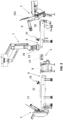
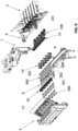
- machine 1 for forming paperboard trays comprises the following main elements:
- the magazine 2 contains a number of flat blanks 101 ( Fig. 2 ), each of which is arranged to be folded to form a tray.
- the extraction member 9 picks up a group of blanks and deposits them on the transfer plate 10.
- Said group of blanks is for example represented by a row 100 as shown in Fig. 9 .
- the transfer plate 10 preferably comprises retaining strikers arranged to hold the blanks in place once deposited on the plate itself.
- Glue sprayers 15 are placed along the path of the plate 10 and (as the plate 10 loaded with blanks passes by) dispense glue onto specific portions of the blanks to enable the tray walls to be closed, for example by gluing the tabs 106 ( Fig. 10 ) to the sides of the tray. Thanks to the glue applied by the sprayers 15, the tray will retain the three-dimensional shape imparted by coupling between the forming member 13 and the die 14.
- the member 11 picks up the frames from the magazine 3 and loads them onto the transfer plate 12, which carries the frames to the coupling station 6.
- the glue sprayers 16 apply an appropriate amount of glue to the frames which will be used for adhering the frames to the perimeter edges of the trays.
- the frames have, for example, the shape shown in Fig. 11 .
- pre-breaking operations may be carried out on the internal edges if necessary (to facilitate tray formation).
- the machine may be equipped with suitable devices for said edge pre-breaking operations in accordance with this requirement.
- the robot 7 carries a multi-head former 13 capable of simultaneously processing the row of blanks carried by the plate 12.
- the former 13 is associated with a robot end 70 (see also Fig. 6 ).
- Fig. 2 shows the robot 7 in a position suitable for picking up the blanks originating from the magazine 2 and conveyed by the plate 10.
- the robot is equipped with vacuum gripping members, such as suction cups or equivalent, which allow the blanks to be lifted from the plate 10.
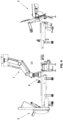
- Fig. 3 shows the robot 7 positioned in the tray forming station 5.
- a downwards movement of the former 13 in coupling with the die 14 imparts the desired tray shape to the blank, as will be illustrated in more detail below.
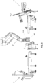
- the robot 7 moves to the station 6 ( Fig. 4 ). During this transfer (i.e. leaving the engagement with the die 14 and moving towards station 6) the gripping members of the robot 7 constantly maintain the vacuum which grips the trays in a relationship of engagement with the former 13 so as to maintain the correct centring.
- a row 200 of frames 201 (see Fig. 9 ) originating from the magazine 3 and already sprayed with glue as a result of the plate 12 passing under the sprayers 16 is arranged in station 6.
- the robot brings itself into alignment with the row of frames and with a downwards movement precisely fits the frames onto the trays. It should be noted that the frames do not leave the plate 12 and said plate 12 has appropriate through-windows to accommodate the forming member 13 until the edges of the trays are in contact with the frames.
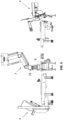
- Fig. 5 shows the machine in the set-up in which the assembled trays (i.e. complete with frame) are delivered to the output conveyor 8.
- output proceeds transversely of the machine, i.e. in a direction perpendicular to the drawing plane.
- vacuum gripping members are controlled to release the trays.
- a vacuum reversal system (known per se ) is provided to create a slight overpressure to facilitate separation of the trays from the former 13.
- Figs. 6 and 7 show further details of a preferred embodiment, with reference to robot 7 and die 14.
- the former 13 has a plurality of heads 130 and each of said heads 130 has an essentially truncated-pyramidal shape with side surfaces 131 inclined and converging downwards; the die 14 has a plurality of seats 140, each suitable for accommodating one of the heads 130; around the seats 140 there are a series of cams 142 provided with side surfaces 141 inclined and conjugate with the surfaces 131.
- the cams 142 can be adjustable to adapt the seat 140 to a format change and can be mobile (with controlled movement, coordinated with the descent of the former of the robot 13) to perform operations auxiliary to the composition of the tray.
- the blank is wrapped around the truncated-pyramidal head 130 to create the desired tray.
- the glue previously sprayed from the array of dispensers 15 grips and "closes" the tray by, for example, attaching the tabs 106 to the sides 104 ( Fig. 10 ).
- Fig. 8 shows a tray 102, shown with dotted line, which is in engagement with a head 130.
- the tray 102 is gripped by the described vacuum gripping members.
- Fig. 9 The operation of the machine in Fig. 1 is further illustrated in Fig. 9 .
- the extraction member 9 delivers a row 100 of flat blanks 101 to the transfer plate 10.
- the row 100 reaches the pick-up zone 4 (receiving the glue while passing under the array of sprayers 15) where it is taken over by the robot 7.
- the former 13 is not shown in Fig. 9 for simplicity.
- the extractor member 11 On the opposite side of the machine, the extractor member 11 generates a row 200 of frames 201.
- the frames 201 are correspondingly spaced apart from the blanks 101 to interface properly with the robot 7. In other words, the row 100 and the row 200 have the same spacing pitch. Note in station 6 the row 202 of frames already provided with glue ready for joining with the trays.
- the trays 102 remain in engagement with the forming device 13 in the manner illustrated in Fig. 8 .
- the robot 7 then moves to station 6 where the trays 102 are aligned with the underlying row 202 of frames (provided with glue) and by means of an essentially vertical downwards movement of the robot, the frames are fitted onto the trays until they are glued to the perimeter edge tabs.
- a set 300 of assembled trays 301 (complete with frame) is obtained and delivered to the output conveyor 8.
- the embodiment of the figures provides for the robot 7 to transfer the blanks from the transfer plate 10 ( Fig. 2 ) to the forming zone 5.
- the transfer plate 10 directly to reach the forming zone 5 by moving over the die 14.
- the robot 7 acts on the blanks while they are still loaded on the plate 10.
- the plate 10 has appropriate windows to allow the passage of the forming member 13 which will engage with the underlying die 14.
- FIGs. 10-13 show an example of a paperboard tray (or tub) which can be produced with the machine of the present invention.
- Fig. 10 shows an exemplary embodiment of a tray or tub 102 comprising a bottom 103, long side walls 104 and short side walls 105, and perimeter tabs 106, 107 extending outside the edges of the walls 104, 105.
- the short walls 105 have tabs 108 which fold down and become glued to the long walls 104.
- Fig. 10 shows the tray 102 in an inverted position, see also Fig. 13 .
- the bottom and side walls define a tub for containing a product, for example a food product.
- Fig. 11 shows a closed-loop frame 201 essentially formed of two long sides 205 and two short sides 206.
- the frame 201 comprises two tabs 202 extending from the short sides 206 towards the interior of the frame itself, intended to adhere to the short side walls 105 ( Fig. 12 ).
- tabs 202 have a trapezoidal shape.
- the frame 201 defines an opening 203 that allows the frame to be applied to the bottom 103 of the tray until the sides 205 and 206 are brought into line with the tabs 106, 107.
- Fig. 12 shows an assembled tray 301 (seen from below), obtainable by applying the frame 201 to the tray 102. Observing this figure, it is possible to note the positioning precision required by the coupling between the frame and the display, which is obtained thanks to the invention.
- Fig. 13 shows the tray 301 from above, it is possible to note the compartment 302 (for containing the product) which substantially follows the shape of the truncated pyramidal head 130.
- the corners of the tray 301 are formed correctly without coupling errors thanks to the underlying frame 201 which joins the perimeter edge tabs together and creates a uniform plane.
Landscapes
- Making Paper Articles (AREA)
Claims (16)
- Machine (1) pour la formation de plateaux en carton comprenant :un premier magasin (2) agencé pour recevoir des découpes plates (101) destinées à former des plateaux ; un deuxième magasin (3) agencé pour recevoir des cadres en carton en boucle fermée (201) applicables aux plateaux ;une station de mise en forme (5) de plateaux ;une station (6) pour coupler lesdits cadres auxdits plateaux ;un robot (7) apte à fonctionner entre lesdites stations de machine ;un système d'acheminement de découpes (9, 10) qui est agencé pour prélever les découpes à partir dudit premier magasin (2) et les distribuer audit robot (7) ou les transporter vers la station de mise en forme (5) ;un système d'acheminement de cadres (11, 12) agencé pour prélever les cadres à partir dudit deuxième magasin (3) et les transporter vers ladite station de couplage (6) ;dans laquelle :
le robot (7) transporte un élément de mise en forme (13) apte à mettre en forme au moins un plateau en carton à partir d'une découpe respective, coopérant avec une matrice (14) qui est située dans la station de mise en forme (5) et est apte à recevoir ledit élément de mise en forme (13) ;
et dans laquelle le robot (7) est configuré pour :réaliser dans ladite station de mise en forme (5) une opération de mise en forme en couplant ledit élément de mise en forme (13) à ladite matrice (14), ce qui permet d'obtenir un plateau en carton (102) qui est dans une relation de mise en prise avec l'élément de mise en forme (13) du robot, le plateau en carton obtenu présentant une cuve pour maintenir le produit délimité par un fond (103) et par des parois latérales (104, 105) et des languettes périmétriques (106, 107) s'étendant à partir des bords supérieurs desdites parois latérales ;positionner le plateau en carton dans la station de couplage (6) de manière à appliquer le cadre (201) sur les surfaces internes desdites languettes périmétriques orientées vers le fond du plateau ;dans laquelle le plateau reste dans une relation de mise en prise avec l'élément de mise en forme du robot, résultant du processus de mise en forme, pendant un transfert vers la station de couplage et pendant un couplage avec le cadre. - Machine selon la revendication 1, dans laquelle l'élément de mise en forme associé au robot présente un élément mâle (130) avec des premières surfaces inclinées (131) et la matrice présente un siège femelle (140) qui est apte à recevoir l'élément mâle du robot et présente des deuxièmes surfaces inclinées (141) conjuguées auxdites premières surfaces (131).
- Machine selon la revendication 2, dans laquelle la relation de mise en prise entre le plateau et l'élément de mise en forme du robot est créée par un élément de préhension à vide.
- Machine selon l'une quelconque des revendications précédentes, configurée pour traiter collectivement une pluralité de plateaux (100) et de cadres associés (200), ce qui permet d'obtenir une pluralité de plateaux assemblés dotés de cadres pour chaque cycle de production, dans laquelle :le système d'acheminement de découpes (9, 10) et le système d'acheminement de cadres (11, 12) sont configurés pour traiter un ensemble de découpes et un ensemble de cadres respectivement dans chaque cycle de production ;l'élément de mise en forme (13) du robot (7) présente une pluralité de têtes (130) et la matrice présente une pluralité de sièges (140), chaque tête coopérant avec un siège respectif pour former un plateau.
- Machine selon l'une quelconque des revendications précédentes dans laquelle le système d'acheminement de découpes comprend un élément transporteur (10) mobile entre une zone destinée à recevoir les découpes en provenance du magasin (2) et une zone (4) destinée à distribuer les découpes au robot.
- Machine selon l'une quelconque des revendications 1 à 4 dans laquelle le système d'acheminement de découpes comprend un élément transporteur (10) mobile entre une zone de réception pour des découpes en provenance du magasin et la station de mise en forme (5), dans laquelle l'élément transporteur (10), lorsqu'il est dans la station de mise en forme (5), est positionné au-dessus de la matrice (14).
- Machine selon l'une quelconque des revendications précédentes comprenant un réseau (15) de premiers distributeurs de colle agencé le long du trajet de l'élément transporteur (10) des découpes, lesdits distributeurs de colle étant configurés pour appliquer sélectivement de la colle sur des parties de la découpe destinées à être jointes ensemble dans l'étape de mise en forme de plateau.
- Machine selon l'une quelconque des revendications précédentes, dans laquelle les cadres sont appliqués aux languettes des plateaux par collage, et dans laquelle le système d'acheminement de cadres comprend un élément transporteur (12) mobile entre le deuxième magasin et la station de couplage, et la machine comprend un réseau (16) de deuxièmes distributeurs de colle agencé le long du trajet dudit élément transporteur, lesdits distributeurs de colle étant configurés pour appliquer une quantité appropriée de colle sur les cadres.
- Machine selon l'une quelconque des revendications précédentes, dans laquelle :la machine comprend un transporteur de sortie (8) pour plateaux assemblés et le robot (7) est configuré pour placer les plateaux assemblés, une fois que chaque plateau a été couplé avec son cadre, sur ledit transporteur de sortie, oule robot est configuré pour placer les plateaux assemblés directement sur une autre ligne de production ou machine.
- Machine selon l'une quelconque des revendications précédentes, dans laquelle la machine présente un agencement sensiblement longitudinal et dans laquelle, le long de l'étendue longitudinale de la machine :le premier magasin (2) et le deuxième magasin (3) sont situés à des extrémités opposées de la machine ;le transporteur de sortie (8) des plateaux assemblés est situé dans une position intermédiaire de la machine ;la station de mise en forme (5) de plateaux est située entre le premier magasin (2) et le transporteur de sortie (8) ;la station d'application de cadres (6) est située entre le deuxième magasin (3) et le transporteur de sortie (8).
- Procédé de fabrication d'un plateau en papier ou en carton dans une machine d'emballage, comprenant :la mise en forme d'un groupe de plateaux en carton à partir de découpes, par couplage d'un élément de mise en forme (13) associé à un robot (7) et à une matrice (14), résultant en ce que chaque découpe dans un plateau en carton (102) qui est dans une relation de mise en prise avec l'élément de mise en forme (13) du robot, le plateau en carton obtenu présentant un fond (103), des parois latérales (104, 105) et des languettes périmétriques (106, 107) s'étendant à partir desdites parois latérales ;l'agencement d'un groupe de cadres en carton en boucle fermée dans une station de couplage, les cadres étant égaux en nombre aux nombres de découpes, et étant agencés dans une configuration apte à ajuster sur les plateaux en carton en prise avec l'élément de mise en forme (13) du robot ;le déplacement du robot (7) dans la station de couplage (6) de manière à faire glisser les cadres (201) autour des plateaux jusqu'à ce que les cadres entrent en contact avec les languettes périmétriques, de manière à être joints aux languettes de préférence par collage ;dans lequel les plateaux en papier restent dans la relation de mise en prise avec l'appareil de mise en forme du robot, ce qui est obtenu par le processus de mise en forme, pendant un transfert vers la station de couplage et pendant un couplage avec les cadres.
- Procédé selon la revendication 11 dans lequel :
les découpes (101) sont acheminées à partir d'un magasin (2) de la machine et le procédé comprend :l'extraction des découpes à partir du magasin respectif (2) et le chargement desdites découpes sur un premier élément transporteur (10) ;le déplacement dudit premier élément transporteur (10) jusqu'à ce qu'il atteigne une zone (4) où les découpes sont distribuées au robot (7) ou directement à une zone de mise en forme ;l'application de colle sur les découpes au moyen de distributeurs de colle (15) agencés le long du trajet dudit premier élément transporteur, dans lequel la colle est appliquée à des parties de la découpe destinées à être jointes ensemble pendant la mise en forme du plateau ;et l'étape d'acheminement des cadres vers ladite station de couplage comprend en outre :l'extraction des cadres en provenance d'un magasin (3) et leur chargement sur un deuxième élément transporteur (12) ; le déplacement dudit deuxième élément transporteur en direction de ladite station de couplage (6) ;l'application de colle sur les cadres au moyen de deuxièmes distributeurs de colle (16) agencés le long du trajet dudit deuxième élément transporteur pour permettre un collage entre des cadres et des languettes de plateau. - Procédé selon la revendication 11 ou 12 dans lequel : un plateau en carton est mis en forme à partir d'une découpe par une coopération entre des premières surfaces inclinées d'un élément mâle de l'élément de mise en forme et des deuxièmes surfaces inclinées conjuguées aux premières surfaces inclinées et appartenant à un siège femelle de la matrice.
- Procédé selon l'une quelconque des revendications 11 à 13 dans lequel la relation de mise en prise entre les plateaux en carton et l'élément de mise en forme est maintenue par des éléments de préhension à vide associés à l'élément de mise en forme.
- Procédé selon l'une quelconque des revendications 11 à 14, dans lequel le plateau est mis en forme à partir de la découpe avec une course verticale de l'élément de mise en forme (13) à l'intérieur de la matrice (14) et un coulissement vertical de la découpe elle-même dans la matrice, avec un pliage et un collage de rabats externes de la découpe par une ou plusieurs cames disposées au niveau de la matrice.
- Procédé selon l'une quelconque des revendications 11 à 15, le procédé étant réalisé dans une machine selon l'une quelconque des revendications 1 à 10, et dans lequel le procédé est gouverné par un système de commande de machine.
Priority Applications (1)
| Application Number | Priority Date | Filing Date | Title |
|---|---|---|---|
| EP22168670.2A EP4261029B1 (fr) | 2022-04-15 | 2022-04-15 | Machine pour la fabrication d'un plateau en carton |
Applications Claiming Priority (1)
| Application Number | Priority Date | Filing Date | Title |
|---|---|---|---|
| EP22168670.2A EP4261029B1 (fr) | 2022-04-15 | 2022-04-15 | Machine pour la fabrication d'un plateau en carton |
Publications (3)
| Publication Number | Publication Date |
|---|---|
| EP4261029A1 EP4261029A1 (fr) | 2023-10-18 |
| EP4261029C0 EP4261029C0 (fr) | 2024-12-18 |
| EP4261029B1 true EP4261029B1 (fr) | 2024-12-18 |
Family
ID=81877732
Family Applications (1)
| Application Number | Title | Priority Date | Filing Date |
|---|---|---|---|
| EP22168670.2A Active EP4261029B1 (fr) | 2022-04-15 | 2022-04-15 | Machine pour la fabrication d'un plateau en carton |
Country Status (1)
| Country | Link |
|---|---|
| EP (1) | EP4261029B1 (fr) |
Family Cites Families (5)
| Publication number | Priority date | Publication date | Assignee | Title |
|---|---|---|---|---|
| FR2480708A1 (fr) * | 1980-11-07 | 1981-10-23 | Impression Cartonnage Ste Pari | Contenant en carton plie revetu d'une pellicule en matiere synthetique et muni d'un cadre peripherique en une seule piece ainsi que son procede de fabrication |
| DE19828381A1 (de) * | 1998-06-25 | 1999-12-30 | Jochen Dietrich | Lebensmittelverpackung sowie Verfahren, Zuschnitt und Vorrichtung zu deren Herstellung |
| JP5258276B2 (ja) * | 2007-12-11 | 2013-08-07 | 森永製菓株式会社 | トレーの成形供給方法及びトレーの成形供給装置 |
| ITRE20100016A1 (it) * | 2010-03-05 | 2011-09-06 | All Glass S R L | Apparecchiatura e metodo per la formazione di vassoi bordati |
| JP6151322B2 (ja) * | 2015-09-09 | 2017-06-21 | 大森機械工業株式会社 | 製函装置 |
-
2022
- 2022-04-15 EP EP22168670.2A patent/EP4261029B1/fr active Active
Also Published As
| Publication number | Publication date |
|---|---|
| EP4261029C0 (fr) | 2024-12-18 |
| EP4261029A1 (fr) | 2023-10-18 |
Similar Documents
| Publication | Publication Date | Title |
|---|---|---|
| CN108544795B (zh) | 一种纸盒的制盒设备及其制盒方法 | |
| US12384579B2 (en) | System and process for forming retained container groups from arrayed container groups | |
| US9145222B2 (en) | Folding method and apparatus for making a carton | |
| EP1371564B1 (fr) | Procédé et dispositif pour emballer un produit utilisant un emballage tubulaire plat | |
| US8387349B2 (en) | Machine for cartoning products | |
| US10507944B2 (en) | Machine and method for folding and adhesively bonding blanks for the production of folding boxes | |
| US20100210440A1 (en) | Machine for shaping blanks of cardboard boxes | |
| US20070204567A1 (en) | Top load cartoner | |
| JP4913009B2 (ja) | 製函包装装置 | |
| KR100447516B1 (ko) | 박스의 조립장치 | |
| US7331915B2 (en) | Assembly device of plate elements for a processing machine | |
| CN112356497A (zh) | 一种全自动纸质包装盒成型设备及方法 | |
| US7607282B2 (en) | Machine for automated packaging of products(s) in a cardboard box | |
| JP2019089333A (ja) | 被覆段ボール箱の製造ライン | |
| EP1357038A1 (fr) | Procédé et appareil de préhension et de mise en forme de flans en carton découpés pour la formation de boítes d'emballage ouvertes vers le haut | |
| EP4261029B1 (fr) | Machine pour la fabrication d'un plateau en carton | |
| US11198268B2 (en) | Device and method for removing a box from a chuck | |
| CN211917839U (zh) | 多工位纸盒成型机 | |
| CN214027437U (zh) | 一种纸质包装盒用围条的成型器 | |
| CN114536864A (zh) | 一种全自动折叠盒组装成型机及成型方法 | |
| CN112223829B (zh) | 一种包装盒成型除泡设备 | |
| CN214821221U (zh) | 一种用于围条和盒盖的连接部件 | |
| CN214354476U (zh) | 一种用于盒体和盒盖的连接部件 | |
| CN214354475U (zh) | 一种纸质包装盒盒体的流转设备 | |
| US20230241856A1 (en) | System for destacking carton blanks |
Legal Events
| Date | Code | Title | Description |
|---|---|---|---|
| PUAI | Public reference made under article 153(3) epc to a published international application that has entered the european phase |
Free format text: ORIGINAL CODE: 0009012 |
|
| STAA | Information on the status of an ep patent application or granted ep patent |
Free format text: STATUS: THE APPLICATION HAS BEEN PUBLISHED |
|
| AK | Designated contracting states |
Kind code of ref document: A1 Designated state(s): AL AT BE BG CH CY CZ DE DK EE ES FI FR GB GR HR HU IE IS IT LI LT LU LV MC MK MT NL NO PL PT RO RS SE SI SK SM TR |
|
| STAA | Information on the status of an ep patent application or granted ep patent |
Free format text: STATUS: REQUEST FOR EXAMINATION WAS MADE |
|
| 17P | Request for examination filed |
Effective date: 20240405 |
|
| RBV | Designated contracting states (corrected) |
Designated state(s): AL AT BE BG CH CY CZ DE DK EE ES FI FR GB GR HR HU IE IS IT LI LT LU LV MC MK MT NL NO PL PT RO RS SE SI SK SM TR |
|
| GRAP | Despatch of communication of intention to grant a patent |
Free format text: ORIGINAL CODE: EPIDOSNIGR1 |
|
| STAA | Information on the status of an ep patent application or granted ep patent |
Free format text: STATUS: GRANT OF PATENT IS INTENDED |
|
| RIC1 | Information provided on ipc code assigned before grant |
Ipc: B31B 120/00 20170101ALN20240730BHEP Ipc: B31B 120/50 20170101ALN20240730BHEP Ipc: B31B 110/35 20170101ALN20240730BHEP Ipc: B31B 110/10 20170101ALN20240730BHEP Ipc: B31B 105/00 20170101ALN20240730BHEP Ipc: B31B 50/62 20170101ALI20240730BHEP Ipc: B31B 50/44 20170101ALI20240730BHEP Ipc: B31B 50/04 20170101AFI20240730BHEP |
|
| INTG | Intention to grant announced |
Effective date: 20240808 |
|
| GRAS | Grant fee paid |
Free format text: ORIGINAL CODE: EPIDOSNIGR3 |
|
| GRAA | (expected) grant |
Free format text: ORIGINAL CODE: 0009210 |
|
| STAA | Information on the status of an ep patent application or granted ep patent |
Free format text: STATUS: THE PATENT HAS BEEN GRANTED |
|
| AK | Designated contracting states |
Kind code of ref document: B1 Designated state(s): AL AT BE BG CH CY CZ DE DK EE ES FI FR GB GR HR HU IE IS IT LI LT LU LV MC MK MT NL NO PL PT RO RS SE SI SK SM TR |
|
| REG | Reference to a national code |
Ref country code: CH Ref legal event code: EP |
|
| REG | Reference to a national code |
Ref country code: DE Ref legal event code: R096 Ref document number: 602022008729 Country of ref document: DE |
|
| REG | Reference to a national code |
Ref country code: IE Ref legal event code: FG4D |
|
| U01 | Request for unitary effect filed |
Effective date: 20250114 |
|
| U07 | Unitary effect registered |
Designated state(s): AT BE BG DE DK EE FI FR IT LT LU LV MT NL PT RO SE SI Effective date: 20250120 |
|
| PG25 | Lapsed in a contracting state [announced via postgrant information from national office to epo] |
Ref country code: HR Free format text: LAPSE BECAUSE OF FAILURE TO SUBMIT A TRANSLATION OF THE DESCRIPTION OR TO PAY THE FEE WITHIN THE PRESCRIBED TIME-LIMIT Effective date: 20241218 |
|
| PG25 | Lapsed in a contracting state [announced via postgrant information from national office to epo] |
Ref country code: NO Free format text: LAPSE BECAUSE OF FAILURE TO SUBMIT A TRANSLATION OF THE DESCRIPTION OR TO PAY THE FEE WITHIN THE PRESCRIBED TIME-LIMIT Effective date: 20250318 |
|
| U20 | Renewal fee for the european patent with unitary effect paid |
Year of fee payment: 4 Effective date: 20250319 |
|
| PG25 | Lapsed in a contracting state [announced via postgrant information from national office to epo] |
Ref country code: GR Free format text: LAPSE BECAUSE OF FAILURE TO SUBMIT A TRANSLATION OF THE DESCRIPTION OR TO PAY THE FEE WITHIN THE PRESCRIBED TIME-LIMIT Effective date: 20250319 |
|
| PG25 | Lapsed in a contracting state [announced via postgrant information from national office to epo] |
Ref country code: RS Free format text: LAPSE BECAUSE OF FAILURE TO SUBMIT A TRANSLATION OF THE DESCRIPTION OR TO PAY THE FEE WITHIN THE PRESCRIBED TIME-LIMIT Effective date: 20250318 |
|
| PG25 | Lapsed in a contracting state [announced via postgrant information from national office to epo] |
Ref country code: SM Free format text: LAPSE BECAUSE OF FAILURE TO SUBMIT A TRANSLATION OF THE DESCRIPTION OR TO PAY THE FEE WITHIN THE PRESCRIBED TIME-LIMIT Effective date: 20241218 |
|
| PG25 | Lapsed in a contracting state [announced via postgrant information from national office to epo] |
Ref country code: PL Free format text: LAPSE BECAUSE OF FAILURE TO SUBMIT A TRANSLATION OF THE DESCRIPTION OR TO PAY THE FEE WITHIN THE PRESCRIBED TIME-LIMIT Effective date: 20241218 |
|
| PG25 | Lapsed in a contracting state [announced via postgrant information from national office to epo] |
Ref country code: ES Free format text: LAPSE BECAUSE OF FAILURE TO SUBMIT A TRANSLATION OF THE DESCRIPTION OR TO PAY THE FEE WITHIN THE PRESCRIBED TIME-LIMIT Effective date: 20241218 |
|
| PG25 | Lapsed in a contracting state [announced via postgrant information from national office to epo] |
Ref country code: IS Free format text: LAPSE BECAUSE OF FAILURE TO SUBMIT A TRANSLATION OF THE DESCRIPTION OR TO PAY THE FEE WITHIN THE PRESCRIBED TIME-LIMIT Effective date: 20250418 |
|
| PG25 | Lapsed in a contracting state [announced via postgrant information from national office to epo] |
Ref country code: SK Free format text: LAPSE BECAUSE OF FAILURE TO SUBMIT A TRANSLATION OF THE DESCRIPTION OR TO PAY THE FEE WITHIN THE PRESCRIBED TIME-LIMIT Effective date: 20241218 |
|
| PG25 | Lapsed in a contracting state [announced via postgrant information from national office to epo] |
Ref country code: CZ Free format text: LAPSE BECAUSE OF FAILURE TO SUBMIT A TRANSLATION OF THE DESCRIPTION OR TO PAY THE FEE WITHIN THE PRESCRIBED TIME-LIMIT Effective date: 20241218 |
|
| PLBE | No opposition filed within time limit |
Free format text: ORIGINAL CODE: 0009261 |
|
| STAA | Information on the status of an ep patent application or granted ep patent |
Free format text: STATUS: NO OPPOSITION FILED WITHIN TIME LIMIT |
|
| REG | Reference to a national code |
Ref country code: CH Ref legal event code: L10 Free format text: ST27 STATUS EVENT CODE: U-0-0-L10-L00 (AS PROVIDED BY THE NATIONAL OFFICE) Effective date: 20251029 |
|
| REG | Reference to a national code |
Ref country code: CH Ref legal event code: H13 Free format text: ST27 STATUS EVENT CODE: U-0-0-H10-H13 (AS PROVIDED BY THE NATIONAL OFFICE) Effective date: 20251125 |
|
| 26N | No opposition filed |
Effective date: 20250919 |
|
| PG25 | Lapsed in a contracting state [announced via postgrant information from national office to epo] |
Ref country code: MC Free format text: LAPSE BECAUSE OF FAILURE TO SUBMIT A TRANSLATION OF THE DESCRIPTION OR TO PAY THE FEE WITHIN THE PRESCRIBED TIME-LIMIT Effective date: 20241218 |
|
| PG25 | Lapsed in a contracting state [announced via postgrant information from national office to epo] |
Ref country code: CH Free format text: LAPSE BECAUSE OF NON-PAYMENT OF DUE FEES Effective date: 20250430 |
|
| PG25 | Lapsed in a contracting state [announced via postgrant information from national office to epo] |
Ref country code: IE Free format text: LAPSE BECAUSE OF NON-PAYMENT OF DUE FEES Effective date: 20250415 |