EP4261066B1 - Système d'alimentation en air pour véhicules à moteur et véhicule à moteur, en particulier un camion, comprenant un tel système d'alimentation en air - Google Patents
Système d'alimentation en air pour véhicules à moteur et véhicule à moteur, en particulier un camion, comprenant un tel système d'alimentation en air Download PDFInfo
- Publication number
- EP4261066B1 EP4261066B1 EP22168249.5A EP22168249A EP4261066B1 EP 4261066 B1 EP4261066 B1 EP 4261066B1 EP 22168249 A EP22168249 A EP 22168249A EP 4261066 B1 EP4261066 B1 EP 4261066B1
- Authority
- EP
- European Patent Office
- Prior art keywords
- air guide
- air
- supplying system
- air supplying
- guide
- Prior art date
- Legal status (The legal status is an assumption and is not a legal conclusion. Google has not performed a legal analysis and makes no representation as to the accuracy of the status listed.)
- Active
Links
Images




Classifications
-
- B—PERFORMING OPERATIONS; TRANSPORTING
- B60—VEHICLES IN GENERAL
- B60K—ARRANGEMENT OR MOUNTING OF PROPULSION UNITS OR OF TRANSMISSIONS IN VEHICLES; ARRANGEMENT OR MOUNTING OF PLURAL DIVERSE PRIME-MOVERS IN VEHICLES; AUXILIARY DRIVES FOR VEHICLES; INSTRUMENTATION OR DASHBOARDS FOR VEHICLES; ARRANGEMENTS IN CONNECTION WITH COOLING, AIR INTAKE, GAS EXHAUST OR FUEL SUPPLY OF PROPULSION UNITS IN VEHICLES
- B60K11/00—Arrangement in connection with cooling of propulsion units
- B60K11/02—Arrangement in connection with cooling of propulsion units with liquid cooling
- B60K11/04—Arrangement or mounting of radiators, radiator shutters, or radiator blinds
-
- B—PERFORMING OPERATIONS; TRANSPORTING
- B60—VEHICLES IN GENERAL
- B60K—ARRANGEMENT OR MOUNTING OF PROPULSION UNITS OR OF TRANSMISSIONS IN VEHICLES; ARRANGEMENT OR MOUNTING OF PLURAL DIVERSE PRIME-MOVERS IN VEHICLES; AUXILIARY DRIVES FOR VEHICLES; INSTRUMENTATION OR DASHBOARDS FOR VEHICLES; ARRANGEMENTS IN CONNECTION WITH COOLING, AIR INTAKE, GAS EXHAUST OR FUEL SUPPLY OF PROPULSION UNITS IN VEHICLES
- B60K11/00—Arrangement in connection with cooling of propulsion units
- B60K11/08—Air inlets for cooling; Shutters or blinds therefor
-
- B—PERFORMING OPERATIONS; TRANSPORTING
- B60—VEHICLES IN GENERAL
- B60Y—INDEXING SCHEME RELATING TO ASPECTS CROSS-CUTTING VEHICLE TECHNOLOGY
- B60Y2200/00—Type of vehicle
- B60Y2200/10—Road Vehicles
- B60Y2200/14—Trucks; Load vehicles, Busses
-
- B—PERFORMING OPERATIONS; TRANSPORTING
- B60—VEHICLES IN GENERAL
- B60Y—INDEXING SCHEME RELATING TO ASPECTS CROSS-CUTTING VEHICLE TECHNOLOGY
- B60Y2410/00—Constructional features of vehicle sub-units
- B60Y2410/10—Housings
Definitions
- the present invention concerns an air supplying system for motor vehicles, and to a motor vehicle, in particular a truck, comprising such an air supplying system.
- the air supplying system according to the present invention is particularly suitable for being used in trucks or similar type of vehicles and will be described hereinafter by making specific reference to such application, without intending in any way to limit its possible use in other types of motor vehicles.
- motor vehicles use air supplying systems in order to provide flows of fresh air suitable for cooling the engine of the motor vehicles.
- air supplying systems are disclosed in documents DE 10 2020 114756 A1 , US 2021/129915 A1 , US 3 165 164 A and US 2 912 057 A .
- some known trucks use air supplying systems which are associated to and are configured for conveying air flows to the front radiator of a truck.
- An air gap is formed between the upper air guide and the lower air guide, which may lead to some air escapes; in turn, these air escapes generate undesired turbulences, increase the drag force required to the vehicle, worsen the cooling capabilities, and in the end negatively impact the overall efficiency of the vehicles in terms of fuel consumption.
- the main aim of the present invention is to provide a solution able to mitigate, at least partially, one or more of the above mentioned issues.
- an air supplying system for a motor vehicle comprising:
- the air supplying system for a motor vehicle according to the invention may comprise one or more of the following features, which may be combined in any technical feasible combination
- the main aim of the present invention is also achieved by a motor vehicle and by a truck comprising each an air supplying system as above indicated, and in particular as described in more details hereinafter and defined in the appended claims.
- any component as a whole, or to any part of a component, or to a combination of components, it has to be understood that it means and encompasses correspondingly either the structure, and/or configuration and/or form and/or positioning of the related component or part thereof, or combinations, such term refers to.
- Figure 1 schematically illustrates an air supplying system 100 for a motor vehicle, such as for instance a truck.
- a truck in the form of a semi-trailer tractor is illustrated in figure 5 and therein indicated with the reference number 1.
- such truck 1 comprises for example a chassis 2, a cabin 3, and a radiator 4 which is installed at the front of the truck 1.
- the air supplying system 100 comprises an upper air guide 10 and at least a lower and/or a side air guide 20 which are adapted to be installed on board of the truck 1, for example around the radiator 4 (schematically represented in figure 1 ) and are suitable for providing flows of cooling air, e.g. to be conveyed towards the radiator 4 itself for improving in the end cooling of the engine of the truck 1.
- the upper air guide 10 may move relative to the first lower or side air guide 20 or vice versa.
- the upper air guide 10 which can be installed for instance on and solidly movable with the cabin 3, comprises for instance a central portion 11, positioned above the radiator 4, a first side portion 12 and a further side portion 13 which protrude downwardly from the ends of the central portion 11 towards the and at the sides of the radiator 4.
- the at least a lower and/or a side air guide 20 comprises a first lower air guide 20 which can be fixed to the chassis 2 under the upper air guide 20, for example on a side of the radiator 4, and comprises an own portion 22.
- the upper air guide 10 and the first lower air guide 20 are mutually positioned with the respective first side portion 12 and own portion 22 which face to each other with a first air gap 15 defined there between.
- the air supplying system 100 can comprise also a second lower or side air guide 220, substantially identical or very similar to the first lower air guide 20, which is also fixed for instance to the chassis 2 under the upper air guide 20, for example at the opposite side of the radiator 4, and comprises an own portion 222; likewise, the upper air guide 10 and the second lower air guide 220 are mutually positioned with the respective further side portion 13 and own portion 222 which face to each other with a second air gap 215 defined there between.
- the air supplying system 100 comprises at least a first device 30 which is positioned, at least in part, between the first portion 12 of the upper air guide 10 and the own portion 22 (hereinafter referred to as the second portion 22), and is configured to substantially close the first air gap 15.
- the first device 30 includes at least one deformable portion which is arranged to allow the first device 30 itself to deform upon a relative movement between the upper air guide 10 and the first lower air guide 20 while keeping the first air gap 15 substantially closed.
- the first device 30 is configured to close the first air gap 15 in a substantially airtight manner, i.e. to substantially prevent air escapes at the first air gap 15.
- the upper air guide 10 and the first lower air guide 20 are adapted to be installed on board of the truck 1 with the respective first portion 12 and second portion 22 substantially aligned to each other in a virtual vertical plan (coinciding with the sheet on which figure 1 is depicted), and the at least one deformable portion is arranged to allow the first device 30 to deform displacing along a substantially vertical axis Z lying on or parallel to the virtual vertical plan.
- the first device 30 is connected, for instance mechanically, to the first lower air guide 20.
- the first device 30 comprises or is constituted by at least a first bellow forming or incorporating in its body said at least one deformable portion, which can be made for instance of rubber.
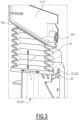
- FIG. 2 An exemplary embodiment of such first deformable bellow is illustrated in figure 2 and its operative coupling with the first portion 12 and the second portion 22 is illustrated in more details in figure 3 .
- the first bellow comprises a base portion 32 which is adapted to be connected to the second portion 22 of the first lower air guide 20, an upper portion 33 suitable to be operatively connected to an associated surface 12A of the first portion 12 of the upper air guide 10, and an intermediate portion 34 which extends between the base portion 32 and the upper portion 33 and is suitable to be positioned at and close the first air gap 15.
- the first bellow comprises corrugated side walls which favoring its deformation.
- the upper portion 34 comprises an inclined top surface 33A.
- the upper portion 33 via the top inclined surface 33A, offers a bearing surface on which the surface 12A of the first portion can rest against.
- the upper portion 33 can be coupled with the first portion 12 of the upper air guide 10, for example by means of one or more transverse ribs of the first portion 12 entering in corresponding recesses formed by adjacent corrugations of the corrugated side walls.
- the air supplying system 100 further comprises a mounting base 40, illustrated in figure 4 , which is arranged to be connected at a base portion 32 of the first bellow and to be releasably fastened to the second portion 22 of the first lower air guide 20, e.g. screwed, as illustrated in figure 3 .
- the mounting base 40 comprises a central opening 41 suitable for allowing flows of air moving into and out from the inside of the first bellow.
- the mounting base 40 comprises a rim 42 defined around the border of the opening 41, which protrudes upwardly and is suitable to be coupled with the base portion 32 of the first bellow.
- the mounting base 40 is made of plastic.
- a second device 30, substantially identical to the first device 30, can be installed to substantially close the second gap 215 as well, with its at least one deformable portion arranged to allow the second device 30 itself to deform upon a relative movement between the upper air guide 10 and the second lower air guide 20, while keeping the second air gap 215 substantially closed.
- the second device 30 can comprise or be constituted by a further bellow, substantially identical to the first bellow previously described, and a further mounting base 40 can be likewise used.
- the air supplying system 100 allows achieving the intended aim and is capable of at least reducing air escapes and thus turbulences. In this way, the aerodynamic behavior is ameliorated, and the cooling efficacy and the fuel consumption efficiency of a motor vehicle are improved.
- the use of the described first device 30 allows to properly and substantially close an air gap present between the upper and lower guides.
- the solution hereby conceived forms a kind of aerodynamic seal which properly works not only in static conditions but also dynamically, e.g. when for example the upper air guide 10 moves relative to the lower air guide 20 (and/or 220), e.g. along the vertical axis Z.
- the capability of deformation of the device(s) 30 allows to "absorb" such a relative movement.
- each device 30 used can take up the load exerted acting as a dynamic damper with the air flows moving as for example illustrated by the arrows F in figure 3 .
- the air supplying system 100 thus conceived is susceptible of modifications and variations, all of which are within the scope of the appended claims.
- some of the components can be positioned or shaped differently with respect to what previously described, provided that they remain suitable for the scope and tasks devised for them within the frame of the present invention; for instance, one or more of the air guides 10, 20 and 220 may be formed by a single piece, or by multiple pieces.
Landscapes
- Engineering & Computer Science (AREA)
- Chemical & Material Sciences (AREA)
- Combustion & Propulsion (AREA)
- Transportation (AREA)
- Mechanical Engineering (AREA)
- Cooling, Air Intake And Gas Exhaust, And Fuel Tank Arrangements In Propulsion Units (AREA)
Claims (15)
- Système d'alimentation en air (100) pour un véhicule à moteur, comprenant :- un guide d'air supérieur (10) et au moins un premier guide d'air inférieur (20) qui sont adaptés pour être installés à bord du véhicule à moteur et fournir des flux d'air de refroidissement, dans lequel ledit guide d'air supérieur (10) et ledit premier guide d'air inférieur (20) comprennent une première partie (12) et une seconde partie (22), respectivement, qui sont agencées en face l'une de l'autre avec un premier espace d'air (15) défini entre elles ;caractérisé en ce qu'il comprend en outre au moins un premier dispositif (30) qui est positionné, au moins en partie, entre ladite première partie (12) du guide d'air supérieur (10) et ladite seconde partie (22) du premier guide d'air (10) et est configuré pour fermer sensiblement ledit premier espace d'air (15), dans lequel le premier dispositif (30) comprend au moins une partie déformable qui est agencée pour permettre au premier dispositif (30) de se déformer lors d'un mouvement relatif entre ledit guide d'air supérieur (10) et ledit premier guide d'air inférieur (20) tout en gardant le premier espace d'air (15) sensiblement fermé.
- Système d'alimentation en air (100) selon la revendication 1, dans lequel ledit premier dispositif (30) est configuré pour fermer ledit premier espace d'air (15) d'une manière sensiblement étanche à l'air.
- Système d'alimentation en air (100) selon la revendication 1 ou 2, dans lequel ledit guide d'air supérieur (10) et ledit premier guide d'air inférieur (20) sont adaptés pour être installés à bord du véhicule à moteur avec ladite première partie (12) et ladite seconde partie (22) sensiblement alignées l'une par rapport à l'autre dans un plan vertical virtuel, et dans lequel ladite au moins une partie déformable est agencée pour permettre au premier dispositif (30) de se déformer en se déplaçant le long d'un axe sensiblement vertical (Z) situé sur ledit plan vertical virtuel ou parallèle à celui-ci.
- Système d'alimentation en air (100) selon une ou plusieurs des revendications précédentes, dans lequel ledit premier dispositif (30) est relié mécaniquement à au moins l'un dudit guide d'air supérieur (10) et du premier guide d'air inférieur (20).
- Système d'alimentation en air (100) selon une ou plusieurs des revendications précédentes, dans lequel ledit premier dispositif (30) comprend ou est constitué par au moins un premier soufflet formant ou intégrant dans son corps ladite au moins une portion déformable.
- Système d'alimentation en air (100) selon la revendication 5, dans lequel ledit au moins un premier soufflet comprend une partie de base (32) adaptée pour être reliée à ladite seconde partie (22) du premier guide d'air inférieur (20), une partie supérieure (33) adaptée pour être couplée de manière opérationnelle à une surface associée (12A) de la première partie (12) du guide d'air supérieur (10), et une partie intermédiaire (34) qui s'étend entre la partie de base (32) et la partie supérieure (33) et est adaptée pour être positionnée au niveau du premier espace d'air (15) et pour le fermer.
- Système d'alimentation en air (100) selon la revendication 6, dans lequel ladite partie supérieure (34) comprend une surface supérieure inclinée (33A).
- Système d'alimentation en air (100) selon une ou plusieurs des revendications 5 à 7, dans lequel ledit
au moins un premier soufflet comprend des parois latérales ondulées (33B). - Système d'alimentation en air (100) selon une ou plusieurs des revendications 5 à 8, dans lequel ledit au moins un premier soufflet est en caoutchouc.
- Système d'alimentation en air (100) selon une ou plusieurs des revendications 5 à 9, dans lequel il comprend en outre une base de montage (40) qui est agencée pour être connectée à une partie de base (32) du premier soufflet et pour être fixée de manière amovible à la seconde partie (22) du premier guide d'air inférieur (20).
- Système d'alimentation en air (100) selon la revendication 10, dans lequel ladite base de montage (40) comprend une ouverture centrale (41) adaptée pour permettre à des flux d'air d'entrer à l'intérieur du premier soufflet et d'en sortir.
- Système d'alimentation en air (100) selon la revendication 9 ou 10, dans lequel ladite base de montage (40) est en plastique.
- Système d'alimentation en air (100) selon une ou plusieurs des revendications précédentes, dans lequel le guide d'air supérieur (10) comprend une autre partie latérale (13) et le système d'alimentation en air (100) comprend en outre un second guide d'air inférieur (220) ayant une partie propre (222), ledit guide d'air supérieur (10) et ledit second guide d'air inférieur (20) étant mutuellement agencés avec ladite autre partie latérale (13) et ladite partie propre (222) se faisant face l'une à l'autre avec un second espace d'air (215) défini entre elles, et dans lequel le système d'alimentation en air (100) comprend en outre un second dispositif (30) qui est positionné, au moins en partie, entre ladite autre partie (13) du guide d'air supérieur (10) et ladite partie propre (222) du second guide d'air inférieur (220) et est configuré pour fermer sensiblement ledit premier second espace d'air (215), le second dispositif (30) comprenant au moins une partie déformable qui est agencée pour permettre au second dispositif (30) de se déformer, lors d'un mouvement relatif entre ledit guide d'air supérieur (10) et ledit second guide d'air inférieur (20), tout en gardant le second espace d'air (215) sensiblement fermé.
- Véhicule à moteur comprenant un système d'alimentationen air (100) selon une ou plusieurs desrevendications précédentes.
- Camion comprenant un système d'alimentation
en air (100) selon une ou plusieurs des revendications 1 à 13.
Priority Applications (2)
| Application Number | Priority Date | Filing Date | Title |
|---|---|---|---|
| EP22168249.5A EP4261066B1 (fr) | 2022-04-13 | 2022-04-13 | Système d'alimentation en air pour véhicules à moteur et véhicule à moteur, en particulier un camion, comprenant un tel système d'alimentation en air |
| US18/296,152 US20230331078A1 (en) | 2022-04-13 | 2023-04-05 | Air supplying system for motor vehicles, and motor vehicle, in particular a truck, comprising such air supplying system |
Applications Claiming Priority (1)
| Application Number | Priority Date | Filing Date | Title |
|---|---|---|---|
| EP22168249.5A EP4261066B1 (fr) | 2022-04-13 | 2022-04-13 | Système d'alimentation en air pour véhicules à moteur et véhicule à moteur, en particulier un camion, comprenant un tel système d'alimentation en air |
Publications (3)
| Publication Number | Publication Date |
|---|---|
| EP4261066A1 EP4261066A1 (fr) | 2023-10-18 |
| EP4261066B1 true EP4261066B1 (fr) | 2024-09-25 |
| EP4261066C0 EP4261066C0 (fr) | 2024-09-25 |
Family
ID=81308453
Family Applications (1)
| Application Number | Title | Priority Date | Filing Date |
|---|---|---|---|
| EP22168249.5A Active EP4261066B1 (fr) | 2022-04-13 | 2022-04-13 | Système d'alimentation en air pour véhicules à moteur et véhicule à moteur, en particulier un camion, comprenant un tel système d'alimentation en air |
Country Status (2)
| Country | Link |
|---|---|
| US (1) | US20230331078A1 (fr) |
| EP (1) | EP4261066B1 (fr) |
Family Cites Families (4)
| Publication number | Priority date | Publication date | Assignee | Title |
|---|---|---|---|---|
| US2912057A (en) * | 1958-03-14 | 1959-11-10 | Int Harvester Co | Motor vehicle tiltable cab and radiator construction |
| US3165164A (en) * | 1961-12-07 | 1965-01-12 | Int Harvester Co | Motor vehicle radiator mounting means |
| US11414134B2 (en) * | 2019-10-14 | 2022-08-16 | Mercedes-Benz Group AG | Electric drive supporting component platform for semi-tractor and truck vehicles |
| DE102020114756A1 (de) * | 2020-06-03 | 2021-12-09 | Man Truck & Bus Se | Vorbaustruktur für ein Nutzfahrzeug, vorzugsweise für einen Lastkraftwagen |
-
2022
- 2022-04-13 EP EP22168249.5A patent/EP4261066B1/fr active Active
-
2023
- 2023-04-05 US US18/296,152 patent/US20230331078A1/en active Pending
Also Published As
| Publication number | Publication date |
|---|---|
| EP4261066A1 (fr) | 2023-10-18 |
| US20230331078A1 (en) | 2023-10-19 |
| EP4261066C0 (fr) | 2024-09-25 |
Similar Documents
| Publication | Publication Date | Title |
|---|---|---|
| US10981424B2 (en) | Suspension control arm with integrated resilient element | |
| CN109795316B (zh) | 用于变速器安装架的止动件 | |
| US10800244B2 (en) | Motor vehicle battery arranged on a rear floor | |
| JPH0584246B2 (fr) | ||
| JP2008543665A (ja) | フレーム状構造を備える組立て支持体 | |
| CN101665100B (zh) | 汽车abs安装支架 | |
| US20120248823A1 (en) | Bulkhead structure | |
| KR20030048096A (ko) | 차량, 특히 자동차용 연료 셀 유닛 | |
| EP4261066B1 (fr) | Système d'alimentation en air pour véhicules à moteur et véhicule à moteur, en particulier un camion, comprenant un tel système d'alimentation en air | |
| CN202788369U (zh) | 一种压溃式发动机盖铰链 | |
| US20200148147A1 (en) | Grille shutter | |
| CN103921752A (zh) | 一种设有安全气囊模块定位装置的方向盘 | |
| US11970219B2 (en) | Trim assembly for a vehicle | |
| US9327573B2 (en) | Air spring attachment system | |
| CN218906827U (zh) | 空气悬架和具有其的车辆 | |
| CN202294264U (zh) | 变速器悬置限位机构 | |
| CN101333982A (zh) | 汽车空滤器支架 | |
| EP3792163B1 (fr) | Diffuseur actif tournant pour véhicule | |
| CN221873985U (zh) | 一种安装支架及车辆 | |
| CN202294627U (zh) | 车辆用保险杠构造 | |
| CN209634571U (zh) | 汽车车架的悬臂式安装支架 | |
| CN216916010U (zh) | 车辆的纵梁组件以及车辆 | |
| US20250026407A1 (en) | Protective structure | |
| CN218769939U (zh) | 一种新能源汽车蓄电池固定装置 | |
| CN221163045U (zh) | 一种闭式空气供给系统连接板 |
Legal Events
| Date | Code | Title | Description |
|---|---|---|---|
| PUAI | Public reference made under article 153(3) epc to a published international application that has entered the european phase |
Free format text: ORIGINAL CODE: 0009012 |
|
| STAA | Information on the status of an ep patent application or granted ep patent |
Free format text: STATUS: THE APPLICATION HAS BEEN PUBLISHED |
|
| AK | Designated contracting states |
Kind code of ref document: A1 Designated state(s): AL AT BE BG CH CY CZ DE DK EE ES FI FR GB GR HR HU IE IS IT LI LT LU LV MC MK MT NL NO PL PT RO RS SE SI SK SM TR |
|
| STAA | Information on the status of an ep patent application or granted ep patent |
Free format text: STATUS: REQUEST FOR EXAMINATION WAS MADE |
|
| 17P | Request for examination filed |
Effective date: 20240320 |
|
| RBV | Designated contracting states (corrected) |
Designated state(s): AL AT BE BG CH CY CZ DE DK EE ES FI FR GB GR HR HU IE IS IT LI LT LU LV MC MK MT NL NO PL PT RO RS SE SI SK SM TR |
|
| RIC1 | Information provided on ipc code assigned before grant |
Ipc: B60K 11/04 20060101AFI20240426BHEP |
|
| GRAJ | Information related to disapproval of communication of intention to grant by the applicant or resumption of examination proceedings by the epo deleted |
Free format text: ORIGINAL CODE: EPIDOSDIGR1 |
|
| STAA | Information on the status of an ep patent application or granted ep patent |
Free format text: STATUS: GRANT OF PATENT IS INTENDED |
|
| GRAP | Despatch of communication of intention to grant a patent |
Free format text: ORIGINAL CODE: EPIDOSNIGR1 |
|
| INTG | Intention to grant announced |
Effective date: 20240611 |
|
| GRAS | Grant fee paid |
Free format text: ORIGINAL CODE: EPIDOSNIGR3 |
|
| GRAA | (expected) grant |
Free format text: ORIGINAL CODE: 0009210 |
|
| STAA | Information on the status of an ep patent application or granted ep patent |
Free format text: STATUS: THE PATENT HAS BEEN GRANTED |
|
| AK | Designated contracting states |
Kind code of ref document: B1 Designated state(s): AL AT BE BG CH CY CZ DE DK EE ES FI FR GB GR HR HU IE IS IT LI LT LU LV MC MK MT NL NO PL PT RO RS SE SI SK SM TR |
|
| REG | Reference to a national code |
Ref country code: GB Ref legal event code: FG4D |
|
| REG | Reference to a national code |
Ref country code: CH Ref legal event code: EP |
|
| REG | Reference to a national code |
Ref country code: DE Ref legal event code: R096 Ref document number: 602022006295 Country of ref document: DE |
|
| REG | Reference to a national code |
Ref country code: IE Ref legal event code: FG4D |
|
| U01 | Request for unitary effect filed |
Effective date: 20241008 |
|
| U07 | Unitary effect registered |
Designated state(s): AT BE BG DE DK EE FI FR IT LT LU LV MT NL PT RO SE SI Effective date: 20241028 |
|
| PG25 | Lapsed in a contracting state [announced via postgrant information from national office to epo] |
Ref country code: NO Free format text: LAPSE BECAUSE OF FAILURE TO SUBMIT A TRANSLATION OF THE DESCRIPTION OR TO PAY THE FEE WITHIN THE PRESCRIBED TIME-LIMIT Effective date: 20241225 |
|
| PG25 | Lapsed in a contracting state [announced via postgrant information from national office to epo] |
Ref country code: GR Free format text: LAPSE BECAUSE OF FAILURE TO SUBMIT A TRANSLATION OF THE DESCRIPTION OR TO PAY THE FEE WITHIN THE PRESCRIBED TIME-LIMIT Effective date: 20241226 |
|
| PG25 | Lapsed in a contracting state [announced via postgrant information from national office to epo] |
Ref country code: RS Free format text: LAPSE BECAUSE OF FAILURE TO SUBMIT A TRANSLATION OF THE DESCRIPTION OR TO PAY THE FEE WITHIN THE PRESCRIBED TIME-LIMIT Effective date: 20241225 |
|
| PG25 | Lapsed in a contracting state [announced via postgrant information from national office to epo] |
Ref country code: RS Free format text: LAPSE BECAUSE OF FAILURE TO SUBMIT A TRANSLATION OF THE DESCRIPTION OR TO PAY THE FEE WITHIN THE PRESCRIBED TIME-LIMIT Effective date: 20241225 Ref country code: NO Free format text: LAPSE BECAUSE OF FAILURE TO SUBMIT A TRANSLATION OF THE DESCRIPTION OR TO PAY THE FEE WITHIN THE PRESCRIBED TIME-LIMIT Effective date: 20241225 Ref country code: GR Free format text: LAPSE BECAUSE OF FAILURE TO SUBMIT A TRANSLATION OF THE DESCRIPTION OR TO PAY THE FEE WITHIN THE PRESCRIBED TIME-LIMIT Effective date: 20241226 |
|
| PG25 | Lapsed in a contracting state [announced via postgrant information from national office to epo] |
Ref country code: IS Free format text: LAPSE BECAUSE OF FAILURE TO SUBMIT A TRANSLATION OF THE DESCRIPTION OR TO PAY THE FEE WITHIN THE PRESCRIBED TIME-LIMIT Effective date: 20250125 |
|
| PG25 | Lapsed in a contracting state [announced via postgrant information from national office to epo] |
Ref country code: SM Free format text: LAPSE BECAUSE OF FAILURE TO SUBMIT A TRANSLATION OF THE DESCRIPTION OR TO PAY THE FEE WITHIN THE PRESCRIBED TIME-LIMIT Effective date: 20240925 |
|
| PG25 | Lapsed in a contracting state [announced via postgrant information from national office to epo] |
Ref country code: ES Free format text: LAPSE BECAUSE OF FAILURE TO SUBMIT A TRANSLATION OF THE DESCRIPTION OR TO PAY THE FEE WITHIN THE PRESCRIBED TIME-LIMIT Effective date: 20240925 |
|
| PG25 | Lapsed in a contracting state [announced via postgrant information from national office to epo] |
Ref country code: CZ Free format text: LAPSE BECAUSE OF FAILURE TO SUBMIT A TRANSLATION OF THE DESCRIPTION OR TO PAY THE FEE WITHIN THE PRESCRIBED TIME-LIMIT Effective date: 20240925 Ref country code: PL Free format text: LAPSE BECAUSE OF FAILURE TO SUBMIT A TRANSLATION OF THE DESCRIPTION OR TO PAY THE FEE WITHIN THE PRESCRIBED TIME-LIMIT Effective date: 20240925 |
|
| PG25 | Lapsed in a contracting state [announced via postgrant information from national office to epo] |
Ref country code: SK Free format text: LAPSE BECAUSE OF FAILURE TO SUBMIT A TRANSLATION OF THE DESCRIPTION OR TO PAY THE FEE WITHIN THE PRESCRIBED TIME-LIMIT Effective date: 20240925 |
|
| U20 | Renewal fee for the european patent with unitary effect paid |
Year of fee payment: 4 Effective date: 20250424 |
|
| PLBE | No opposition filed within time limit |
Free format text: ORIGINAL CODE: 0009261 |
|
| STAA | Information on the status of an ep patent application or granted ep patent |
Free format text: STATUS: NO OPPOSITION FILED WITHIN TIME LIMIT |
|
| 26N | No opposition filed |
Effective date: 20250626 |
|
| REG | Reference to a national code |
Ref country code: CH Ref legal event code: H13 Free format text: ST27 STATUS EVENT CODE: U-0-0-H10-H13 (AS PROVIDED BY THE NATIONAL OFFICE) Effective date: 20251125 |
|
| PG25 | Lapsed in a contracting state [announced via postgrant information from national office to epo] |
Ref country code: MC Free format text: LAPSE BECAUSE OF FAILURE TO SUBMIT A TRANSLATION OF THE DESCRIPTION OR TO PAY THE FEE WITHIN THE PRESCRIBED TIME-LIMIT Effective date: 20240925 |
|
| PG25 | Lapsed in a contracting state [announced via postgrant information from national office to epo] |
Ref country code: HR Free format text: LAPSE BECAUSE OF FAILURE TO SUBMIT A TRANSLATION OF THE DESCRIPTION OR TO PAY THE FEE WITHIN THE PRESCRIBED TIME-LIMIT Effective date: 20240925 |
|
| PG25 | Lapsed in a contracting state [announced via postgrant information from national office to epo] |
Ref country code: CH Free format text: LAPSE BECAUSE OF NON-PAYMENT OF DUE FEES Effective date: 20250430 |
|
| PG25 | Lapsed in a contracting state [announced via postgrant information from national office to epo] |
Ref country code: IE Free format text: LAPSE BECAUSE OF NON-PAYMENT OF DUE FEES Effective date: 20250413 |