EP4261102A1 - Dispositif de lubrification pour la lubrification des rails d'une ligne de chemin de fer et véhicule ferroviaire comprenant un tel dispositif de lubrification - Google Patents
Dispositif de lubrification pour la lubrification des rails d'une ligne de chemin de fer et véhicule ferroviaire comprenant un tel dispositif de lubrification Download PDFInfo
- Publication number
- EP4261102A1 EP4261102A1 EP23167489.6A EP23167489A EP4261102A1 EP 4261102 A1 EP4261102 A1 EP 4261102A1 EP 23167489 A EP23167489 A EP 23167489A EP 4261102 A1 EP4261102 A1 EP 4261102A1
- Authority
- EP
- European Patent Office
- Prior art keywords
- lubricant
- nozzle
- railway vehicle
- rail
- impeller
- Prior art date
- Legal status (The legal status is an assumption and is not a legal conclusion. Google has not performed a legal analysis and makes no representation as to the accuracy of the status listed.)
- Pending
Links
Images
Classifications
-
- B—PERFORMING OPERATIONS; TRANSPORTING
- B61—RAILWAYS
- B61K—AUXILIARY EQUIPMENT SPECIALLY ADAPTED FOR RAILWAYS, NOT OTHERWISE PROVIDED FOR
- B61K3/00—Wetting or lubricating rails or wheel flanges
- B61K3/02—Apparatus therefor combined with vehicles
Definitions
- the present invention relates to a lubricant apparatus for lubricating rails of a railway line, and to a railway vehicle comprising such lubricant apparatus.
- the lubricant apparatus according to the invention will be described hereinafter by making reference to its use on a car of a train without intending in any way to limit its possible application to railways vehicles composed by any number or cars or wagons, as well as to other types of railway vehicles, such as for example to metro convoys and to any possible railway application in general.
- a typical system currently adopted uses nozzles that eject lubricants on the flange of the wheels at required intervals while the train is travelling; in this way, the lubricant ejected moves along the circumference of the rotating wheel and lubricates also the associated rail.
- the present invention is aimed at providing a solution for efficiently lubricating rails of railway lines which can mitigate at least partially, at least some of the above indicated issues.
- the present invention provides a lubricant apparatus for lubricating at least one rail of a railway line, characterized in that it comprises, suitable to be mounted on board on a railway vehicle, at least:
- a railway vehicle characterized in that it comprises a lubricant apparatus as above indicated, and in particular as described hereinafter and defined in the appended relevant claims.
- any component as a whole, or to any part of a component, or to a combination of components, it has to be understood that it means and encompasses correspondingly either the structure, and/or configuration and/or form and/or positioning of the related component or part thereof, or combinations, such term refers to.
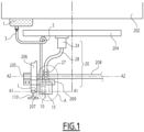
- Figure 1 schematically illustrates, seen in a front view, a lubricant apparatus, indicated by the overall reference number 100, for lubricating rails of a railway line.
- the various components of the lubricant apparatus 100 are mounted, as it will be described in further details hereinafter, on board on a railway vehicle, for example a wagon of train, schematically represented in figure 1 by the overall reference number 200.
- the railway vehicle 200 comprises:
- Couple of wheels such as the wheel 206, are mounted at the opposite sides of an associated mounting axle 208 which extends along an axis A2 transversal with respect to the longitudinal extension of the rails 110.
- the lubricant apparatus comprises at least:
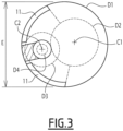
- the nozzle 10 comprises one more opening(s), e.g. slots, indicated in figure 3 by the reference number 11, which are arranged to dispense outwardly the lubricant onto a desired portion of the rail 110.
- opening(s) e.g. slots, indicated in figure 3 by the reference number 11, which are arranged to dispense outwardly the lubricant onto a desired portion of the rail 110.
- the nozzle 10 with its opening(s) 11 are arranged so that the flow of lubricant is spread selectively onto the portion of the rail 110, indicated in figure 1 by the letter L, constituting the contact interface with the flange 207 of an associated wheel 206 bearing over it when the railway vehicle 200 is travelling.
- the apparatus 100 further comprises an air blowing system, indicated in figure 1 by the overall reference number 20, which includes at least air blowing means.
- the air blowing means are positioned relative to nozzle 10 so that to blow air towards the nozzle 10 and cause the lubricant to be ejected out from the one or more openings 11 onto the desired portion L of the rail 110.
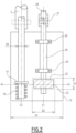
- the blowing means comprise an impeller 22; in the exemplary embodiment illustrated, the impeller 22 is schematically represented in figure 2 positioned inside a circular envelope 23 having a dimeter D2.
- the impeller 22 and the nozzle 10 are mounted spaced apart and substantially aligned to each other along a mounting axis A1 transversal with respect to the longitudinal extension of the rails 110.
- the mounting axis A1 is substantially parallel to the axis A2 of the wheel axle 208.
- the nozzle 10 and the impeller 22 are mounted offset ahead or aback the wheels of the railway vehicle 200.
- the nozzle 10 and the impeller 22 are mounted on the railway vehicle 200 ahead of the associated wheel 206 when the railway vehicle is travelling in one direction; clearly, if the railway vehicle 200 is proceeding in the opposite direction, then with respect to such opposite direction, the nozzle 10 and the impeller 22 result mounted aback or behind the wheel 206.
- the body of the wheel 206 is not interposed between the rail 110 and the nozzle 10.
- a mounting bracket 209 which is fixed at one end to the axle box 205, and is suitably shaped to extend from the box 205 around the front -or alternatively the back- part of the wheel 206.
- the mounting bracket 209 extends for example along a longitudinal direction parallel to the axis A1 and supports a cover 15 connected therewith.
- the cover e.g. of a substantially circular form and having for instance a diameter D1 as indicated in figures 2 and 3 , covers at least partially the nozzle 10 and the impeller 22, and is open at least on the side facing the rail 110.
- the air blowing system 20 of the lubricant apparatus 100 further comprises:
- the motor 24 can be for example any suitable motor available on the market, having for instance a speed up to 10000 rpm.
- the flexible shaft can be also any suitable type of shaft available on the market, e.g. a thin flexible shaft made of steel.
- Suitable bearings schematically represented in figure 2 by the reference number 29, allow the spindle 26 to rotate relative to the cover 15, around the axis C1.
- the lubricant apparatus 100 further comprises a conduit 3, e.g. a flexible hose or pipe having an inner diameter D4, which connects the tank 1 with the nozzle 10, and valve means 12 that are operatively connected to the nozzle 10.
- a conduit 3 e.g. a flexible hose or pipe having an inner diameter D4
- valve means 12 that are operatively connected to the nozzle 10.
- the valve means 22 are movable between a first position where they impede the flow of lubricant from the conduit 3 into the nozzle 10, and a second position where they means allow the lubricant to flow from the conduit 3 into the nozzle 10.
- the lubricant apparatus 100 further comprises a pump 5, preferably a positive displacement pump, which is arranged to push, once operated, lubricant to flow along the conduit 3 towards and up into the nozzle 10.
- a pump 5 preferably a positive displacement pump, which is arranged to push, once operated, lubricant to flow along the conduit 3 towards and up into the nozzle 10.
- valve means 12 comprises a piston 14, positioned at an end of the conduit 3 which is connected to the nozzle 10, and a spring 16, e.g. a soft spring, which is operatively connected to and interacts with the piston 14.
- a spring 16 e.g. a soft spring
- the piston 22 is mounted to move for a distance (d) along the axis C2; in particular, when the pump 5 is not active, the piston 14 is arranged to remain in said first position under the action of the spring 16, whereas under the action of the lubricant pushed by the pump 5, it moves downwardly in the second position, thus allowing flows of lubricant to enter into the nozzle 10.
- the pump 5 and the motor 24 are operated substantially synchronously to each other, and when the pump is actuated to push the lubricant and cause it to enter into the nozzle 10, also the motor 24 is actuated to properly start rotating the impeller 22.
- the functioning of the pump 5 and the motor 24 can be started for instance by a control unit (not illustrated in the figures) installed on board of the railway vehicle 200, which can be suitably programmed to start lubricating operations at desired interval of times during the travel, and/or to be actuated also by an operator.
- a control unit not illustrated in the figures
- the one or more openings 11 are properly configured to define, as a whole, an ejecting area, indicated in figure 3 for the sake of illustration by the capital letter E, from where the lubricating is selectively directed towards and onto the desired portion L of the rail 110.
- a plurality of apparatuses 100 can be installed on board of the same vehicle, or on board of different vehicles of a convoy or train.
- the apparatus 100 and related railway vehicle 200 according to the present invention allow achieving the intended aim since the lubrication of rails is carried out more efficiently and requires requiring a substantial less amount of lubricant with respect to known solutions, thus reducing consumption and waste of lubricants.
- the apparatus 100 and railway vehicle 200 thus conceived are susceptible of modifications and variations, all of which are within the scope of the inventive concept as defined in particular by the appended claims; for example, in relation to the specific application, some of the components can be differently configured or differently positioned.
- the motor 24 has been illustrated mounted beneath the frame 204 of a bogie, while the tank 1 has been illustrated fixed under the car body 202, but clearly and easily they could be positioned differently if desired or needed.
- the cover 15 and/or the envelope 23 can be differently shaped and/or can be realized in a single piece. The position, size, shape and number of each opening 11 can be properly selected according to the specific applications and/or specific needs.
Landscapes
- Engineering & Computer Science (AREA)
- Mechanical Engineering (AREA)
- Lubricants (AREA)
Applications Claiming Priority (1)
| Application Number | Priority Date | Filing Date | Title |
|---|---|---|---|
| IN202241022090 | 2022-04-13 |
Publications (1)
| Publication Number | Publication Date |
|---|---|
| EP4261102A1 true EP4261102A1 (fr) | 2023-10-18 |
Family
ID=86006518
Family Applications (1)
| Application Number | Title | Priority Date | Filing Date |
|---|---|---|---|
| EP23167489.6A Pending EP4261102A1 (fr) | 2022-04-13 | 2023-04-12 | Dispositif de lubrification pour la lubrification des rails d'une ligne de chemin de fer et véhicule ferroviaire comprenant un tel dispositif de lubrification |
Country Status (1)
| Country | Link |
|---|---|
| EP (1) | EP4261102A1 (fr) |
Cited By (1)
| Publication number | Priority date | Publication date | Assignee | Title |
|---|---|---|---|---|
| CN117360555A (zh) * | 2023-12-05 | 2024-01-09 | 中车浦镇阿尔斯通运输系统有限公司 | 单轨车辆稳定轮支架偏转结构 |
Citations (3)
| Publication number | Priority date | Publication date | Assignee | Title |
|---|---|---|---|---|
| FR988232A (fr) * | 1949-06-13 | 1951-08-24 | Sncf | Dispositif de graissage de rails à commande mécanique |
| EP0703135A1 (fr) * | 1994-09-24 | 1996-03-27 | De Limon Fluhme Gmbh | Buse de pulvérisation pour la lubrification d'un profile de roue d'un véhicule ferroviaire |
| WO2002087806A2 (fr) * | 2001-04-27 | 2002-11-07 | Lubriquip, Inc. | Systeme de lubrification de rail |
-
2023
- 2023-04-12 EP EP23167489.6A patent/EP4261102A1/fr active Pending
Patent Citations (3)
| Publication number | Priority date | Publication date | Assignee | Title |
|---|---|---|---|---|
| FR988232A (fr) * | 1949-06-13 | 1951-08-24 | Sncf | Dispositif de graissage de rails à commande mécanique |
| EP0703135A1 (fr) * | 1994-09-24 | 1996-03-27 | De Limon Fluhme Gmbh | Buse de pulvérisation pour la lubrification d'un profile de roue d'un véhicule ferroviaire |
| WO2002087806A2 (fr) * | 2001-04-27 | 2002-11-07 | Lubriquip, Inc. | Systeme de lubrification de rail |
Cited By (1)
| Publication number | Priority date | Publication date | Assignee | Title |
|---|---|---|---|---|
| CN117360555A (zh) * | 2023-12-05 | 2024-01-09 | 中车浦镇阿尔斯通运输系统有限公司 | 单轨车辆稳定轮支架偏转结构 |
Similar Documents
| Publication | Publication Date | Title |
|---|---|---|
| CA2235640C (fr) | Systemes de lubrification embarques pour lubrifier le dessus des rails pour les voitures et le cote interieur des rails/les boudins de roue pour les locomotives | |
| US5477941A (en) | On-board lubrication system for direct application to curved and tangent railroad track | |
| US6893058B2 (en) | Railway train friction management and control system and method | |
| CA2597375C (fr) | Procede et systeme permettant de limiter l'utilisation de sable dans un systeme de sablage de chemin de fer | |
| US6854563B2 (en) | Wayside rail lubrication apparatus and method | |
| EP1226059B1 (fr) | Graisseur de roues de bord de voie | |
| EP4261102A1 (fr) | Dispositif de lubrification pour la lubrification des rails d'une ligne de chemin de fer et véhicule ferroviaire comprenant un tel dispositif de lubrification | |
| US6182793B1 (en) | Lubricant delivery system for lubricating rail wheel flanges | |
| CN100478192C (zh) | 铁路列车摩擦管理与控制系统及方法 | |
| CN108698614A (zh) | 用于牵引系统的系统及方法 | |
| EP0288589A1 (fr) | Motrice légère de tramway avec trains de roulement orientables moteurs ou porteurs à roue unique, et avec plancher surbaissé ininterrompu pour montée d'une seule marche | |
| US10358783B2 (en) | Rail conditioning system | |
| US6186411B1 (en) | Wheel flange lubrication nozzle | |
| RU2348557C1 (ru) | Устройство для нанесения смазки и модификатора трения на рельсы | |
| JP2011063175A (ja) | レール頭頂面及び車輪踏面の圧縮空気による清掃方法及びその装置 | |
| JP2012184829A (ja) | 構内機関車車輪の塗油装置 | |
| US2184969A (en) | Rail wetting device for railroads | |
| CN105416339A (zh) | 电动式曲线钢轨润滑剂涂覆车 | |
| JP4680089B2 (ja) | 摩擦調整装置及び摩擦調整方法 | |
| RU2288125C1 (ru) | Устройство для нанесения смазки и модификатора трения на рельсы | |
| US385631A (en) | Street-car -iv | |
| SU1158415A1 (ru) | Устройство дл очистки торцов ободов колес железнодорожных вагонов | |
| SU969805A1 (ru) | Железнодорожный переезд Вершинина | |
| US1167514A (en) | Pneumatic flange-oiler for car-wheels. | |
| RU2238207C1 (ru) | Устройство для смазки гребней колес колесной пары рельсового экипажа |
Legal Events
| Date | Code | Title | Description |
|---|---|---|---|
| PUAI | Public reference made under article 153(3) epc to a published international application that has entered the european phase |
Free format text: ORIGINAL CODE: 0009012 |
|
| STAA | Information on the status of an ep patent application or granted ep patent |
Free format text: STATUS: THE APPLICATION HAS BEEN PUBLISHED |
|
| STAA | Information on the status of an ep patent application or granted ep patent |
Free format text: STATUS: REQUEST FOR EXAMINATION WAS MADE |
|
| AK | Designated contracting states |
Kind code of ref document: A1 Designated state(s): AL AT BE BG CH CY CZ DE DK EE ES FI FR GB GR HR HU IE IS IT LI LT LU LV MC ME MK MT NL NO PL PT RO RS SE SI SK SM TR |
|
| 17P | Request for examination filed |
Effective date: 20230928 |
|
| RBV | Designated contracting states (corrected) |
Designated state(s): AL AT BE BG CH CY CZ DE DK EE ES FI FR GB GR HR HU IE IS IT LI LT LU LV MC ME MK MT NL NO PL PT RO RS SE SI SK SM TR |
|
| GRAP | Despatch of communication of intention to grant a patent |
Free format text: ORIGINAL CODE: EPIDOSNIGR1 |
|
| STAA | Information on the status of an ep patent application or granted ep patent |
Free format text: STATUS: GRANT OF PATENT IS INTENDED |
|
| INTG | Intention to grant announced |
Effective date: 20250710 |
|
| STAA | Information on the status of an ep patent application or granted ep patent |
Free format text: STATUS: THE APPLICATION IS DEEMED TO BE WITHDRAWN |