EP4261104A2 - Chaise-poussoir - Google Patents
Chaise-poussoir Download PDFInfo
- Publication number
- EP4261104A2 EP4261104A2 EP23195246.6A EP23195246A EP4261104A2 EP 4261104 A2 EP4261104 A2 EP 4261104A2 EP 23195246 A EP23195246 A EP 23195246A EP 4261104 A2 EP4261104 A2 EP 4261104A2
- Authority
- EP
- European Patent Office
- Prior art keywords
- extending
- legs
- push chair
- shaft
- central body
- Prior art date
- Legal status (The legal status is an assumption and is not a legal conclusion. Google has not performed a legal analysis and makes no representation as to the accuracy of the status listed.)
- Granted
Links
Images









Classifications
-
- B—PERFORMING OPERATIONS; TRANSPORTING
- B62—LAND VEHICLES FOR TRAVELLING OTHERWISE THAN ON RAILS
- B62B—HAND-PROPELLED VEHICLES, e.g. HAND CARTS OR PERAMBULATORS; SLEDGES
- B62B7/00—Carriages for children; Perambulators, e.g. dolls' perambulators
- B62B7/04—Carriages for children; Perambulators, e.g. dolls' perambulators having more than one wheel axis; Steering devices therefor
- B62B7/06—Carriages for children; Perambulators, e.g. dolls' perambulators having more than one wheel axis; Steering devices therefor collapsible or foldable
- B62B7/08—Carriages for children; Perambulators, e.g. dolls' perambulators having more than one wheel axis; Steering devices therefor collapsible or foldable in the direction of, or at right angles to, the wheel axis
- B62B7/086—Carriages for children; Perambulators, e.g. dolls' perambulators having more than one wheel axis; Steering devices therefor collapsible or foldable in the direction of, or at right angles to, the wheel axis becoming smaller in all three dimensions
-
- B—PERFORMING OPERATIONS; TRANSPORTING
- B62—LAND VEHICLES FOR TRAVELLING OTHERWISE THAN ON RAILS
- B62B—HAND-PROPELLED VEHICLES, e.g. HAND CARTS OR PERAMBULATORS; SLEDGES
- B62B7/00—Carriages for children; Perambulators, e.g. dolls' perambulators
- B62B7/04—Carriages for children; Perambulators, e.g. dolls' perambulators having more than one wheel axis; Steering devices therefor
- B62B7/06—Carriages for children; Perambulators, e.g. dolls' perambulators having more than one wheel axis; Steering devices therefor collapsible or foldable
- B62B7/062—Coupling unit between front wheels, rear wheels and handle
-
- B—PERFORMING OPERATIONS; TRANSPORTING
- B62—LAND VEHICLES FOR TRAVELLING OTHERWISE THAN ON RAILS
- B62B—HAND-PROPELLED VEHICLES, e.g. HAND CARTS OR PERAMBULATORS; SLEDGES
- B62B7/00—Carriages for children; Perambulators, e.g. dolls' perambulators
- B62B7/04—Carriages for children; Perambulators, e.g. dolls' perambulators having more than one wheel axis; Steering devices therefor
- B62B7/06—Carriages for children; Perambulators, e.g. dolls' perambulators having more than one wheel axis; Steering devices therefor collapsible or foldable
-
- B—PERFORMING OPERATIONS; TRANSPORTING
- B62—LAND VEHICLES FOR TRAVELLING OTHERWISE THAN ON RAILS
- B62B—HAND-PROPELLED VEHICLES, e.g. HAND CARTS OR PERAMBULATORS; SLEDGES
- B62B9/00—Accessories or details specially adapted for children's carriages or perambulators
- B62B9/20—Handle bars; Handles
-
- B—PERFORMING OPERATIONS; TRANSPORTING
- B62—LAND VEHICLES FOR TRAVELLING OTHERWISE THAN ON RAILS
- B62B—HAND-PROPELLED VEHICLES, e.g. HAND CARTS OR PERAMBULATORS; SLEDGES
- B62B2205/00—Hand-propelled vehicles or sledges being foldable or dismountable when not in use
- B62B2205/003—Hand-propelled vehicles or sledges being foldable or dismountable when not in use with actuation mechanisms which drive the folding or unfolding operation
-
- B—PERFORMING OPERATIONS; TRANSPORTING
- B62—LAND VEHICLES FOR TRAVELLING OTHERWISE THAN ON RAILS
- B62B—HAND-PROPELLED VEHICLES, e.g. HAND CARTS OR PERAMBULATORS; SLEDGES
- B62B2205/00—Hand-propelled vehicles or sledges being foldable or dismountable when not in use
- B62B2205/02—Hand-propelled vehicles or sledges being foldable or dismountable when not in use foldable widthwise
-
- B—PERFORMING OPERATIONS; TRANSPORTING
- B62—LAND VEHICLES FOR TRAVELLING OTHERWISE THAN ON RAILS
- B62B—HAND-PROPELLED VEHICLES, e.g. HAND CARTS OR PERAMBULATORS; SLEDGES
- B62B2205/00—Hand-propelled vehicles or sledges being foldable or dismountable when not in use
- B62B2205/18—Geared articulations
-
- B—PERFORMING OPERATIONS; TRANSPORTING
- B62—LAND VEHICLES FOR TRAVELLING OTHERWISE THAN ON RAILS
- B62B—HAND-PROPELLED VEHICLES, e.g. HAND CARTS OR PERAMBULATORS; SLEDGES
- B62B5/00—Accessories or details specially adapted for hand carts
- B62B5/06—Hand moving equipment, e.g. handle bars
- B62B5/067—Stowable or retractable handle bars
Definitions
- the present invention relates to a push chair, in particular a push chair with an improved folding mechanism.
- Push Chairs are well known for transporting small children and modern push chairs can also be used and adapted for the carriage of babies.
- the term push chair is intended also to include what are also commonly referred to as strollers or buggies and is also intended to describe a system comprising a chassis to which can be added a seat or a removable cot or other enclosure suitable for the transport of a baby or a small child.
- One of the desired features of a pushchair is that it can be folded to a compact dimension, so making it easier to carry, stow in a car or other transport means, such as a bus, train or aircraft.
- US2014/0312599 describes a foldable type of push chair, but in this case foldable to a backpack.
- the front legs are also foldable to help reduce the overall dimensions.
- DE3147657A (Mocking ) describes an arrangement having a combination of rods connected to the main support structures for providing the support, the rods being slidably connected to the support to ensure the correct relationship between the support rods.
- a foldable push chair comprising a central body assembly extending across the push chair substantially horizontally and perpendicularly to the normal direction of travel of the push chair, a handle assembly connected to the central body and extending therefrom; at least three wheel supporting legs rotatable around the central body and extending from the central body, in the unfolded state one or more wheel supporting legs extending in a forward direction from the central body and one or more wheel supporting legs extending in a rearward direction from the central body; the forward and rearward extending legs being coupled together such that they rotate in opposite directions around the central body during a folding or unfolding operation.
- the present invention provides a means of ensuring the components comprising the wheel supporting legs fold and unfold easily and smoothly.
- a push chair is provided with at least one forward extending leg and the at least one rearward extending legs are connected together by a gearing system.
- the gearing system connecting the forward extending legs and rearward extending legs comprises a main shaft, a countershaft and an idler shaft, all having spur gears mounted thereon.
- the gearing system connecting the forward extending legs and rearward extending legs comprises an epicyclic gearing system.
- a particular advantage of the use of a gearing system for connecting the forward and rearward extending wheel supporting legs is that it enables the rotation of the wheel supporting legs to be controlled, smooth and avoids the need for sliding bars and other supports in which fingers of users, items of clothing or other things can be trapped or entangled. It also provides for a more neat and compact design than often seen elsewhere.
- a push chair further comprises a shaft extending through the central body assembly and whose longitudinal axis is co-incident with the axis extending through the central body assembly, the forward and rearward extending wheel supporting legs being mounted on said shaft.
- a push chair further comprises either two forward extending legs or two rearward extending legs, each of the either forward or rearward extending legs mounted on the shaft such that a plane of rotation of the legs around the axis is not perpendicular to the axis of the shaft and is such that in the folded state, distal ends of the wheel supporting legs are closer together than in the unfolded state.
- the rearwardly extending or forwardly extending legs can be rotated in the folded position to have a smaller distance between them than in the unfolded condition and so provide a push chair that folds more compactly in all three dimensions than other known products.
- a push chair is provided with either two forward extending legs or two rearward extending legs securely mounted on the shaft rotatable about the axis and rotating together in the same direction; the other of the rearward extending legs or forward extending legs being mounted on a second shaft co-axial with the shaft, the shaft and the second shaft connected by gear means so that the forward extending legs and rearward extending legs rotate in opposite directions during a folding or unfolding operation.
- a push chair according to any preceding Claim having two forward extending legs and two rearward extending legs.
- a push chair in which the shaft is articulated in a central region of the central body assembly, each arm of the shaft extending from the central region of the central body assembly to an outer part of the central body assembly and inclined to the horizontal to form a "V" shape, each arm supporting one forward and one rearward extending leg.
- an articulated shaft having a "V" shape articulated in the central region of the central body assembly enables the shaft to be articulated and the wheel supporting legs to be mounted on the shaft in a manner which results in a more compact form when they are folded than in a conventional arrangement.
- a push chair is provided an articulated shaft in which the articulation between the two parts of the shaft is by means of either a universal joint, or a gearing system, or an elastomeric connector or a woven metal mesh of tubular construction secured to each shaft.
- a push chair has a gearing system mounted on at least one of the arms of the shaft towards a distal end away from the articulating connection.
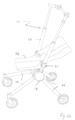
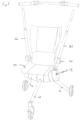
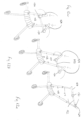
- FIG 1a shows a push chair according to the present invention in the unfolded state.
- Figure 1b shows a back rest of a seat portion in a semi-reclined position.
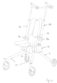
- Figures 1c and 1d show different side views of the pushchair.
- the push chair 10 comprises a central chassis assembly 12, a forward extending leg 14 and a rearward extending leg 16 and a handle 26 all mounted on the central chassis assembly 12.
- the forward extending legs and rearward extending legs are rotatable about an axis 12a passing through the central chassis assembly.
- a seat assembly 28 is mounted on the handle 26 by seat mounting means 30. As can be seen, normally the seat will be in a substantially upright position, but can be reclined at least partially as shown in Figure 1b .
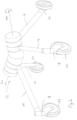
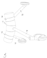
- FIG. 2 shows the central chassis assembly 12, which can be clearly seen is in the shape of a "V" extending across the chassis in a direction substantially perpendicular to the normal direction of travel.
- a forward extending leg 14 and a rearward extending leg 16 extend from a first arm of the V and a second forward extending leg 14 and a second rearward extending leg 16 extend from a second arm of the V.
- handle portions comprising the handle 26 which would be mounted on each arm of the V of the central chassis assembly 12 to facilitate the pushing and manoeuvring of the push chair are not shown here.
- Front wheel assemblies 18 At distal ends of the forward extending legs 14 are front wheel assemblies 18 and at distal ends of rearward extending legs 16 are rear wheel assemblies 20. Normally the rear wheel assemblies are arranged so that rear wheels 24 can rotate about a substantially horizontal axis. Front wheel assemblies 18 include front wheels 22 that can rotate about the normally horizontal axis and are additionally arranged so that they can rotate about a substantially vertical axis, so providing a potential steering facility in order to increase the manoeuvrability of the push chair.
- a particular advantage of mounting the wheel supporting legs on a V shape chassis is that it facilitates the folding of the push chair assembly into a smaller volume than might be possible with other and known arrangements without compromising the strength or utility of the unfolded push chair. More particularly, it enables the push chair of the present invention to be folded so that it is smaller in all three dimensions when folded than in the unfolded state, so enabling it to be more easily stored or transported than a similar design in which the central chassis extends only in a straight line.
- Figure 3a shows one arm of the V shaped central chassis with the forward extending leg 14 and the rearward extending leg 16 in the unfolded position.
- Figure 3b shows how the two legs can be rotated about the axis 12a to fold and form a compact folded arrangement.
- Figure 4a shows a perspective view of the folded push chair, which as can be seen has particularly compact dimensions.
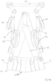
- Figure 4b shows a plan view of the folded push chair.
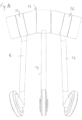
- Figure 4c shows the push chair chassis in the unfolded condition from a front view; and 4d shows a plan view of the folded push chair chassis.
- the width of the folded push chair is noticeably less than in the unfolded state.
- Forward extending legs 14 and the rearward extending legs 16 are mounted on bearing means which enable them to be rotated about axis 12a to move between the folded and unfolded positions described in more detail below.
- the forwardly extending legs 14 and rearwardly extending legs 16 are connected together by gearing means that ensure they rotate in synchronism.
- the folding assembly and mechanism relies upon wheel supporting legs and other supporting or cross-bracing arms connected together with linkage mechanisms that are engaged with pivotable and/or slidable connections to maintain the relative positions between the various arms and legs.
- Such complex connections between the arms and legs require careful operation and users find that users fingers or other objects can become caught or trapped in the sliding or pivoting components. This is at best inconvenient and worse can be painful and cause injury if the items being caught are fingers or other parts of a user's body.
- a particular advantage of the present invention is that the folding mechanism does not use or rely upon one or more sliding arms or pivoting components to assist in folding the forward or rearward extending legs and such sliding arrangements are not required to maintain the strength and structural integrity of the push chair according to the present invention.
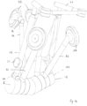
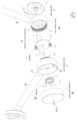
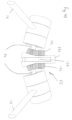
- FIG. 5 shows an expanded view of a gearing arrangement used in the push chair to ensure the operation of the folding or unfolding of the push chair.
- the arrangement comprises an epicyclic gear assembly, detailed construction and operation of which is explained below.
- the figure shows the arrangement on one arm of the V shaped chassis, the same type of arrangement can be used on the other arm, but is not shown for the purposes of simplicity.
- Each arm of the chassis defines an axis of rotation 12a of the forward and rearward extending legs 14 and 16.
- a shaft 50 extends along the axis 12a.
- Shaft 50 is connected to a corresponding shaft in the other arm of the V by a universal joint or universal swivel coupling 52.
- FIG. 5a shows the swivel joint is replaced by a simple pair of bevel gears 51, each mounted on one of the shafts 50, the gears engaging to ensure coupled rotation of the shafts.
- Further examples of the coupling could be any of a flexible elastomeric material, a device similar in construction to an automotive constant velocity joint, a tube of a woven metal mesh capable of transmitting torque.
- Forward extending leg 14 has a hub portion 54 comprising the end of the leg and rotatably mounted on the shaft 50 extending through central chassis 12.
- the hub 54 is provided with internal spur gear teeth 58 comprising the annulus of the gear assembly.
- An internal chassis 60 is rotatably mounted on shaft 50.
- Planet gears 62 are mounted on the internal chassis so that they engage with the spur gear teeth 58 of the annulus.
- Rearwardly extending leg 16 also has a hub portion 56 where it is mounted on the shaft 50 of the chassis 12.
- the hub portion 56 is provided with a set of external facing spur gear teeth 64 comprising the sun portion of the gear train which engage with the planet gears 62.
- the internal chassis 60 includes tongues 61 extending therefrom in a plane substantially parallel to the axis 12a, the tongues engaging in slots 63, 65 respectively in hubs 54 and 56 to limit the rotation of the internal chassis with respect to the hubs.
- a cover unit 66 is provided at the end shaft 50 to protect the gear assembly.
- the cover unit also provides a hub for mounting the handle 26 (not shown) which extends therefrom.
- a further improvement to the push chair is provided by the addition of a spring 68, which, depending on the chosen configuration can be used to assist the folding or unfolding of the push chair.
- the spring shown is a coil spring in which a central axis of the coil is parallel to, if not co-axial with, the axis 12a.
- the spring 68 has end parts or arms 70, 72 which each extend away tangentially from the central axis of the coil to provide stabilising or mounting arms.
- One of the arms 70 engages with a retaining stop 74 in the hub 56, the other arm 72 engages in a retaining slot or hole 76 in cover assembly 66.
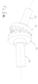
- Figure 6 shows a close up view of the epicyclic gear assembly partially assembled and in which the internal chassis 60 is located inside the hub 54 and the planet gears 62 are engaged with gears 58 of the annulus.
- FIG. 7a shows a cut away drawing of an assembly using an alternative gearing arrangement comprising a main shaft and countershaft arrangement.
- gear systems are commonly found in many applications, such as automotive transmissions or gearboxes.
- a main shaft 80 extends along the line defined by the central axis 12a.
- a spur gear 82 is mounted on the main shaft 80 and either secured to the hub portion 54 of the forwardly extending leg 14 or forms an integral part of it.
- Spur gear 82 in turn engages with a countershaft gear 84 mounted on a countershaft 86 (also known as a layshaft) supported in a countershaft chassis 88.
- Countershaft 86 is supported by and extends through the chassis 88 and includes a second countershaft spur gear 90 which in turn engages with an idler gear 92 on an idler shaft (not shown separately).
- the idler shaft is also supported in the countershaft chassis.
- a second idler gear 93 is also mounted on the idler shaft and engages with a second spur gear 94 connected to the hub 56 of the rearwardly extending leg 16.
- the idler gear 93 is in turn engaging with second spur gear 94 in the hub 56 of the rearwardly extending leg 16 and so caused to rotate in the opposite direction to the rotation of the idler gear.
- the forward extending and rearward extending legs are on the same axis, so presenting a very compact arrangement for the chassis when folded.
- main shaft is connected to the hubs of the forward or rearward extending legs and which gear is connected to the idler gears; the operation and result is the same.
- Figure 7b shows this operation in greater detail on a larger scale.
- Figure 7c shows the design without the supporting chassis 88.
- the countershaft 86 and second countershaft gear 90 can be clearly seen.
- the arrangement for the idler gears 92 and 93 and their shaft can be clearly seen.
- the shaft 50 extends through a central region of the chassis and either both forward extending legs are securely mounted on the shaft, and the rearward extending legs are rotatably mounted on the shaft and driven by the gearing system to rotate in the opposite direction to the forward extending legs; or the rearward extending legs are securely mounted on the shaft, and the forward extending legs are rotatably mounted on the shaft and driven by the gearing system to rotate in the opposite direction to the rearward extending legs.
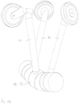
- the concept of a single central chassis with forward and rearward extending legs can also be applied to a three wheel design push chair as shown in Figure 8 .
- the push chair has one forward extending leg and two rearward extending legs.
- the other components have the same numbering as used in the earlier description.
- Figure 9a shows an example of a three wheel chassis alone, without the handle and seat mounting means
- Figure 10 shows the three wheel push chair chassis in a partially folded condition.
- Figures 9b and 9c show alternative means of connecting the shafts 50 together so that they both rotate in the same direction at the same time.
- Figure 9b shows an alternative gear system, which includes a separate supporting chassis 130. Bevel gears at the end of each shaft 50 engage bevelled idler gears 132 mounted on an idler shaft 134 in the supporting chassis. This arrangement would be particularly suitable in the event a three wheel design is chosen. In the case of a three wheel design, a central wheel supporting leg could be mounted on the idler shaft 134 in the supporting chassis 132.
- Figure 9c shows a perspective view of Figure 9b . For the sake of clarity, the central wheel supporting leg and wheel assembly is not shown. From the figure it will be apparent that the central wheel supporting leg could be mounted on the shaft 134 so that it rotated with the shaft. This construction would ensure the central wheel supporting leg would rotate in the opposite direction to the rearward extending legs 16.
- Figure 10 shows a perspective side view of the folded arrangement of a three wheeled design.
- Figure 11 shows a plan view of the folded arrangement of a three wheeled design.
- Figures 12a-c show a general view of the handle assembly. From these drawings it can be seen that the handle assembly is provided with multiple articulation points which enable it to be folded to a more compact dimension and in particular a narrower width than the unfolded push chair.
- Figure 12a shows the handle in the fully extended position.
- Figure 12b shows an intermediate folded position, and Figure 12c a second intermediate folded position.
- articulation parts 150 enable the handle to extend across a top part of the push chair and are seen to be extended to maintain the handle in a generally open position.
- the articulation parts can be seen to be rotating the handle to a more compact arrangement as side handle pieces 154 are rotated inwards as shown in the figures.
- the handle can be reduced in height.
- Upper handle arms 156 are arranged to be nested telescopically with lower handle arms 158 and so the upper part 156 will slide into the lower part 158 during the folding process. The reverse operation occurs during the unfolding.
- a number of different detailed schemes can be envisaged for arranging for the upper and lower parts to cooperate slidably to reduce the height of the handle assembly and latch in place in either or both of the upper and lower positions.
- Latching arrangements can be incorporated to the handle assembly to ensure it remains in its folded or unfolded state.
- Figure 13 illustrates another alternative embodiment in which the V shaped chassis is replaced by a linear chassis having a single linear axis. This could make the gearing system simpler for a three legged variant and avoid the need for a universal swivel coupling in the chassis since a straight shaft could be used.
- the handle and seat assembly are not shown for convenience, but could be attached as illustrated in other embodiments. Whilst the figure only shows a three wheel chassis, it is readily apparent it could be easily adapted to a four wheel design.
- the forward extending legs would each be mounted on one of a pair of co-axial shafts and rearward extending legs would be mounted on the other of the co-axial shafts, the co-axial shafts connected together by gearing mechanisms of the type described above in order to ensure the legs rotate in opposite directions during a folding and unfolding operation.
- This configuration is particularly suited to an epicyclic type gearing system, which would permit a particularly compact design to be employed.
- Figure 14 shows the chassis of Figure 13 folded to its compact dimensions.
- the rearward extending legs can be mounted on the chassis such that the plane of rotation of the legs is not perpendicular to the axis of the central axis 12a. If mounted in this manner, the legs do not extend perpendicularly from the axis 12 but are splayed outward at an angle to it so that in the extended position the track distance between the wheels is greater than the distance between the wheels when folded as can be seen in Figure 13 .
- the legs are rotated and folded, as shown in Figure 14 , it can be seen the folded dimensions of the push chair are more compact than in the unfolded state.
- a universal coupling or other means to connect each arm of the "V" is not needed.
- a single main shaft could then be used extending across the width of the chassis with either both forward extending legs mounted securely on it, or both rearward extending legs securely mounted on it and the other of the two legs rotatably driven by the gear system described above to rotate in the opposite direction.
- the handle assembly can also be folded to be less wide than the push chair.
Landscapes
- Engineering & Computer Science (AREA)
- Chemical & Material Sciences (AREA)
- Combustion & Propulsion (AREA)
- Transportation (AREA)
- Mechanical Engineering (AREA)
- Health & Medical Sciences (AREA)
- Public Health (AREA)
- Special Chairs (AREA)
- Carriages For Children, Sleds, And Other Hand-Operated Vehicles (AREA)
- Chairs For Special Purposes, Such As Reclining Chairs (AREA)
- Handcart (AREA)
- Compositions Of Oxide Ceramics (AREA)
Applications Claiming Priority (4)
| Application Number | Priority Date | Filing Date | Title |
|---|---|---|---|
| GB1815203.3A GB2591211B (en) | 2018-09-18 | 2018-09-18 | A push chair |
| GBGB1821001.3A GB201821001D0 (en) | 2018-09-18 | 2018-12-21 | A push chair |
| PCT/IB2019/000770 WO2020058753A1 (fr) | 2018-09-18 | 2019-09-18 | Poussette |
| EP19795305.2A EP3853102B1 (fr) | 2018-09-18 | 2019-09-18 | Poussette |
Related Parent Applications (1)
| Application Number | Title | Priority Date | Filing Date |
|---|---|---|---|
| EP19795305.2A Division EP3853102B1 (fr) | 2018-09-18 | 2019-09-18 | Poussette |
Publications (3)
| Publication Number | Publication Date |
|---|---|
| EP4261104A2 true EP4261104A2 (fr) | 2023-10-18 |
| EP4261104A3 EP4261104A3 (fr) | 2024-01-03 |
| EP4261104B1 EP4261104B1 (fr) | 2026-01-21 |
Family
ID=64013399
Family Applications (2)
| Application Number | Title | Priority Date | Filing Date |
|---|---|---|---|
| EP19795305.2A Active EP3853102B1 (fr) | 2018-09-18 | 2019-09-18 | Poussette |
| EP23195246.6A Active EP4261104B1 (fr) | 2018-09-18 | 2019-09-18 | Poussette |
Family Applications Before (1)
| Application Number | Title | Priority Date | Filing Date |
|---|---|---|---|
| EP19795305.2A Active EP3853102B1 (fr) | 2018-09-18 | 2019-09-18 | Poussette |
Country Status (17)
| Country | Link |
|---|---|
| US (1) | US11760402B2 (fr) |
| EP (2) | EP3853102B1 (fr) |
| JP (1) | JP7623701B2 (fr) |
| KR (1) | KR102894935B1 (fr) |
| CN (3) | CN113382912A (fr) |
| AU (1) | AU2019344090B2 (fr) |
| CA (1) | CA3113001A1 (fr) |
| DK (2) | DK3853102T3 (fr) |
| ES (1) | ES2967232T3 (fr) |
| GB (2) | GB2591211B (fr) |
| IL (1) | IL281510A (fr) |
| MX (1) | MX2021003162A (fr) |
| PL (1) | PL3853102T3 (fr) |
| PT (1) | PT3853102T (fr) |
| SA (1) | SA521421519B1 (fr) |
| SG (1) | SG11202102662XA (fr) |
| WO (1) | WO2020058753A1 (fr) |
Families Citing this family (5)
| Publication number | Priority date | Publication date | Assignee | Title |
|---|---|---|---|---|
| US11577132B2 (en) * | 2019-08-23 | 2023-02-14 | Walker Trolleys, LLC | Collapsible golf trolley |
| GB2603742B (en) * | 2020-11-16 | 2023-11-08 | Jijibaba Ltd | Leg folding mechanism |
| USD1054143S1 (en) | 2021-12-20 | 2024-12-10 | GoBuggy Ltd. | Foldable cart |
| GB2640583A (en) | 2024-04-26 | 2025-10-29 | Jijibaba Ltd | A vehicle, a method of folding a vehicle and a method and system for locking a vehicle |
| GB2640584A (en) | 2024-04-26 | 2025-10-29 | Jijibaba Ltd | A vehicle, a push chair and a method of folding a vehicle such as a push chair |
Citations (2)
| Publication number | Priority date | Publication date | Assignee | Title |
|---|---|---|---|---|
| DE3147657A1 (de) | 1981-12-02 | 1983-06-09 | Hermann 4800 Bielefeld Möcking | "faltbarer kinderwagen" |
| US20140312599A1 (en) | 2013-01-21 | 2014-10-23 | Helen Millman-Wood | Convertible stroller assembly |
Family Cites Families (47)
| Publication number | Priority date | Publication date | Assignee | Title |
|---|---|---|---|---|
| US3648795A (en) * | 1970-06-08 | 1972-03-14 | H Douglass Moulton | Three-wheeled electrically propelled cart |
| CA1202995A (fr) * | 1982-03-31 | 1986-04-08 | Abdelraouf M.S. Al-Sheikh | Poussette pliante |
| GB2399322B (en) | 2003-03-14 | 2006-02-01 | Kenny Cheng | Stroller |
| US20060267303A1 (en) | 2003-04-30 | 2006-11-30 | Matthew Golias | Collapsible supporting structure |
| DE60305311D1 (de) * | 2003-07-31 | 2006-06-22 | All Our Kids Europ B V | Verschlusssystem und Kinderwagen mit einem solchen System |
| CN1306155C (zh) * | 2003-08-12 | 2007-03-21 | 重庆隆鑫工业(集团)有限公司 | 摩托车内置自锁式倒档装置 |
| US20070096434A1 (en) | 2003-12-02 | 2007-05-03 | Christian Haeggberg | Collapsible stroller |
| NL1027054C2 (nl) * | 2004-09-16 | 2006-03-20 | Bugaboo Design And Sales B V | Buggy. |
| NZ553817A (en) | 2004-09-16 | 2010-09-30 | Mutsy Bv | Collapsible carriage, typically infant buggy, with pusher arms and/or wheeled legs connected to further pivoted link(s) |
| FR2882015B1 (fr) * | 2005-02-16 | 2008-09-26 | Dorel France Sa | Poussette pour enfant, a pliage parapluie |
| CN100387469C (zh) | 2005-04-30 | 2008-05-14 | 好孩子儿童用品有限公司 | 儿童推车 |
| AU2006244602A1 (en) * | 2005-05-05 | 2006-11-16 | Purdue Research Foundation | Vehicle with variable wheel camber |
| GB2431381B (en) | 2005-10-19 | 2008-01-30 | 100 Watt Ltd | Collapsible pushchair |
| ITTV20060024A1 (it) | 2006-03-03 | 2007-09-04 | Wip Srl | Passeggino avente un telaio pieghevole perfezionato. |
| WO2007103392A2 (fr) * | 2006-03-06 | 2007-09-13 | Purdue Research Foundation | Moyeu oscillant pour regler l'inclinaison laterale |
| CN101104414B (zh) * | 2007-07-25 | 2010-06-02 | 金点行销公司 | 婴儿车关节 |
| US7401803B1 (en) * | 2007-08-28 | 2008-07-22 | Chin-I Lai | Stroller |
| DE102007045068B3 (de) | 2007-09-19 | 2009-04-02 | Otto Bock Healthcare Ip Gmbh & Co. Kg | Kinder-Sportkarre |
| US8087689B2 (en) * | 2008-07-31 | 2012-01-03 | Cosco Management, Inc. | Compact collapsible stroller |
| EP2323889A4 (fr) | 2008-09-05 | 2013-09-25 | Thorley Ind Llc | Poussette pliable |
| JP5442729B2 (ja) * | 2009-06-12 | 2014-03-12 | コンビ株式会社 | ベビーカー |
| NL2004371C2 (en) | 2010-03-09 | 2011-09-13 | Maxi Miliaan Bv | A STROLLER. |
| ES2396886B1 (es) * | 2011-01-03 | 2014-01-20 | Jane, S.A. | Chasis para cochecitos infantiles con dos plazas. |
| ES1074637Y (es) * | 2011-01-25 | 2011-08-25 | Jane Sa | Dispositivo aplicable al plegado de coches-silla infantiles |
| US8485547B2 (en) * | 2011-12-07 | 2013-07-16 | Wei Guan Products Co., Ltd | Stroller having shock-absorbing function |
| US20130234418A1 (en) * | 2012-03-08 | 2013-09-12 | Sun Mountain Sports, Inc. | Collapsible golf bag cart with improved folding mechanism |
| GB2507507A (en) * | 2012-10-31 | 2014-05-07 | Russell Anthony Clifton | A ratchet and pawl mechanism for the folding handle of a stroller |
| JP5728457B2 (ja) * | 2012-10-31 | 2015-06-03 | 三木プーリ株式会社 | 撓み軸継手およびその製造方法 |
| TWM451161U (zh) * | 2012-11-05 | 2013-04-21 | Macauto Ind Co Ltd | 高爾夫球袋車 |
| CN103359146B (zh) | 2013-08-02 | 2016-06-22 | 中山市乐瑞婴童用品有限公司 | 婴儿车插接式座椅收折机构 |
| PT107371A (pt) * | 2013-12-18 | 2015-08-14 | Zyevolution Investigação E Desenvolvimento S A | Estrutura colapsável para carrinho de rua |
| CN203766857U (zh) * | 2014-03-27 | 2014-08-13 | 克斯克管理公司 | 推车 |
| DE102014110215A1 (de) | 2014-06-16 | 2015-12-17 | Cybex Gmbh | Kinderwagengestell und Kinderwagen |
| JP6490214B2 (ja) * | 2015-06-26 | 2019-03-27 | エレクター株式会社 | 台車装置 |
| JP6236131B2 (ja) * | 2015-11-23 | 2017-11-22 | 明門香港股▲フェン▼有限公司 | 幼児ベビーカー装置 |
| MX2018011533A (es) * | 2016-03-23 | 2019-01-28 | Ford Global Tech Llc | Carrito reconfigurable. |
| CN105946952B (zh) * | 2016-06-30 | 2018-06-19 | 晨辉婴宝儿童用品有限公司 | 婴儿车收车结构以及婴儿车 |
| GB2553802B (en) | 2016-09-14 | 2019-08-07 | Stroller Tech Ltd | A stroller |
| CN106347443B (zh) * | 2016-09-30 | 2019-06-25 | 东莞硕仕儿童用品有限公司 | 一种折叠婴儿手推车 |
| CN106347444B (zh) * | 2016-10-25 | 2018-12-07 | 苏州昂锐儿童用品有限公司 | 一种折叠后便于收纳的童车车架 |
| CN106891972A (zh) * | 2017-03-19 | 2017-06-27 | 张新 | 用于运载儿童的多悬挂多功能的设备和装置 |
| CN206968743U (zh) * | 2017-07-14 | 2018-02-06 | 张发辉 | 一种可折叠童车车架 |
| CN107226121B (zh) * | 2017-07-14 | 2023-04-07 | 张发辉 | 一种可折叠童车车架 |
| CN207328549U (zh) * | 2017-08-10 | 2018-05-08 | 中山市西区青原贸易代理服务部 | 婴儿车车架 |
| CN107757688B (zh) * | 2017-11-20 | 2024-05-24 | 中山恒之宝婴童用品有限公司 | 一种婴儿车 |
| CN108407875A (zh) * | 2018-03-20 | 2018-08-17 | 郑谦岳 | 婴儿推车 |
| US11577132B2 (en) * | 2019-08-23 | 2023-02-14 | Walker Trolleys, LLC | Collapsible golf trolley |
-
2018
- 2018-09-18 GB GB1815203.3A patent/GB2591211B/en active Active
- 2018-12-21 GB GBGB1821001.3A patent/GB201821001D0/en not_active Ceased
-
2019
- 2019-09-18 CN CN201980075819.5A patent/CN113382912A/zh active Pending
- 2019-09-18 SG SG11202102662XA patent/SG11202102662XA/en unknown
- 2019-09-18 CN CN202510603859.XA patent/CN120589074A/zh active Pending
- 2019-09-18 KR KR1020217011250A patent/KR102894935B1/ko active Active
- 2019-09-18 MX MX2021003162A patent/MX2021003162A/es unknown
- 2019-09-18 ES ES19795305T patent/ES2967232T3/es active Active
- 2019-09-18 US US17/277,445 patent/US11760402B2/en active Active
- 2019-09-18 AU AU2019344090A patent/AU2019344090B2/en active Active
- 2019-09-18 DK DK19795305.2T patent/DK3853102T3/da active
- 2019-09-18 PL PL19795305.2T patent/PL3853102T3/pl unknown
- 2019-09-18 JP JP2021538937A patent/JP7623701B2/ja active Active
- 2019-09-18 CN CN202510604216.7A patent/CN120621474A/zh active Pending
- 2019-09-18 PT PT197953052T patent/PT3853102T/pt unknown
- 2019-09-18 DK DK23195246.6T patent/DK4261104T3/da active
- 2019-09-18 EP EP19795305.2A patent/EP3853102B1/fr active Active
- 2019-09-18 WO PCT/IB2019/000770 patent/WO2020058753A1/fr not_active Ceased
- 2019-09-18 EP EP23195246.6A patent/EP4261104B1/fr active Active
- 2019-09-18 CA CA3113001A patent/CA3113001A1/fr active Pending
-
2021
- 2021-03-15 IL IL281510A patent/IL281510A/en unknown
- 2021-03-18 SA SA521421519A patent/SA521421519B1/ar unknown
Patent Citations (2)
| Publication number | Priority date | Publication date | Assignee | Title |
|---|---|---|---|---|
| DE3147657A1 (de) | 1981-12-02 | 1983-06-09 | Hermann 4800 Bielefeld Möcking | "faltbarer kinderwagen" |
| US20140312599A1 (en) | 2013-01-21 | 2014-10-23 | Helen Millman-Wood | Convertible stroller assembly |
Also Published As
| Publication number | Publication date |
|---|---|
| PL3853102T3 (pl) | 2024-03-11 |
| JP2022501267A (ja) | 2022-01-06 |
| JP7623701B2 (ja) | 2025-01-29 |
| GB201821001D0 (en) | 2019-02-06 |
| CN113382912A (zh) | 2021-09-10 |
| WO2020058753A1 (fr) | 2020-03-26 |
| CN120621474A (zh) | 2025-09-12 |
| MX2021003162A (es) | 2021-10-13 |
| US20210347400A1 (en) | 2021-11-11 |
| IL281510A (en) | 2021-04-29 |
| KR20210122222A (ko) | 2021-10-08 |
| US11760402B2 (en) | 2023-09-19 |
| EP3853102B1 (fr) | 2023-10-04 |
| GB2591211A (en) | 2021-07-28 |
| KR102894935B1 (ko) | 2025-12-03 |
| EP4261104A3 (fr) | 2024-01-03 |
| CN120589074A (zh) | 2025-09-05 |
| DK3853102T3 (da) | 2024-01-08 |
| CA3113001A1 (fr) | 2020-03-26 |
| AU2019344090B2 (en) | 2025-03-20 |
| EP3853102A1 (fr) | 2021-07-28 |
| SG11202102662XA (en) | 2021-04-29 |
| DK4261104T3 (da) | 2026-04-27 |
| SA521421519B1 (ar) | 2024-05-05 |
| BR112021005200A2 (pt) | 2021-06-08 |
| GB201815203D0 (en) | 2018-10-31 |
| ES2967232T3 (es) | 2024-04-29 |
| EP4261104B1 (fr) | 2026-01-21 |
| PT3853102T (pt) | 2024-01-09 |
| AU2019344090A1 (en) | 2021-04-15 |
| GB2591211B (en) | 2022-04-27 |
Similar Documents
| Publication | Publication Date | Title |
|---|---|---|
| EP4261104B1 (fr) | Poussette | |
| CN101400561B (zh) | 具有可伸缩把手的婴儿车 | |
| CN107685758B (zh) | 儿童推车 | |
| KR20200014844A (ko) | 유모차 | |
| US11643126B2 (en) | Foldable push chair | |
| CN101670844B (zh) | 一种婴儿推车 | |
| HK40058854B (en) | Push chair | |
| HK40058854A (en) | Push chair | |
| CN204871133U (zh) | 儿童推车 | |
| CN108032899A (zh) | 一种婴儿车 | |
| CN119370172A (zh) | 儿童推车 | |
| CN113665658B (zh) | 儿童推车 | |
| CN110937009A (zh) | 可折叠的车架以及童车 | |
| GB2623376A (en) | A push chair and a method of folding a push chair | |
| CN213534816U (zh) | 儿童推车 | |
| BR112021005200B1 (pt) | Cadeira de empurrar | |
| CN223370924U (zh) | 一种儿童推车骨架 | |
| US20260062045A1 (en) | Mini-stroller gear mechanism | |
| HK40058855B (en) | A foldable push chair | |
| HK40058855A (en) | A foldable push chair | |
| CN213292401U (zh) | 儿童推车 | |
| CN110001735B (zh) | 一种儿童推车 | |
| CN120440103A (zh) | 一种儿童推车骨架 | |
| CN107856728A (zh) | 儿童推车 |
Legal Events
| Date | Code | Title | Description |
|---|---|---|---|
| PUAI | Public reference made under article 153(3) epc to a published international application that has entered the european phase |
Free format text: ORIGINAL CODE: 0009012 |
|
| STAA | Information on the status of an ep patent application or granted ep patent |
Free format text: STATUS: THE APPLICATION HAS BEEN PUBLISHED |
|
| AC | Divisional application: reference to earlier application |
Ref document number: 3853102 Country of ref document: EP Kind code of ref document: P |
|
| AK | Designated contracting states |
Kind code of ref document: A2 Designated state(s): AL AT BE BG CH CY CZ DE DK EE ES FI FR GB GR HR HU IE IS IT LI LT LU LV MC MK MT NL NO PL PT RO RS SE SI SK SM TR |
|
| REG | Reference to a national code |
Ref country code: DE Ref legal event code: R079 Free format text: PREVIOUS MAIN CLASS: B62B0009200000 Ipc: B62B0007060000 Ref document number: 602019080563 Country of ref document: DE |
|
| PUAL | Search report despatched |
Free format text: ORIGINAL CODE: 0009013 |
|
| AK | Designated contracting states |
Kind code of ref document: A3 Designated state(s): AL AT BE BG CH CY CZ DE DK EE ES FI FR GB GR HR HU IE IS IT LI LT LU LV MC MK MT NL NO PL PT RO RS SE SI SK SM TR |
|
| RIC1 | Information provided on ipc code assigned before grant |
Ipc: B62B 5/06 20060101ALN20231127BHEP Ipc: B62B 9/20 20060101ALI20231127BHEP Ipc: B62B 7/08 20060101ALI20231127BHEP Ipc: B62B 7/06 20060101AFI20231127BHEP |
|
| STAA | Information on the status of an ep patent application or granted ep patent |
Free format text: STATUS: REQUEST FOR EXAMINATION WAS MADE |
|
| 17P | Request for examination filed |
Effective date: 20240628 |
|
| RBV | Designated contracting states (corrected) |
Designated state(s): AL AT BE BG CH CY CZ DE DK EE ES FI FR GB GR HR HU IE IS IT LI LT LU LV MC MK MT NL NO PL PT RO RS SE SI SK SM TR |
|
| GRAP | Despatch of communication of intention to grant a patent |
Free format text: ORIGINAL CODE: EPIDOSNIGR1 |
|
| STAA | Information on the status of an ep patent application or granted ep patent |
Free format text: STATUS: GRANT OF PATENT IS INTENDED |
|
| RIC1 | Information provided on ipc code assigned before grant |
Ipc: B62B 7/06 20060101AFI20250721BHEP Ipc: B62B 7/08 20060101ALI20250721BHEP Ipc: B62B 9/20 20060101ALI20250721BHEP Ipc: B62B 5/06 20060101ALN20250721BHEP |
|
| INTG | Intention to grant announced |
Effective date: 20250807 |
|
| GRAS | Grant fee paid |
Free format text: ORIGINAL CODE: EPIDOSNIGR3 |
|
| GRAA | (expected) grant |
Free format text: ORIGINAL CODE: 0009210 |
|
| STAA | Information on the status of an ep patent application or granted ep patent |
Free format text: STATUS: THE PATENT HAS BEEN GRANTED |
|
| AC | Divisional application: reference to earlier application |
Ref document number: 3853102 Country of ref document: EP Kind code of ref document: P |
|
| AK | Designated contracting states |
Kind code of ref document: B1 Designated state(s): AL AT BE BG CH CY CZ DE DK EE ES FI FR GB GR HR HU IE IS IT LI LT LU LV MC MK MT NL NO PL PT RO RS SE SI SK SM TR |
|
| REG | Reference to a national code |
Ref country code: CH Ref legal event code: F10 Free format text: ST27 STATUS EVENT CODE: U-0-0-F10-F00 (AS PROVIDED BY THE NATIONAL OFFICE) Effective date: 20260121 |
|
| REG | Reference to a national code |
Ref country code: DE Ref legal event code: R096 Ref document number: 602019080563 Country of ref document: DE |
|
| REG | Reference to a national code |
Ref country code: IE Ref legal event code: FG4D |
|
| REG | Reference to a national code |
Ref country code: CH Ref legal event code: R17 Free format text: ST27 STATUS EVENT CODE: U-0-0-R10-R17 (AS PROVIDED BY THE NATIONAL OFFICE) Effective date: 20260421 |
|
| REG | Reference to a national code |
Ref country code: DK Ref legal event code: T3 Effective date: 20260421 |