EP4261143A1 - Klebstoffauftragsvorrichtung und batterieproduktionslinie mit solch einer klebstoffauftragsvorrichtung - Google Patents
Klebstoffauftragsvorrichtung und batterieproduktionslinie mit solch einer klebstoffauftragsvorrichtung Download PDFInfo
- Publication number
- EP4261143A1 EP4261143A1 EP23165798.2A EP23165798A EP4261143A1 EP 4261143 A1 EP4261143 A1 EP 4261143A1 EP 23165798 A EP23165798 A EP 23165798A EP 4261143 A1 EP4261143 A1 EP 4261143A1
- Authority
- EP
- European Patent Office
- Prior art keywords
- adhesive
- adhesive application
- path
- release paper
- wheel
- Prior art date
- Legal status (The legal status is an assumption and is not a legal conclusion. Google has not performed a legal analysis and makes no representation as to the accuracy of the status listed.)
- Granted
Links
Images
Classifications
-
- H—ELECTRICITY
- H01—ELECTRIC ELEMENTS
- H01M—PROCESSES OR MEANS, e.g. BATTERIES, FOR THE DIRECT CONVERSION OF CHEMICAL ENERGY INTO ELECTRICAL ENERGY
- H01M10/00—Secondary cells; Manufacture thereof
- H01M10/04—Construction or manufacture in general
- H01M10/0404—Machines for assembling batteries
-
- B—PERFORMING OPERATIONS; TRANSPORTING
- B65—CONVEYING; PACKING; STORING; HANDLING THIN OR FILAMENTARY MATERIAL
- B65C—LABELLING OR TAGGING MACHINES, APPARATUS, OR PROCESSES
- B65C9/00—Details of labelling machines or apparatus
- B65C9/08—Label feeding
- B65C9/18—Label feeding from strips, e.g. from rolls
- B65C9/1865—Label feeding from strips, e.g. from rolls the labels adhering on a backing strip
- B65C9/1869—Label feeding from strips, e.g. from rolls the labels adhering on a backing strip and being transferred directly from the backing strip onto the article
-
- Y—GENERAL TAGGING OF NEW TECHNOLOGICAL DEVELOPMENTS; GENERAL TAGGING OF CROSS-SECTIONAL TECHNOLOGIES SPANNING OVER SEVERAL SECTIONS OF THE IPC; TECHNICAL SUBJECTS COVERED BY FORMER USPC CROSS-REFERENCE ART COLLECTIONS [XRACs] AND DIGESTS
- Y02—TECHNOLOGIES OR APPLICATIONS FOR MITIGATION OR ADAPTATION AGAINST CLIMATE CHANGE
- Y02E—REDUCTION OF GREENHOUSE GAS [GHG] EMISSIONS, RELATED TO ENERGY GENERATION, TRANSMISSION OR DISTRIBUTION
- Y02E60/00—Enabling technologies; Technologies with a potential or indirect contribution to GHG emissions mitigation
- Y02E60/10—Energy storage using batteries
-
- Y—GENERAL TAGGING OF NEW TECHNOLOGICAL DEVELOPMENTS; GENERAL TAGGING OF CROSS-SECTIONAL TECHNOLOGIES SPANNING OVER SEVERAL SECTIONS OF THE IPC; TECHNICAL SUBJECTS COVERED BY FORMER USPC CROSS-REFERENCE ART COLLECTIONS [XRACs] AND DIGESTS
- Y02—TECHNOLOGIES OR APPLICATIONS FOR MITIGATION OR ADAPTATION AGAINST CLIMATE CHANGE
- Y02P—CLIMATE CHANGE MITIGATION TECHNOLOGIES IN THE PRODUCTION OR PROCESSING OF GOODS
- Y02P70/00—Climate change mitigation technologies in the production process for final industrial or consumer products
- Y02P70/50—Manufacturing or production processes characterised by the final manufactured product
Definitions
- This application relates to the field of battery production technologies, and in particular, to an adhesive application apparatus and a battery production line having such adhesive application apparatus.
- the electrode plates need to be wound to rolls and have adhesive applied thereon, for the ease of storage or transport.
- the success rate of automated adhesive application on electrode plate rolls is relatively low, about 50%.
- OEE Overall Equipment Effectiveness, overall equipment effectiveness
- an adhesive application apparatus and a battery production line with the adhesive application apparatus need to be provided, so as to resolve a problem in the conventional technology that automated adhesive application on an electrode plate roll tends to fail.
- this application provides an adhesive application apparatus, configured to apply a double-sided adhesive on an object surface.
- the double-sided adhesive includes first release paper, second release paper, and adhesive strips. A plurality of adhesive strips are spaced apart between the second release paper and the first release paper, where the first release paper detaches from the adhesive strip more easily than the second release paper.
- the adhesive application apparatus includes an unwinding mechanism, a first winding mechanism, an adhesive application mechanism, and a second winding mechanism.
- the unwinding mechanism is configured to dispose and unwind the double-sided adhesive.
- the first winding mechanism is configured to peel off and wind the first release paper.
- the adhesive application mechanism and the unwinding mechanism jointly define a first path, where the first path is used to guide the adhesive strip to move forward.
- the adhesive application mechanism includes an adhesive application member disposed on a side of the first path, where the adhesive application member is configured to apply pressure from a side of the first path to the double-sided adhesive, so as to attach the adhesive strip on an object surface.
- the second winding mechanism is configured to peel off and wind the second release paper.
- the double-sided adhesive with the first release paper and the second release paper is used, and the first winding mechanism and the second winding mechanism are configured to wind the first release paper and the second release paper respectively, so as to avoid the adhesive strip between the first release paper and the second release paper from being attached to a surface of the adhesive application member or another member and prevent adhesive application failure caused thereby.
- a plurality of adhesive strips are spaced apart, and the adhesive application member in the adhesive application mechanism is configured to apply pressure from a side of the double-sided adhesive to the double-sided adhesive, so that the adhesive strip can be directly attached to the object surface, without an adhesive cutting process or a cutter mechanism. This avoids the adhesive application failure due to adhesive cutting, thereby improving efficiency and success rate of adhesive application.
- a tension assembly is disposed between the adhesive application mechanism and the second winding mechanism, and the adhesive application mechanism, the second winding mechanism, and the tension assembly form a second path.
- the second path is used to guide the second release paper after being peeled to move forward, and the tension assembly can extend or shorten length of the second path.
- the tension assembly is disposed between the adhesive application mechanism and the second winding mechanism, so that the second release paper can be kept stretched on the second path.
- the second winding mechanism does not rotate, the length of the second path is extended, so that the second release paper and the adhesive strip at the adhesive application mechanism move along the second path.
- the tension assembly includes at least one position-adjustable movable wheel, and the movable wheel participates in defining the second path.
- the length of the second path is extended or shortened.
- the position-adjustable movable wheel is disposed, so the position of the movable wheel can be adjusted to change an arc of the second path, thereby changing a length of the second path between the adhesive application mechanism and the second winding mechanism.
- the position of the movable wheel can be adjusted, so that the second release paper and the adhesive strip at the adhesive application mechanism move along the second path.
- the tension assembly further includes a fixed wheel disposed in cooperation with the movable wheel.
- a gap is formed between the fixed wheel and the movable wheel, the gap serves as a part of the second path, and the movable wheel can move along a direction toward or away from the fixed wheel.
- the fixed wheel is disposed in cooperation with the movable wheel, so that when the movable wheel moves relative to the fixed wheel, the gap between the movable wheel and the fixed wheel can be changed to change the length of the second path.
- the tension assembly further includes a first driving member.
- the first driving member connects to the movable wheel, and the first driving member is configured to drive the movable wheel to move.
- the first driving member is disposed to provide kinetic energy for the movable wheel, so as to drive the movable wheel to move.
- a first guiding wheel is disposed between the unwinding mechanism and the first winding mechanism, and the first winding mechanism and the adhesive application mechanism are disposed on different sides of the first guiding wheel.
- the first winding mechanism and the first guiding wheel jointly define a third path used to guide the first release paper to move forward, and the first guiding wheel and the adhesive application mechanism jointly define part of the first path.
- the first guiding wheel is disposed to keep the first release paper, the adhesive strip, and the second release paper all stretched after detachment, so as to facilitate the adhesive application mechanism in applying adhesives.
- a detection apparatus is disposed between the first winding mechanism and the adhesive application mechanism, configured to detect whether any adhesive strip is present on a surface of the second release paper.
- a scenario in which no adhesive strip is present on a surface of the second release paper because an adhesive strip is attached to the first release paper when the first release paper is detached from the adhesive strip and the second release paper, can be detected. This avoids missed adhesive application due to absence of the adhesive strip.
- the adhesive application member is configured to be able to move back and forth along a direction perpendicular to the adhesive strip.
- the adhesive application member moves back and forth along the direction perpendicular to the adhesive strip, so that the adhesive application member can apply perpendicular pressure to the adhesive strip from a side, opposite the adhesive strip, of the second release paper. In this way, the adhesive strip is attached to the object surface.
- the adhesive application mechanism further includes a first tension wheel and a second tension wheel.
- the first tension wheel and the second tension wheel are respectively disposed on sides upstream and downstream of the adhesive application member, and the first tension wheel, the second tension wheel, and the adhesive application member jointly define part of the first path.
- the second release paper is stretched to avoid displacement of the second release paper and the adhesive strip due to insecure placement during movement.
- the tension assembly can drive the second release paper and the adhesive strip to move.
- this application further provides a battery production line, including the adhesive application apparatus according to any one of the foregoing implementations, and the adhesive application apparatus is configured to apply a double-sided adhesive on a surface of an electrode plate.
- first and second are merely for the purpose of description, and shall not be understood as any indication or implication of relative importance or any implicit indication of the number of technical features indicated. Therefore, a feature defined by “first” or “second” may explicitly or implicitly include at least one such feature. In the description of this application, the meaning of "plurality” is at least two, for example two or three, unless otherwise specifically defined.
- the terms “mount”, “connect”, “join”, and “fasten” should be understood in their general senses. For example, they may refer to a fixed connection, a detachable connection, or an integral connection, may refer to a mechanical connection or electrical connection, any may refer to a direct connection, an indirect connection via an intermediate medium, or an interaction between two elements, unless otherwise defined explicitly. Persons of ordinary skill in the art can understand specific meanings of these terms in this application as appropriate to specific situations.
- a first feature being “on” or “under” a second feature may mean that the first and second features are in direct contact, or the first and second features are in indirect contact through an intermediary.
- the first feature being “on”, “above”, or “on top of” the second feature may mean that the first feature is directly above or obliquely above the second feature, or simply mean that the first feature is horizontally higher than the second feature.
- the first feature being “under”, “below”, or “beneath” the second feature may mean that the first feature is directly beneath or obliquely beneath the second feature, or simply mean that the first feature is horizontally lower than the second feature.
- a component when referred to as being “fastened to” or “disposed at” another component, it may be directly fastened to the another component, or there may be a component in between.
- a component When a component is deemed as being “connected to” another component, it may be directly connected to the another component, or there may be a component in between.
- Electric vehicle batteries are widely used not only in energy storage power supply systems such as hydro, thermal, wind, and solar power plants, but also in electric transportation tools such as electric bicycles, electric motorcycles, electric vehicles, and fields such military equipment and aerospace. With the continuous expansion of traction battery application fields, the market demand is also constantly expanding, and battery production is also moving towards a more efficient direction.
- Battery production includes a process for automated adhesive application of electrode plate rolls.
- a continuous double-sided adhesive is usually used for attaching the electrode plates.
- a cutter is needed to cut the double-sided adhesive, so as to complete adhesive application.
- the inventor has found that the cutter tends to be blunt and positioning of the cutter is unreliable. In that case, cutting failure may be caused or release paper of the double-sided adhesive may be cut, resulting in a broken tape.
- the double-sided adhesive is prone to being attached to the cutter or the adhesive application roll, causing adhesive application failure and affecting device operation. Therefore, a success rate of automated adhesive application on the electrode plates is relatively low.
- the adhesive application apparatus may include two winding mechanisms to wind the two pieces of release paper respectively.
- the two winding mechanisms rotate to make the double-sided adhesive move along the predefined path, so as to attach the segmented double-sided adhesive to an object surface by the adhesive application mechanism.
- the inventor has researched in depth and designed an adhesive application apparatus.
- the cutter is not needed to cut the double-sided adhesive and the double-sided adhesive can be prevented from being attached to the cutter or a surface of the adhesive application roll, so that the adhesive application failure due to the double-sided adhesive being attached to the cutter or the adhesive application roll caused by the cutter being blunt or inaccurate positioning can be avoided, thereby increasing the success rate of automated adhesive application on the electrode plates.
- the adhesive application apparatus can be used in, but not limited to, a battery production line, and can also be configured to apply double-sided adhesives to other objects.
- the battery production line provided in this application can be used for producing new energy batteries.
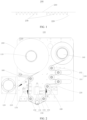
- the adhesive application apparatus 100 illustrated in this application uses a double-sided adhesive 200 as shown in FIG. 1 .
- the double-sided adhesive 200 includes first release paper 210, second release paper 220, and a plurality of adhesive strips 230.
- the plurality of adhesive strips 230 are spaced apart between the second release paper 220 and the first release paper 210, where the first release paper 210 detaches from the adhesive strip 230 more easily than the second release paper 220.
- the first release paper 210 and the second release paper 220 are anti-adhesive paper that prevents the prepreg from sticking and can protect the prepreg from contamination.
- the prepreg can be attached to the release paper, but not securely.
- the prepreg is the adhesive strip 230.
- the adhesive strip 230 can be attached to the release paper, but not securely.
- Two opposite surfaces of the adhesive strip 230 are adhesive, and the first release paper 210 and the second release paper 220 are disposed on the two adhesive surfaces of the adhesive strip 230 respectively, so as to isolate the adhesive strip 230 from the outside, thereby preventing the adhesive strip 230 from being attached to another object.
- the two adhesive surfaces of the adhesive strip 230 can be completely detached from the first release paper 210 and the second release paper 220.
- the first release paper 210 detaches from the adhesive strip 230 more easily than the second release paper 220, so that when the first release paper 210 and the second release paper 220 are stripped in two directions, the adhesive strip 230 stays attached to the surface of the second release paper 220 and is detached from the first release paper 210.
- every two adjacent adhesive strips 230 are evenly spaced apart.
- FIG. 2 shows the adhesive application apparatus 100 according to an embodiment of this application, configured to apply the double-sided adhesive 200 on an object surface.
- the object surface is a surface of an electrode plate roll in a battery cell. That is, the double-sided adhesive 200 is applied to the surface of an electrode plate roll.
- the adhesive application apparatus 100 may alternatively be used for applying the double-sided adhesive 200 to another obj ect.
- the adhesive application apparatus 100 includes an unwinding mechanism 110, a first winding mechanism 120, an adhesive application mechanism 130, and a second winding mechanism 140.
- the unwinding mechanism 110 is configured to dispose and unwind the double-sided adhesive 200.
- the first winding mechanism 120 is configured to peel off and wind the first release paper 210.
- the adhesive application mechanism 130 and the unwinding mechanism 110 jointly define a first path, and the first path is used to guide the adhesive strip 230 to move forward.
- the adhesive application mechanism 130 includes an adhesive application member 131 disposed on one side of the first path, where the adhesive application member 131 is configured to apply pressure from the one side of the first path to the double-sided adhesive 200, so as to attach the adhesive strip 230 to an object surface.
- the second winding mechanism 140 is configured to peel off and wind the second release paper 220.
- the unwinding mechanism 110 is configured to fasten the winded double-sided adhesive 200 and unwind the double-sided adhesive 200 by rotating.
- the unwinding mechanism 110 includes an unwinding wheel that can rotate around its own axis, and the unwinding wheel is used for setting the winded double-sided adhesive.
- the unwinding mechanism 110 may further be provided with a driving apparatus to drive the unwinding wheel to rotate.
- the driving apparatus may be an electrical motor, a heat engine, or the like.
- the first winding mechanism 120 is used for winding the first release paper 210.
- the first release paper 210 continuously strips from the adhesive strip 230, and finally is completely detached from the adhesive strip 230.
- the first winding mechanism 120 includes a winding wheel that can rotate around its own axis, and the winding wheel is used for setting the first release paper 210.
- the first winding mechanism 120 may be provided with a driving apparatus to drive the winding wheel to rotate.
- the driving apparatus may be an electrical motor, a heat engine, or the like.
- the adhesive application mechanism 130 is disposed on a downstream side of the first winding mechanism 120, and is configured to guide the second release paper 220 and the adhesive strip 230. In this way, the second release paper 220 and the adhesive strip 230 move along the first path, and the adhesive strip 230 is pressed to be attached to the object surface.
- the adhesive application mechanism 130 can attach the adhesive strip 230 to surfaces of the electrode plate rolls.
- "downstream" can be understood as a location or a direction, on a moving path of the adhesive strip 230, further away from the unwinding mechanism 110.
- the adhesive application member 131 is provided on one side of the first path, and can apply pressure from one side of the first path to the double-sided adhesive 200. In the implementation shown in FIG. 1 , the adhesive application member 131 can apply pressure to the adhesive strip 230 from one side, opposite the adhesive strip 230, of the second release paper 220, so that the adhesive strip 230 is attached to the object surface.
- the second winding mechanism 140 is disposed on a downstream side of the adhesive application mechanism 130.
- the second winding mechanism 140 is configured to wind the second release paper 220, and provides a pulling force for the second release paper 220 and the adhesive strip 230 to move along the first path.
- the second winding mechanism 140 includes a winding wheel that can rotate around its own axis, and the winding wheel is used for setting the second release paper 220.
- the second winding mechanism 140 may be provided with a driving apparatus to drive the winding wheel to rotate.
- the driving apparatus may be an electrical motor, a heat engine, or the like.
- downstream can be understood as a location or a direction, on a moving path of the adhesive strip 220, further away from the unwinding mechanism 110.
- the winded double-sided adhesive 200 is fastened to the unwinding mechanism 110, the first release paper 210 of the double-sided adhesive 200 is winded by the first winding mechanism 120, and the second release paper 220 passes through the adhesive application mechanism 130 along the first path and is finally winded by the second winding mechanism 140.
- the second winding mechanism 140 rotates and drives the second release paper 220 and the adhesive strip 230 to move along the first path.
- the adhesive application member 131 in the adhesive application mechanism 130 applies pressure to the adhesive strip 230 from one side, opposite the adhesive strip 230, of the second release paper 220, so that the adhesive strip 230 is attached to the object surface.
- the first release paper 210, the second release paper 220, and the adhesive strip 230 first move together along the first path.
- the first release paper 210 moves along the second path and is peeled off from the double-sided adhesive 200
- the second release paper 220 and the adhesive strip 230 continue to move along the first path.
- the second release paper 220 is winded by the second winding mechanism 140.
- the double-sided adhesive 200 with the first release paper 210 and the second release paper 220 is used, and the first winding mechanism 120 and the second winding mechanism 140 are configured to wind the first release paper 210 and the second release paper 220 respectively, so as to avoid the adhesive strip 230 between the first release paper 210 and the second release paper 220 from being attached to a surface of the adhesive application member 131 or another member and prevent adhesive application failure caused thereby.
- a plurality of adhesive strips 230 are spaced apart, and the adhesive application member 131 in the adhesive application mechanism 130 is configured to apply pressure from a side of the double-sided adhesive 200 to the double-sided adhesive 200, so that the adhesive strip 230 can be directly attached to the object surface without an adhesive cutting process or a cutter mechanism. This avoids the adhesive application failure due to adhesive cutting, thereby improving efficiency and success rate of adhesive application.
- a tension assembly 150 is disposed between the adhesive application mechanism 130 and the second winding mechanism 140, where the adhesive application mechanism 130, the second winding mechanism 140, and the tension assembly 150 form a second path.
- the second path is used to guide the second release paper 220 after being peeled to move forward, and the tension assembly 150 is able to extend or shorten length of the second path.
- the adhesive application mechanism 130, the tension assembly 150, and the second winding mechanism 140 are arranged in sequence and form a second path.
- the adhesive strip 230 detaches from the second release paper 220, the adhesive strip 230 is attached to the object surface, and the second release paper 220 continues to move along the second path.
- the tension assembly 150 is disposed between the adhesive application mechanism 130 and the second winding mechanism 140, so that the second release paper 220 can be kept stretched on the second path.
- the second winding mechanism 140 does not rotate, the length of the second path is extended, so that the second release paper 220 and the adhesive strip 230 at the adhesive application mechanism 130 move along the second path.
- the tension assembly 150 includes at least one position-adjustable movable wheel 151, where the movable wheel 151 participates in defining the second path.
- the length of the second path is extended or shortened.
- the movable wheel 151 can move relative to the adhesive application mechanism 130 and the second winding mechanism 140, so that the length of the second path can be adjusted by adjusting the position of the movable wheel 151.
- the movable wheel 151 can move horizontally, and the length of the second path is changed during such movement.
- a plurality of movable wheels 151 may be provided and all participate in defining the second path. In this case, when the position of any movable wheel 151 is adjusted, the length of the second path is extended or shortened. In the implementation shown in FIG. 2 , two movable wheels 151 are provided and both participate in defining the second path.
- the position-adjustable movable wheel 151 is disposed, and the position of the movable wheel 151 can be adjusted to change an arc of the second path, thereby changing a length of the second path between the adhesive application mechanism 130 and the second winding mechanism 140. In this way, the position of the movable wheel 151 is adjusted, so that the second release paper 220 and the adhesive strip 230 at the adhesive application mechanism 130 move along the second path.
- the tension assembly 150 further includes a fixed wheel 152 disposed in cooperation with the movable wheel 151.
- a gap is formed between the fixed wheel 152 and the movable wheel 151, the gap serves as a part of the second path, and the movable wheel 151 is able to move toward or away from the fixed wheel 152.
- the second release paper 220 passes through the fixed wheel 152 and the movable wheel 151 in sequence or passes through the fixed wheel 152 and the movable wheel 151 in sequence, so that the gap between the fixed wheel 152 and the movable wheel 151 forms a part of the second path.
- the gap between the movable wheel 151 and the fixed wheel 152 becomes smaller, and the length of the second path is shortened;
- the gap between the movable wheel 151 and the fixed wheel 152 becomes larger, and the length of the second path is extended.
- the fixed wheel 152 and the movable wheel 151 are disposed in cooperation, and the fixed wheel 152 and the movable wheel 151 may be disposed in a one-to-one correspondence.
- two movable wheels 151 and two fixed wheel 152 are provided, each movable wheel 151 and a corresponding fixed wheel 152 are spaced apart, so that when the movable wheel 151 moves, the gap between the movable wheel 151 and the corresponding fixed wheel 152 becomes larger or smaller, thereby extending or shortening the length of the second path.
- the fixed wheel 152 and the movable wheel 151 are spaced apart and may be different in quantity.
- one movable wheel 151 is disposed between two fixed wheels 152, or one fixed wheel 152 is disposed between two movable wheels 151.
- the fixed wheel 152 is disposed in cooperation with the movable wheel 151, so that when the movable wheel 151 moves relative to the fixed wheel 152, the gap between the movable wheel 151 and the fixed wheel 152 can be changed to change the length of the second path.
- the tension assembly 150 further includes a first driving member 153 (not shown in the figure).
- the first driving member 153 connects to the movable wheel 151, and the first driving member 153 is configured to drive the movable wheel 151 to move.
- the first driving member 153 is configured to provide kinetic energy for the movable wheel 151 to move, and may be a cylinder, an electric motor, a heat engine, or the like.
- the first driving member 153 is disposed to provide kinetic energy for the movable wheel 151, so as to drive the movable wheel 151 to move.
- a first guiding wheel 160 is disposed between the unwinding mechanism 110 and the first winding mechanism 120.
- the first winding mechanism 120 and the adhesive application mechanism 130 are disposed on different sides of the first guiding wheel 160.
- the first winding mechanism 120 and the first guiding wheel 160 jointly define a third path for guiding the first release paper 210 to move forward, and the first guiding wheel 160 and the adhesive application mechanism 130 jointly define part of the first path.
- the second guiding wheel 180 can define, together with the first winding mechanism 120, the third path that the first release paper 210 moves on, and can further define, together with the adhesive application mechanism 130, the first path that the second release paper 220 and the adhesive strip 230 move on.
- the first guiding wheel 160 is disposed to keep the first release paper 210, the adhesive strip 230, and the second release paper 220 stretched, so as to facilitate the adhesive application mechanism 130 in applying adhesives.
- a second guiding wheel 180 is disposed between the adhesive application mechanism 130 and the second winding mechanism 140.
- the adhesive application mechanism 130 and the second winding mechanism 140 are disposed on different sides of the second guiding wheel 180.
- the adhesive application mechanism 130, the second guiding wheel 180, the tension assembly 150, and the second winding mechanism 140 jointly define the second path.
- the second guiding wheel 180 is between the adhesive application mechanism 130 and the tension assembly 150.
- a detection apparatus 170 is disposed between the first winding mechanism 120 and the adhesive application mechanism 130, and is configured to detect whether any adhesive strip 230 is present on a surface of the second release paper 220.
- the detection apparatus 170 is configured to detect whether any adhesive strip 230 is present on a surface of the second release paper 220.
- a scenario in which no adhesive strip 230 is present on a surface of the second release paper 220 because an adhesive strip 230 is attached to the first release paper 210 when the first release paper 210 is detached from the adhesive strip 230 and the second release paper 220, can be detected. This avoids missed adhesive application due to absence of the adhesive strip 230.
- the detection apparatus 170 may be an optical detection mechanism, and can determine whether any adhesive strip 230 is present on the surface of the second release paper 220 based on different surface colors of the second release paper 220 and the adhesive strip 230.
- the adhesive application member 131 is configured to be able to move back and forth along a direction perpendicular to the adhesive strip 230.
- the adhesive application member 131 moves back and forth along the direction perpendicular to the adhesive strip 230, so that the adhesive application member 131 can apply perpendicular pressure to the adhesive strip 230 from a side, opposite the adhesive strip 230, of the second release paper 220, so that the adhesive strip 230 is attached to the object surface.
- the adhesive application member 131 is connected to the second driving member 134, and the second driving member 134 is configured to provide kinetic energy for the adhesive application member 131 to move back and forth perpendicular to the adhesive strip 230, where the second driving member 134 may be a cylinder, a heat engine, an electric motor, or the like.
- the adhesive application mechanism 130 further includes a first tension wheel 132 and a second tension wheel 133.
- the first tension wheel 132 and the second tension wheel 133 are respectively disposed on sides upstream and downstream of the adhesive application member 131, and the first tension wheel 132, the second tension wheel 133, and the adhesive application member 131 jointly define part of the first path.
- the first tension wheel 132 and the second tension wheel 133 are used to stretch the second release paper 220, so as to avoid displacement of the second release paper 220 and the adhesive strip 230 due to insecure placement during movement. In this way, the second release paper 220 and the adhesive strip 230 are driven to move when the tension assembly 150 is adjusting the length of the second path.
- this application provides the adhesive application apparatus 100 that uses the double-sided adhesive 200 shown in FIG. 1 .
- the adhesive application apparatus 100 includes the unwinding mechanism 110, the first winding mechanism 120, the adhesive application mechanism 130, the tension assembly 150, and the second winding mechanism 140.
- the first guiding wheel 160 and the first winding mechanism 120 jointly define a moving path of the first release paper 210, and the path is denoted as the third path.
- the first guiding wheel 160 and the adhesive application mechanism 130 jointly define a moving path of the second release paper 220 and the adhesive strip 230, and the path is denoted as the first path.
- the adhesive application mechanism 130, the tension assembly 150, and the second winding mechanism 140 jointly define a moving path of the second release paper 220 that is detached from the adhesive strip 230, and the path is denoted as the second path.
- the winded disposed double-sided adhesive 200 is fastened to the unwinding mechanism 110, the first release paper 210 of the double-sided adhesive 200 is winded by the first winding mechanism 120 along the third path, and the second release paper 220 and the adhesive strip 230 pass through the detection apparatus 170 along the first path, where whether any adhesive strip 230 is present on the surface of the second release paper 220 is detected, and reaches the adhesive application mechanism 130.
- the second release paper 220 and the adhesive strip 230 pass through the first tension wheel 132 and the adhesive application member 131 successively, the second release paper 220 and the adhesive strip 230 are separated at the adhesive application member 131, and the second release paper 220 that is separated from the adhesive strip 230 continues to pass through the tension assembly 150 along the second path and reaches the second winding mechanism 140.
- the second release paper 220 is stretched between the first tension wheel 132 and the second tension wheel 133, and the second driving member 134 drives the adhesive application member 131 to apply pressure to the adhesive strip 230 from one side, opposite the adhesive strip 230, of the second release paper 220.
- the second winding mechanism 140 stops rotating, the movable wheel 151 in the tension mechanism moves along a direction away from the fixed wheel 152. In this way, the second path is extended, driving the second release paper 220 and the adhesive strip 230 in the adhesive application mechanism 130 to move forward, and an adhesive is applied on the object surface.
- the second winding mechanism 140 continues rotating to wind the second release paper 220, and the movable wheel 151 is restored to an initial position, so as to prepare for the next adhesive application.
- This application further provides a battery production line, including the adhesive application apparatus 100 according to any one of the foregoing implementations, and the adhesive application apparatus 100 is configured to apply a double-sided adhesive 200 on a surface of electrode plates.
Landscapes
- Engineering & Computer Science (AREA)
- Manufacturing & Machinery (AREA)
- Chemical & Material Sciences (AREA)
- Chemical Kinetics & Catalysis (AREA)
- Electrochemistry (AREA)
- General Chemical & Material Sciences (AREA)
- Coating Apparatus (AREA)
- Adhesive Tape Dispensing Devices (AREA)
- Secondary Cells (AREA)
Applications Claiming Priority (1)
| Application Number | Priority Date | Filing Date | Title |
|---|---|---|---|
| CN202220855179.9U CN217496814U (zh) | 2022-04-14 | 2022-04-14 | 贴胶装置及具有该贴胶装置的电池生产线 |
Publications (2)
| Publication Number | Publication Date |
|---|---|
| EP4261143A1 true EP4261143A1 (de) | 2023-10-18 |
| EP4261143B1 EP4261143B1 (de) | 2025-02-12 |
Family
ID=83350663
Family Applications (1)
| Application Number | Title | Priority Date | Filing Date |
|---|---|---|---|
| EP23165798.2A Active EP4261143B1 (de) | 2022-04-14 | 2023-03-31 | Klebstoffauftragsvorrichtung und batterieproduktionslinie mit solch einer klebstoffauftragsvorrichtung |
Country Status (5)
| Country | Link |
|---|---|
| US (1) | US12272781B2 (de) |
| EP (1) | EP4261143B1 (de) |
| CN (1) | CN217496814U (de) |
| ES (1) | ES3027634T3 (de) |
| HU (1) | HUE071225T2 (de) |
Families Citing this family (3)
| Publication number | Priority date | Publication date | Assignee | Title |
|---|---|---|---|---|
| CN116081376A (zh) * | 2022-12-26 | 2023-05-09 | 昂华(上海)自动化工程股份有限公司 | 一种自动贴双面胶机 |
| CN115959512A (zh) * | 2023-02-15 | 2023-04-14 | 苏州盈科电子有限公司 | 背胶粘贴设备 |
| CN117594859B (zh) * | 2024-01-19 | 2024-07-23 | 宁德时代新能源科技股份有限公司 | 一种贴胶系统和贴胶方法 |
Citations (3)
| Publication number | Priority date | Publication date | Assignee | Title |
|---|---|---|---|---|
| US20050061426A1 (en) * | 2003-09-18 | 2005-03-24 | Michael Parker | Stacking apparatus and method for assembly of polymer batteries |
| EP2665657A1 (de) * | 2011-01-18 | 2013-11-27 | P.E. Labellers S.p.A. | Anordnung zum zuführen von etiketten und aufnehmen eines stützbandes in einer etikettiermaschine für vorgeklebte etiketten |
| CN209747650U (zh) * | 2019-04-16 | 2019-12-06 | 国机智骏汽车有限公司 | 一种新能源电池的自动贴胶装置 |
Family Cites Families (2)
| Publication number | Priority date | Publication date | Assignee | Title |
|---|---|---|---|---|
| CN108657864B (zh) | 2018-05-28 | 2024-02-20 | 深圳市赢合科技股份有限公司 | 一种自动贴双面胶装置 |
| CN214381607U (zh) * | 2020-11-30 | 2021-10-08 | 苏州赛腾菱欧智能科技有限公司 | 一种双面胶带贴附机构 |
-
2022
- 2022-04-14 CN CN202220855179.9U patent/CN217496814U/zh active Active
-
2023
- 2023-03-31 EP EP23165798.2A patent/EP4261143B1/de active Active
- 2023-03-31 ES ES23165798T patent/ES3027634T3/es active Active
- 2023-03-31 HU HUE23165798A patent/HUE071225T2/hu unknown
- 2023-04-11 US US18/298,381 patent/US12272781B2/en active Active
Patent Citations (3)
| Publication number | Priority date | Publication date | Assignee | Title |
|---|---|---|---|---|
| US20050061426A1 (en) * | 2003-09-18 | 2005-03-24 | Michael Parker | Stacking apparatus and method for assembly of polymer batteries |
| EP2665657A1 (de) * | 2011-01-18 | 2013-11-27 | P.E. Labellers S.p.A. | Anordnung zum zuführen von etiketten und aufnehmen eines stützbandes in einer etikettiermaschine für vorgeklebte etiketten |
| CN209747650U (zh) * | 2019-04-16 | 2019-12-06 | 国机智骏汽车有限公司 | 一种新能源电池的自动贴胶装置 |
Also Published As
| Publication number | Publication date |
|---|---|
| US12272781B2 (en) | 2025-04-08 |
| US20230335775A1 (en) | 2023-10-19 |
| HUE071225T2 (hu) | 2025-08-28 |
| ES3027634T3 (en) | 2025-06-16 |
| EP4261143B1 (de) | 2025-02-12 |
| CN217496814U (zh) | 2022-09-27 |
Similar Documents
| Publication | Publication Date | Title |
|---|---|---|
| US20230256464A1 (en) | Gas adsorption apparatus, end cap assembly, battery cell, battery, and electrical device | |
| EP4261143B1 (de) | Klebstoffauftragsvorrichtung und batterieproduktionslinie mit solch einer klebstoffauftragsvorrichtung | |
| JP6019137B2 (ja) | テープ付着自動化装置 | |
| US20240234785A1 (en) | Cell winding device and method | |
| CN114551949B (zh) | 五合一成型装置 | |
| US20250070114A1 (en) | Marking device and lamination manufacturing system | |
| CN118610546B (zh) | 贴胶装置以及电池生产线 | |
| CN108807841A (zh) | 一种贴胶装置 | |
| US20240162472A1 (en) | Winding Apparatus and Winding Method for Electrode Connection Film and Electrode Roll | |
| CN218987196U (zh) | 贴标装置和极片成型设备 | |
| CN111470355A (zh) | 贴胶设备 | |
| CN119429839A (zh) | 贴胶装置、贴胶系统及贴胶方法 | |
| CN117226904A (zh) | 间歇式复合带及制备方法、转移带及制备装置和方法 | |
| CN223973521U (zh) | 一种基于锂离子电池pack装配线绝缘膜贴膜装置 | |
| CN210854647U (zh) | 单面陶瓷隔膜分切机 | |
| CN223212733U (zh) | 一种贴标签装置 | |
| CN220282944U (zh) | 一种换卷装置、电芯卷绕设备 | |
| KR102888609B1 (ko) | 전지의 제조 방법 | |
| CN217719710U (zh) | 胶带换卷装置、贴胶设备及电池生产系统 | |
| CN215159561U (zh) | 一种自动收离型纸装置 | |
| US20250282569A1 (en) | Adhesive tape applying device, adhesive tape applying method and battery production line | |
| CN221915022U (zh) | 供胶装置、贴胶设备以及电池生产线 | |
| KR20240086067A (ko) | 테이프 스플라이싱 유닛을 포함하는 이차전지 셀을 위한 테이프 공급 장치 | |
| CN221955447U (zh) | 料带换卷机构及叠片设备 | |
| CN223947288U (zh) | 极耳堆叠裁切机 |
Legal Events
| Date | Code | Title | Description |
|---|---|---|---|
| PUAI | Public reference made under article 153(3) epc to a published international application that has entered the european phase |
Free format text: ORIGINAL CODE: 0009012 |
|
| STAA | Information on the status of an ep patent application or granted ep patent |
Free format text: STATUS: THE APPLICATION HAS BEEN PUBLISHED |
|
| AK | Designated contracting states |
Kind code of ref document: A1 Designated state(s): AL AT BE BG CH CY CZ DE DK EE ES FI FR GB GR HR HU IE IS IT LI LT LU LV MC ME MK MT NL NO PL PT RO RS SE SI SK SM TR |
|
| STAA | Information on the status of an ep patent application or granted ep patent |
Free format text: STATUS: REQUEST FOR EXAMINATION WAS MADE |
|
| 17P | Request for examination filed |
Effective date: 20231031 |
|
| RBV | Designated contracting states (corrected) |
Designated state(s): AL AT BE BG CH CY CZ DE DK EE ES FI FR GB GR HR HU IE IS IT LI LT LU LV MC ME MK MT NL NO PL PT RO RS SE SI SK SM TR |
|
| RAP1 | Party data changed (applicant data changed or rights of an application transferred) |
Owner name: CONTEMPORARY AMPEREX TECHNOLOGY(HONG KONG) LIMITED |
|
| GRAP | Despatch of communication of intention to grant a patent |
Free format text: ORIGINAL CODE: EPIDOSNIGR1 |
|
| STAA | Information on the status of an ep patent application or granted ep patent |
Free format text: STATUS: GRANT OF PATENT IS INTENDED |
|
| INTG | Intention to grant announced |
Effective date: 20241125 |
|
| GRAS | Grant fee paid |
Free format text: ORIGINAL CODE: EPIDOSNIGR3 |
|
| GRAA | (expected) grant |
Free format text: ORIGINAL CODE: 0009210 |
|
| STAA | Information on the status of an ep patent application or granted ep patent |
Free format text: STATUS: THE PATENT HAS BEEN GRANTED |
|
| AK | Designated contracting states |
Kind code of ref document: B1 Designated state(s): AL AT BE BG CH CY CZ DE DK EE ES FI FR GB GR HR HU IE IS IT LI LT LU LV MC ME MK MT NL NO PL PT RO RS SE SI SK SM TR |
|
| REG | Reference to a national code |
Ref country code: GB Ref legal event code: FG4D |
|
| REG | Reference to a national code |
Ref country code: CH Ref legal event code: EP |
|
| P01 | Opt-out of the competence of the unified patent court (upc) registered |
Free format text: CASE NUMBER: APP_1314/2025 Effective date: 20250109 |
|
| REG | Reference to a national code |
Ref country code: DE Ref legal event code: R096 Ref document number: 602023001965 Country of ref document: DE |
|
| REG | Reference to a national code |
Ref country code: IE Ref legal event code: FG4D |
|
| REG | Reference to a national code |
Ref country code: ES Ref legal event code: FG2A Ref document number: 3027634 Country of ref document: ES Kind code of ref document: T3 Effective date: 20250616 |
|
| REG | Reference to a national code |
Ref country code: NL Ref legal event code: MP Effective date: 20250212 |
|
| PG25 | Lapsed in a contracting state [announced via postgrant information from national office to epo] |
Ref country code: RS Free format text: LAPSE BECAUSE OF FAILURE TO SUBMIT A TRANSLATION OF THE DESCRIPTION OR TO PAY THE FEE WITHIN THE PRESCRIBED TIME-LIMIT Effective date: 20250512 |
|
| PG25 | Lapsed in a contracting state [announced via postgrant information from national office to epo] |
Ref country code: FI Free format text: LAPSE BECAUSE OF FAILURE TO SUBMIT A TRANSLATION OF THE DESCRIPTION OR TO PAY THE FEE WITHIN THE PRESCRIBED TIME-LIMIT Effective date: 20250212 |
|
| PG25 | Lapsed in a contracting state [announced via postgrant information from national office to epo] |
Ref country code: PL Free format text: LAPSE BECAUSE OF FAILURE TO SUBMIT A TRANSLATION OF THE DESCRIPTION OR TO PAY THE FEE WITHIN THE PRESCRIBED TIME-LIMIT Effective date: 20250212 |
|
| PGFP | Annual fee paid to national office [announced via postgrant information from national office to epo] |
Ref country code: ES Payment date: 20250401 Year of fee payment: 3 |
|
| REG | Reference to a national code |
Ref country code: LT Ref legal event code: MG9D |
|
| PG25 | Lapsed in a contracting state [announced via postgrant information from national office to epo] |
Ref country code: IS Free format text: LAPSE BECAUSE OF FAILURE TO SUBMIT A TRANSLATION OF THE DESCRIPTION OR TO PAY THE FEE WITHIN THE PRESCRIBED TIME-LIMIT Effective date: 20250612 Ref country code: NO Free format text: LAPSE BECAUSE OF FAILURE TO SUBMIT A TRANSLATION OF THE DESCRIPTION OR TO PAY THE FEE WITHIN THE PRESCRIBED TIME-LIMIT Effective date: 20250512 |
|
| PG25 | Lapsed in a contracting state [announced via postgrant information from national office to epo] |
Ref country code: NL Free format text: LAPSE BECAUSE OF FAILURE TO SUBMIT A TRANSLATION OF THE DESCRIPTION OR TO PAY THE FEE WITHIN THE PRESCRIBED TIME-LIMIT Effective date: 20250212 |
|
| PG25 | Lapsed in a contracting state [announced via postgrant information from national office to epo] |
Ref country code: HR Free format text: LAPSE BECAUSE OF FAILURE TO SUBMIT A TRANSLATION OF THE DESCRIPTION OR TO PAY THE FEE WITHIN THE PRESCRIBED TIME-LIMIT Effective date: 20250212 |
|
| PG25 | Lapsed in a contracting state [announced via postgrant information from national office to epo] |
Ref country code: PT Free format text: LAPSE BECAUSE OF FAILURE TO SUBMIT A TRANSLATION OF THE DESCRIPTION OR TO PAY THE FEE WITHIN THE PRESCRIBED TIME-LIMIT Effective date: 20250612 Ref country code: LV Free format text: LAPSE BECAUSE OF FAILURE TO SUBMIT A TRANSLATION OF THE DESCRIPTION OR TO PAY THE FEE WITHIN THE PRESCRIBED TIME-LIMIT Effective date: 20250212 |
|
| PG25 | Lapsed in a contracting state [announced via postgrant information from national office to epo] |
Ref country code: BG Free format text: LAPSE BECAUSE OF FAILURE TO SUBMIT A TRANSLATION OF THE DESCRIPTION OR TO PAY THE FEE WITHIN THE PRESCRIBED TIME-LIMIT Effective date: 20250212 Ref country code: GR Free format text: LAPSE BECAUSE OF FAILURE TO SUBMIT A TRANSLATION OF THE DESCRIPTION OR TO PAY THE FEE WITHIN THE PRESCRIBED TIME-LIMIT Effective date: 20250513 |
|
| REG | Reference to a national code |
Ref country code: AT Ref legal event code: MK05 Ref document number: 1765884 Country of ref document: AT Kind code of ref document: T Effective date: 20250212 |
|
| REG | Reference to a national code |
Ref country code: HU Ref legal event code: AG4A Ref document number: E071225 Country of ref document: HU |
|
| PG25 | Lapsed in a contracting state [announced via postgrant information from national office to epo] |
Ref country code: SE Free format text: LAPSE BECAUSE OF FAILURE TO SUBMIT A TRANSLATION OF THE DESCRIPTION OR TO PAY THE FEE WITHIN THE PRESCRIBED TIME-LIMIT Effective date: 20250212 |
|
| PG25 | Lapsed in a contracting state [announced via postgrant information from national office to epo] |
Ref country code: SM Free format text: LAPSE BECAUSE OF FAILURE TO SUBMIT A TRANSLATION OF THE DESCRIPTION OR TO PAY THE FEE WITHIN THE PRESCRIBED TIME-LIMIT Effective date: 20250212 |
|
| PG25 | Lapsed in a contracting state [announced via postgrant information from national office to epo] |
Ref country code: DK Free format text: LAPSE BECAUSE OF FAILURE TO SUBMIT A TRANSLATION OF THE DESCRIPTION OR TO PAY THE FEE WITHIN THE PRESCRIBED TIME-LIMIT Effective date: 20250212 |
|
| PG25 | Lapsed in a contracting state [announced via postgrant information from national office to epo] |
Ref country code: IT Free format text: LAPSE BECAUSE OF FAILURE TO SUBMIT A TRANSLATION OF THE DESCRIPTION OR TO PAY THE FEE WITHIN THE PRESCRIBED TIME-LIMIT Effective date: 20250212 |
|
| PG25 | Lapsed in a contracting state [announced via postgrant information from national office to epo] |
Ref country code: AT Free format text: LAPSE BECAUSE OF FAILURE TO SUBMIT A TRANSLATION OF THE DESCRIPTION OR TO PAY THE FEE WITHIN THE PRESCRIBED TIME-LIMIT Effective date: 20250212 |
|
| PG25 | Lapsed in a contracting state [announced via postgrant information from national office to epo] |
Ref country code: EE Free format text: LAPSE BECAUSE OF FAILURE TO SUBMIT A TRANSLATION OF THE DESCRIPTION OR TO PAY THE FEE WITHIN THE PRESCRIBED TIME-LIMIT Effective date: 20250212 Ref country code: CZ Free format text: LAPSE BECAUSE OF FAILURE TO SUBMIT A TRANSLATION OF THE DESCRIPTION OR TO PAY THE FEE WITHIN THE PRESCRIBED TIME-LIMIT Effective date: 20250212 |
|
| PG25 | Lapsed in a contracting state [announced via postgrant information from national office to epo] |
Ref country code: RO Free format text: LAPSE BECAUSE OF FAILURE TO SUBMIT A TRANSLATION OF THE DESCRIPTION OR TO PAY THE FEE WITHIN THE PRESCRIBED TIME-LIMIT Effective date: 20250212 |
|
| PG25 | Lapsed in a contracting state [announced via postgrant information from national office to epo] |
Ref country code: SK Free format text: LAPSE BECAUSE OF FAILURE TO SUBMIT A TRANSLATION OF THE DESCRIPTION OR TO PAY THE FEE WITHIN THE PRESCRIBED TIME-LIMIT Effective date: 20250212 |
|
| REG | Reference to a national code |
Ref country code: DE Ref legal event code: R097 Ref document number: 602023001965 Country of ref document: DE |
|
| PG25 | Lapsed in a contracting state [announced via postgrant information from national office to epo] |
Ref country code: LU Free format text: LAPSE BECAUSE OF NON-PAYMENT OF DUE FEES Effective date: 20250331 |
|
| REG | Reference to a national code |
Ref country code: BE Ref legal event code: MM Effective date: 20250331 |
|
| PLBE | No opposition filed within time limit |
Free format text: ORIGINAL CODE: 0009261 |
|
| STAA | Information on the status of an ep patent application or granted ep patent |
Free format text: STATUS: NO OPPOSITION FILED WITHIN TIME LIMIT |
|
| PG25 | Lapsed in a contracting state [announced via postgrant information from national office to epo] |
Ref country code: MC Free format text: LAPSE BECAUSE OF FAILURE TO SUBMIT A TRANSLATION OF THE DESCRIPTION OR TO PAY THE FEE WITHIN THE PRESCRIBED TIME-LIMIT Effective date: 20250212 |
|
| PG25 | Lapsed in a contracting state [announced via postgrant information from national office to epo] |
Ref country code: BE Free format text: LAPSE BECAUSE OF NON-PAYMENT OF DUE FEES Effective date: 20250331 |
|
| PG25 | Lapsed in a contracting state [announced via postgrant information from national office to epo] |
Ref country code: IE Free format text: LAPSE BECAUSE OF NON-PAYMENT OF DUE FEES Effective date: 20250331 |
|
| 26N | No opposition filed |
Effective date: 20251113 |
|
| PGFP | Annual fee paid to national office [announced via postgrant information from national office to epo] |
Ref country code: DE Payment date: 20260324 Year of fee payment: 4 |
|
| PGFP | Annual fee paid to national office [announced via postgrant information from national office to epo] |
Ref country code: FR Payment date: 20260330 Year of fee payment: 4 |