EP4261176B1 - Mécanisme télescopique de flèche à sections multiples monocylindrique, flèche et grue - Google Patents
Mécanisme télescopique de flèche à sections multiples monocylindrique, flèche et grue Download PDFInfo
- Publication number
- EP4261176B1 EP4261176B1 EP22808574.2A EP22808574A EP4261176B1 EP 4261176 B1 EP4261176 B1 EP 4261176B1 EP 22808574 A EP22808574 A EP 22808574A EP 4261176 B1 EP4261176 B1 EP 4261176B1
- Authority
- EP
- European Patent Office
- Prior art keywords
- arm
- section
- turning structure
- section arm
- telescopic
- Prior art date
- Legal status (The legal status is an assumption and is not a legal conclusion. Google has not performed a legal analysis and makes no representation as to the accuracy of the status listed.)
- Active
Links
Images
Classifications
-
- B—PERFORMING OPERATIONS; TRANSPORTING
- B66—HOISTING; LIFTING; HAULING
- B66C—CRANES; LOAD-ENGAGING ELEMENTS OR DEVICES FOR CRANES, CAPSTANS, WINCHES, OR TACKLES
- B66C23/00—Cranes comprising essentially a beam, boom, or triangular structure acting as a cantilever and mounted for translatory of swinging movements in vertical or horizontal planes or a combination of such movements, e.g. jib-cranes, derricks, tower cranes
- B66C23/62—Constructional features or details
- B66C23/64—Jibs
- B66C23/70—Jibs constructed of sections adapted to be assembled to form jibs or various lengths
- B66C23/701—Jibs constructed of sections adapted to be assembled to form jibs or various lengths telescopic
-
- B—PERFORMING OPERATIONS; TRANSPORTING
- B66—HOISTING; LIFTING; HAULING
- B66C—CRANES; LOAD-ENGAGING ELEMENTS OR DEVICES FOR CRANES, CAPSTANS, WINCHES, OR TACKLES
- B66C23/00—Cranes comprising essentially a beam, boom, or triangular structure acting as a cantilever and mounted for translatory of swinging movements in vertical or horizontal planes or a combination of such movements, e.g. jib-cranes, derricks, tower cranes
- B66C23/62—Constructional features or details
- B66C23/64—Jibs
- B66C23/70—Jibs constructed of sections adapted to be assembled to form jibs or various lengths
- B66C23/701—Jibs constructed of sections adapted to be assembled to form jibs or various lengths telescopic
- B66C23/703—Jibs constructed of sections adapted to be assembled to form jibs or various lengths telescopic telescoped by flexible elements, e.g. cables, chains or bands
-
- B—PERFORMING OPERATIONS; TRANSPORTING
- B66—HOISTING; LIFTING; HAULING
- B66C—CRANES; LOAD-ENGAGING ELEMENTS OR DEVICES FOR CRANES, CAPSTANS, WINCHES, OR TACKLES
- B66C23/00—Cranes comprising essentially a beam, boom, or triangular structure acting as a cantilever and mounted for translatory of swinging movements in vertical or horizontal planes or a combination of such movements, e.g. jib-cranes, derricks, tower cranes
- B66C23/62—Constructional features or details
- B66C23/64—Jibs
- B66C23/70—Jibs constructed of sections adapted to be assembled to form jibs or various lengths
- B66C23/701—Jibs constructed of sections adapted to be assembled to form jibs or various lengths telescopic
- B66C23/705—Jibs constructed of sections adapted to be assembled to form jibs or various lengths telescopic telescoped by hydraulic jacks
-
- Y—GENERAL TAGGING OF NEW TECHNOLOGICAL DEVELOPMENTS; GENERAL TAGGING OF CROSS-SECTIONAL TECHNOLOGIES SPANNING OVER SEVERAL SECTIONS OF THE IPC; TECHNICAL SUBJECTS COVERED BY FORMER USPC CROSS-REFERENCE ART COLLECTIONS [XRACs] AND DIGESTS
- Y02—TECHNOLOGIES OR APPLICATIONS FOR MITIGATION OR ADAPTATION AGAINST CLIMATE CHANGE
- Y02A—TECHNOLOGIES FOR ADAPTATION TO CLIMATE CHANGE
- Y02A20/00—Water conservation; Efficient water supply; Efficient water use
- Y02A20/20—Controlling water pollution; Waste water treatment
- Y02A20/204—Keeping clear the surface of open water from oil spills
Definitions
- the present invention relates to the mechanical engineering technical field, and specifically to a telescopic device with single cylinder and multiple section arms, a crane arm and a crane.
- arm body telescopic devices used for vehicle cranes.
- the first type several external or internal telescopic oil cylinders are provided outside or inside the arm body to push the telescopic arm body to move.
- Such device is relatively suitable for folding arm lorry cranes, but is not suitable for large-tonnage straight-arm lorry cranes having a telescopic arm with more than three sections due to mounting space, arm body length, self weight or other limiting reasons.
- two or three internal telescopic oil cylinders and a rope arranging mechanism are provided to drive several arm bodies to extend or retract in the following sequence: the first section extends first or the first and second sections of the arm body extend in sequence first, and then the subsequent sections of the arm body extend or retract synchronously.
- Such telescopic arm needs two or three internal telescopic oil cylinders, thus resulting in a larger section size of the jib arm body, a complicated internal structure, a large self weight of the jib assembly, fast attenuation for the loading ability of the crane, and a high cost.
- the telescopic arm body can extend or retract only in sequence during operation and it is difficult for a plurality of section arms to extend or retract synchronously, causing low operation efficiency of craning operation of the vehicle crane, a high cost due to multiple oil cylinders, and a high risk for leakage.
- CN 201433061Y discloses a telescopic device with a single cylinder and multiple section arms according to the preamble of claim 1.
- CN 206751235U a telescopic mechanism having five arms, including first section arm, second festival arm, third festival arm, fourth festival arm, pentamer arm, flexible hydro -cylinder and a wire rope, first pulley, the 2nd wire rope, second pulley, the 3rd wire rope, third pulley, fourth wire rope, fourth pulley, the 5th wire rope, the 5th pulley, the 6th wire rope, the 6th pulley, first section arm is connected with fixed external device, first section arm, second festival arm, third festival arm, fourth festival arm and pentamer arm are the box structure, and together nested in proper order, flexible hydro -cylinder embeds in the cavity, the piston rod of flexible hydro -cylinder is connected with first section arm, the cylinder of flexible hydro -cylinder is connected with second festival arm.
- the present invention aims to solve at least one of the above technical problems.
- a telescopic device with single cylinder and multiple section arms comprises: a third extension rope, a third retraction rope, a telescopic mechanism, a first section arm, as well as a second section arm and a third section arm which are nested in sequence within the first section arm, the telescopic mechanism has a fixed end connected with the first section arm and a movable end provided with a first turning structure, the second section arm is connected with the movable end of the telescopic mechanism and is further provided with a second turning structure, the third extension rope has one end connected with the first section arm and the other end connected with the third section arm after passing around a top portion of the first turning structure, the third retraction rope has one end connected with the first section arm and the other end connected with the third section arm after passing around a bottom portion of the second turning structure.
- the telescopic device with single cylinder and multiple section arms comprises but is not limited to the following beneficial effects compared with the prior art:
- the first section arm is the basic arm which is generally stationary in operation.
- the movable end of the telescopic mechanism is moved with respect to the first section arm.
- the second section arm is connected with the movable end of the telescopic mechanism such that when the telescopic mechanism performs extending or retracting, the second section arm is caused to extend or retract.
- the second section arm extends for 1S
- the first turning structure extends for 1S with respect to the first section arm
- the third section arm is caused to extend for 2S with respect to the first section arm, that is, the third section arm extends for 1S with respect to the second section arm
- synchronous extension of the three section arms is achieved with a single cylinder, and the relative extension amount of adjacent two section arms is same.
- the third section arm is caused to retract for 2S with respect to the first section arm, that is, the third section arm retracts for 1S with respect to the second section arm, synchronous retraction of the three section arms is achieved with a single cylinder, and the relative retraction amount of adjacent two section arms is same, thus the operation efficiency is improved.
- the telescopic mechanism is a telescopic cylinder, a cylinder body of the telescopic cylinder is disposed upward, wherein a piston rod of the telescopic cylinder is the fixed end of the telescopic mechanism and the cylinder body of the telescopic cylinder is the movable end of the telescopic mechanism.
- a bottom end of the piston rod of the telescopic cylinder is connected with an arm rear of the first section arm
- a bottom end of the cylinder body of the telescopic cylinder is connected with an arm rear of the second section arm
- the first turning structure is disposed at a top end of the cylinder body of the telescopic cylinder
- the second turning structure is disposed at the arm rear of the second section arm
- the third extension rope has one end connected with the arm rear of the first section arm and the other end connected with an arm rear of the third section arm
- the third retraction rope has one end connected with an arm head the first section arm and the other end connected with the arm rear of the third section arm.
- the telescopic device with single cylinder and multiple section arms further comprises a fourth extension rope, a fourth retraction rope, and a fourth section arm nested within the third section arm
- the third section arm is provided at its arm head with a third turning structure
- the fourth section arm is provided at its arm rear with a fourth turning structure
- the fourth extension rope has one end connected with the arm rear of the first section arm and the other end connected with an arm head of the third section arm after passing around the third turning structure and the fourth turning structure in sequence
- the third section arm is provide at its arm rear with a fifth turning structure
- the fourth retraction rope has one end connected with the arm rear of the fourth section arm and the other end connected with an end of the telescopic cylinder far away from the arm rear of the first section arm after passing around the fifth turning structure.
- the third turning structure, the fourth turning structure and the fifth turning structure are pulleys.
- the telescopic device with single cylinder and multiple section arms further comprises a fourth extension rope, a fourth retraction rope, a fifth extension rope as well as a fourth section arm and a fifth section arm which are nested in sequence within the third section arm, the third section arm is provided at its arm head with a third turning structure, the fourth section arm is provided at its arm rear with a fourth turning structure, the fourth extension rope has one end connected with the arm rear of the first section arm and the other end connected with an arm head of the third section arm after passing around the third turning structure and the fourth turning structure in sequence, the third section arm is provided at its arm rear with a fifth turning structure;
- the third turning structure, the fourth turning structure, the fifth turning structure, the sixth turning structure, the seventh turning structure and the eighth turning structure are pulleys.
- the arm rear of either of the second section arm and the third section arm is provided with a rope hole.
- a crane arm comprising the telescopic device with single cylinder and multiple section arms as described above.
- a crane is provided in the present invention, comprising the crane arm as described above.
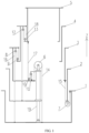
- FIG 1 is a structural diagram of a telescopic device with single cylinder and multiple section arms of an embodiment of the present invention.
- the Z axis in the figures represents a vertical direction, showing upper and lower positions, with the positive direction of the Z axis (i.e. the direction indicated by the arrow of the Z axis) representing "upper” and the negative direction of the Z axis (i.e. the direction opposite to the positive direction of the Z axis) representing "lower".
- a telescopic device with single cylinder and multiple section arms of an embodiment of the present invention comprises: a third extension rope 14, a third retraction rope 15, a telescopic mechanism 19, a first section arm 1, as well as a second section arm 2 and a third section arm 3 that are nested in sequence within the first section arm 1,
- the telescopic mechanism 19 has a fixed end connected with the first section arm 1 and a movable end provided with a first turning structure 6,
- the second section arm 2 is connected with the movable end of the telescopic mechanism 19 and is further provided with a second turning structure 7,
- the third extension rope 14 has one end connected with the first section arm 1 and the other end connected with the third section arm 3 after passing around a top portion of the first turning structure 6,
- the third retraction rope 15 has one end connected with the first section arm 1 and the other end connected with the third section arm 3 after passing around a bottom portion of the second turning structure 7.
- the first section arm 1 is the basic arm which is generally stationary in operation.
- the telescopic mechanism 19 has one end connected with the arm rear of the first section arm 1, and when the telescopic mechanism 19 performs extending or retracting, the movable end of the telescopic mechanism 19 is moved with respect to the first section arm 1.
- the second section arm 2 is connected with the movable end of the telescopic mechanism 19 such that when the telescopic mechanism 19 performs extending or retracting, the second section arm 2 is caused to extend or retract.
- the third section arm 3 is caused to retract for 2S with respect to the first section arm 1, that is, the third section arm 3 retracts for 1S with respect to the second section arm 2, synchronous retraction of the three section arms with a single cylinder is achieved, and the relative retraction amount of adjacent two section arms is same, thus the operation efficiency is improved.
- the telescopic mechanism 19 is a telescopic cylinder, a cylinder body of the telescopic cylinder is disposed upward, wherein a piston rod of the telescopic cylinder is the fixed end of the telescopic mechanism 19 and the cylinder body of the telescopic cylinder is the movable end of the telescopic mechanism 19.
- the rod head of the telescopic cylinder is the outer end of the piston rod, i.e. the bottom end of the piston rod, and the end of the cylinder body of the telescopic cylinder adjacent to the rod head is the bottom end of the cylinder body.
- the arm rear of the second section arm 2 can be overlapped with the first section arm in the maximum degree, so the maximum range of extending and retracting of the second section arm 2 can be achieved.
- the telescopic cylinder may be an oil cylinder.
- the telescopic cylinder When a rodless cavity of the cylinder body is filled with oil, the telescopic cylinder is extended, and when a rod cavity of the cylinder body is filled with oil, the telescopic cylinder is retracted.
- first turning structure 6 and the second turning structure 7 are pulleys.
- the first turning structure 6 and the second turning structure 7 are pulleys, thus reducing friction force during movement of the respective ropes, increasing service lives of the third extension rope 14 and the third retraction rope 15, and also lowering the load of the telescopic cylinder.
- a bottom end of the piston rod of the telescopic cylinder is connected with an arm rear of the first section arm 1
- a bottom end of the cylinder body of the telescopic cylinder is connected with an arm rear of the second section arm 2
- the first turning structure 6 is disposed at a top end of the cylinder body of the telescopic cylinder
- the second turning structure 7 is disposed at the arm rear of the second section arm 2
- the third extension rope 14 has one end connected with the arm rear of the first section arm 1 and the other end connected with an arm rear of the third section arm 3
- the third retraction rope 15 has one end connected with an arm head the first section arm 1 and the other end connected with the arm rear of the third section arm 3.
- the arm rear refers to the end of the respective section arm at the negative portion of the Z axis, i.e. the bottom end of the section arm
- the arm head refers to the end of the respective section arm at the positive portion of the Z axis, i.e. the top end of the section arm.
- the ends of the ropes are connected to the arm rear(s) or arm head(s) of the respective section arms, and the bottom end of the cylinder body of the telescopic cylinder is connected with the arm rear of the second section arm 2.
- the telescopic device with single cylinder and multiple section arms further comprises: a fourth extension rope 16, a fourth retraction rope 17, and a fourth section arm 4 nested within the third section arm 3, the third section arm 3 is provided at its arm head with a third turning structure 8, the fourth section arm 4 is provided at its arm rear with a fourth turning structure 9, the fourth extension rope 16 has one end connected with the arm rear of the first section arm 1 and the other end connected with an arm head of the third section arm 3 after passing around the third turning structure 8 and the fourth turning structure 9 in sequence, the third section arm 3 is provide at its arm rear with a fifth turning structure 10, the fourth retraction rope 17 has one end connected with the arm rear of the fourth section arm 4 and the other end connected with an end of the telescopic cylinder far away from the arm rear of the first section arm 1 after passing around the fifth turning structure 10.
- the third section arm 3 is caused to extend for 2S with respect to the first section arm 1, that is, the third section arm 3 extends for 1S with respect to the second section arm 2.
- the fourth section arm 4 is pulled to extend for 3S with respect to the first section arm 1, that is, the fourth section arm 4 is pulled to extend for 1S with respect to the third section arm 3, synchronous extension of the four section arms is achieved with a single cylinder, and the relative extension amount of adjacent two section arms is same.
- the third section arm 3 is caused to retract for 2S with respect to the first section arm 1, that is, the third section arm 3 retracts for 1S with respect to the second section arm 2.
- the fourth section arm 4 is caused to retract for 3S with respect to the first section arm 1, synchronous retraction of the four section arms is achieved with a single cylinder, and the relative retraction amount of adjacent two section arms is same.
- the third turning structure 8, the fourth turning structure 9 and the fifth turning structure 10 are pulleys.
- the third turning structure 8, the fourth turning structure 9 and the fifth turning structure 10 are pulleys, thus reducing friction force during movement of the respective ropes, increasing service lives of the fourth extension rope 16 and the fourth retraction rope 17, and also lowering the load of the telescopic cylinder.
- the telescopic device with single cylinder and multiple section arms further comprises a fourth extension rope 16, a fourth retraction rope 17, a fifth extension rope 18 as well as a fourth section arm 4 and a fifth section arm 5 which are nested in sequence within the third section arm 3,
- the third section arm 3 is provided at its arm head with a third turning structure 8
- the fourth section arm 4 is provided at its arm rear with a fourth turning structure 9
- the fourth extension rope 16 has one end connected with the arm rear of the first section arm 1 and the other end connected with an arm head of the third section arm 3 after passing around the third turning structure 8 and the fourth turning structure 9 in sequence
- the third section arm 3 is provided at its arm rear with a fifth turning structure 10.
- the telescopic cylinder is provided, at its end far away from the arm rear of the first section arm 1, with a sixth turning structure 11, the fourth section arm 4 is provided at its arm head with a seventh turning structure 12, the fifth section arm 5 is provided at its arm rear with an eighth turning structure 13, the fifth extension rope 18 has one end connected with the arm rear of the second section arm 2 and the other end connected with the arm head of the fourth section arm 4 after passing around the seventh turning structure 12 and the eighth turning structure 13 in sequence.
- the fourth retraction rope 17 has one end connected with the arm rear of the fifth section arm 5 and the other end connected with the arm rear of the third section arm 3 after passing around the fifth turning structure 10 and the sixth turning structure 11 in sequence.
- the sixth turning structure 11 is further provided.
- the sixth turning structure 11 is fixed to the top end of the telescopic cylinder.
- the fourth retraction rope 17 has one end connected with the arm rear of the fifth section arm 5 and the other end connected with the arm rear of the third section arm 3 after passing around the fifth turning structure 10 and the sixth turning structure 11 in sequence.
- the fifth section arm 5 is caused to retract for 4S with respect to the first section arm 1
- the fifth section arm 5 retracts for 4S with respect to the first section arm 1
- the fourth section arm 4 is caused to retract for 3S with respect to the first section arm 1, achieving synchronous retraction of the five section arms with a single cylinder.
- the pulling force directly on the fourth section arm 4 comes from the fourth extension rope 16 extending along both sides of the fourth turning mechanism.
- the load on the fourth extension rope 16 is smaller, while ensuring that the extension amount of the fourth section arm 4 with respect to the third section arm 3 is consistent with that of the telescopic cylinder.
- the third turning structure 8, the fourth turning structure 9, the fifth turning structure 10, the sixth turning structure 11, seventh turning structure 12 and the eighth turning structure 13 are pulleys.
- all turning structures are pulleys, thus reducing friction force during movement of the respective ropes, increasing service lives of the ropes, and also lowering the load of the telescopic cylinder.
- the arm rear of either of the second section arm 2 and the third section arm 3 is provided with a rope hole.
- the rope holes are provided for the respective ropes to pass through, avoiding an overlong path of the rope(s).
- a crane arm comprises the telescopic device with single cylinder and multiple section arms as described above.
- a crane comprises the crane arm as described above.
- first and second are used for purpose of description only, and can not be understood as indicating or implying relative importance or implicitly showing the number of the indicated technical feature(s). Therefore, the features defined with “first” and “second” may explicitly or implicitly comprise at least one such feature.
Landscapes
- Engineering & Computer Science (AREA)
- Mechanical Engineering (AREA)
- Jib Cranes (AREA)
- Steering-Linkage Mechanisms And Four-Wheel Steering (AREA)
Claims (6)
- Un dispositif télescopique à un seul cylindre et bras de section multiples, comprenant :un troisième câble d'extension (14), un troisième câble de rétraction (15), un mécanisme télescopique (19), un premier bras de section (1), ainsi qu'un deuxième bras de section (2) et un troisième bras de section (3) qui sont emboîtés en séquence au sein du premier bras de section (1), le mécanisme télescopique (19) ayant une extrémité fixe reliée au premier bras de section (1) et une extrémité mobile pourvue d'une première structure tournante (6), le deuxième bras de section (2) étant relié à l'extrémité mobile du mécanisme télescopique (19) et étant en outre pourvu d'une deuxième structure tournante (7), le troisième câble d'extension (14) ayant une extrémité reliée au premier bras de section (1) et l'autre extrémité reliée au troisième bras de section (3) après être passée autour d'une portion supérieure de la première structure tournante (6), le troisième câble de rétraction (15) ayant une extrémité reliée au premier bras de section (1) et l'autre extrémité reliée au troisième bras de section (3) après être passée autour d'une portion inférieure de la deuxième structure tournante (7), où le mécanisme télescopique (19) est un cylindre télescopique, un corps de cylindre du cylindre télescopique étant disposé vers le haut, où une tige de piston du cylindre télescopique est l'extrémité fixe du mécanisme télescopique (19) et le corps de cylindre du cylindre télescopique est l'extrémité mobile du mécanisme télescopique (19),où le dispositif télescopique comprend en outre : un quatrième câble d'extension (16), un quatrième câble de rétraction (17), un cinquième câble d'extension (18) ainsi qu'un quatrième bras de section (4) et un cinquième bras de section (5) qui sont emboîtés en séquence au sein du troisième bras de section (3), le troisième bras de section (3) étant pourvu au niveau de sa tête de bras d'une troisième structure tournante (8), le quatrième bras de section (4) étant pourvu au niveau de son arrière de bras d'une quatrième structure tournante (9), et le troisième bras de section (3) étant pourvu au niveau de son arrière de bras d'une cinquième structure tournante (10) ; le quatrième bras de section (4) étant pourvu au niveau de sa tête de bras d'une septième structure tournante (12), caractérisé en ce que le quatrième câble d'extension (16) a une extrémité reliée à l'arrière de bras du premier bras de section (1) et l'autre extrémité reliée à une tête de bras du troisième bras de section (3) après être passée autour de la troisième structure tournante (8) et de la quatrième structure tournante (9) en séquence, le cylindre télescopique étant pourvu, au niveau de son extrémité éloignée de l'arrière de bras du premier bras de section (1), d'une sixième structure tournante (11), le cinquième bras de section (5) étant pourvu au niveau de son arrière de bras d'une huitième structure tournante (13), le cinquième câble d'extension (18) ayant une extrémité reliée à l'arrière de bras du deuxième bras de section (2) et l'autre extrémité reliée à la tête de bras du quatrième bras de section (4) après être passée autour de la septième structure tournante (12) et de la huitième structure tournante (13) en séquence ; et le quatrième câble de rétraction (17) ayant une extrémité reliée à l'arrière de bras du cinquième bras de section (5) et l'autre extrémité reliée à l'arrière de bras du troisième bras de section (3) après être passée autour de la cinquième structure tournante (10) et de la sixième structure tournante (11) en séquence.
- Le dispositif télescopique à un seul cylindre et bras de section multiples selon la revendication 1, où une extrémité inférieure de la tige de piston du cylindre télescopique est reliée à un arrière de bras du premier bras de section (1), une extrémité inférieure du corps de cylindre du cylindre télescopique est reliée à un arrière de bras du deuxième bras de section (2), la première structure tournante (6) est disposée au niveau d'une extrémité supérieure du corps de cylindre du cylindre télescopique, la deuxième structure tournante est disposée au niveau de l'arrière de bras du deuxième bras de section (2), le troisième câble d'extension (14) a une extrémité reliée à l'arrière de bras du premier bras de section (1) et l'autre extrémité reliée à un arrière de bras du troisième bras de section (3), le troisième câble de rétraction (15) a une extrémité reliée à une tête de bras du premier bras de section (1) et l'autre extrémité reliée à l'arrière de bras du troisième bras de section (3).
- Le dispositif télescopique à un seul cylindre et bras de section multiples selon la revendication 1, où la troisième structure tournante (8), la quatrième structure tournante (9), la cinquième structure tournante (10), la sixième structure tournante (11), la septième structure tournante (12) et la huitième structure tournante (13) sont des poulies.
- Le dispositif télescopique à un seul cylindre et bras de section multiples selon la revendication 1, où l'arrière de bras de chaque bras parmi le deuxième bras de section (2) et le troisième bras de section (3) est pourvu d'un trou pour câble.
- Un bras de grue, comprenant le dispositif télescopique à un seul cylindre et bras de section multiples selon l'une quelconque des revendications 1 à 4.
- Une grue, comprenant le bras de grue selon la revendication 5.
Applications Claiming Priority (2)
| Application Number | Priority Date | Filing Date | Title |
|---|---|---|---|
| CN202210163991.XA CN114560407A (zh) | 2022-02-22 | 2022-02-22 | 一种单缸多节臂伸缩机构、起重臂及起重机 |
| PCT/CN2022/090360 WO2023159752A1 (fr) | 2022-02-22 | 2022-04-29 | Mécanisme télescopique de flèche à sections multiples monocylindrique, flèche et grue |
Publications (4)
| Publication Number | Publication Date |
|---|---|
| EP4261176A1 EP4261176A1 (fr) | 2023-10-18 |
| EP4261176A4 EP4261176A4 (fr) | 2024-03-20 |
| EP4261176C0 EP4261176C0 (fr) | 2025-07-02 |
| EP4261176B1 true EP4261176B1 (fr) | 2025-07-02 |
Family
ID=81714263
Family Applications (1)
| Application Number | Title | Priority Date | Filing Date |
|---|---|---|---|
| EP22808574.2A Active EP4261176B1 (fr) | 2022-02-22 | 2022-04-29 | Mécanisme télescopique de flèche à sections multiples monocylindrique, flèche et grue |
Country Status (3)
| Country | Link |
|---|---|
| EP (1) | EP4261176B1 (fr) |
| CN (1) | CN114560407A (fr) |
| WO (1) | WO2023159752A1 (fr) |
Families Citing this family (3)
| Publication number | Priority date | Publication date | Assignee | Title |
|---|---|---|---|---|
| CN115043336A (zh) * | 2022-07-29 | 2022-09-13 | 徐州重型机械有限公司 | 一种多滑轮伸缩机构及起重机 |
| CN116675123A (zh) * | 2023-06-06 | 2023-09-01 | 徐州重型机械有限公司 | 伸缩臂组件及起重机 |
| CN116675124A (zh) * | 2023-06-06 | 2023-09-01 | 徐州重型机械有限公司 | 伸缩臂组件及起重机 |
Family Cites Families (12)
| Publication number | Priority date | Publication date | Assignee | Title |
|---|---|---|---|---|
| JP5154919B2 (ja) * | 2007-12-28 | 2013-02-27 | 古河ユニック株式会社 | 伸縮ブーム装置用コードリール装置 |
| CN201433061Y (zh) * | 2009-07-20 | 2010-03-31 | 三一汽车制造有限公司 | 一种汽车起重机及其伸缩臂装置 |
| CN201694761U (zh) * | 2009-12-04 | 2011-01-05 | 三一汽车制造有限公司 | 主臂伸缩机构和具有该主臂伸缩机构的汽车起重机 |
| CN202080842U (zh) * | 2011-04-29 | 2011-12-21 | 三一汽车起重机械有限公司 | 起重机及其多节臂伸缩机构 |
| CN205472356U (zh) * | 2015-12-31 | 2016-08-17 | 徐州重型机械有限公司 | 伸缩臂结构及起重机 |
| CN105417411A (zh) * | 2015-12-31 | 2016-03-23 | 徐州重型机械有限公司 | 基于多级油缸的伸缩臂结构及起重机 |
| CN206751235U (zh) * | 2017-04-19 | 2017-12-15 | 徐州工业职业技术学院 | 一种新型五节臂伸缩机构 |
| JP7287029B2 (ja) * | 2019-03-19 | 2023-06-06 | 株式会社タダノ | 伸縮ブーム |
| DE102019124173B3 (de) * | 2019-09-10 | 2020-09-24 | Liebherr-Werk Ehingen Gmbh | Teleskopausleger mit Seilausschub sowie Arbeitsgerät mit einem solchen |
| CN111675119B (zh) * | 2020-06-23 | 2022-03-22 | 三一汽车起重机械有限公司 | 一种起重机伸缩臂及起重机 |
| CN113086869B (zh) * | 2021-03-26 | 2022-05-03 | 三一汽车起重机械有限公司 | 伸缩机构及起重机 |
| CN113086870B (zh) * | 2021-03-26 | 2022-06-21 | 三一汽车起重机械有限公司 | 伸缩机构及起重机 |
-
2022
- 2022-02-22 CN CN202210163991.XA patent/CN114560407A/zh active Pending
- 2022-04-29 WO PCT/CN2022/090360 patent/WO2023159752A1/fr not_active Ceased
- 2022-04-29 EP EP22808574.2A patent/EP4261176B1/fr active Active
Also Published As
| Publication number | Publication date |
|---|---|
| WO2023159752A1 (fr) | 2023-08-31 |
| EP4261176A4 (fr) | 2024-03-20 |
| CN114560407A (zh) | 2022-05-31 |
| EP4261176A1 (fr) | 2023-10-18 |
| EP4261176C0 (fr) | 2025-07-02 |
Similar Documents
| Publication | Publication Date | Title |
|---|---|---|
| EP4261176A1 (fr) | Mécanisme télescopique de flèche à sections multiples monocylindrique, flèche et grue | |
| CN111675119B (zh) | 一种起重机伸缩臂及起重机 | |
| CN103058077B (zh) | 起重机及其起重臂 | |
| CN102910542B (zh) | 一种海洋起重机的伸缩臂 | |
| CN201002936Y (zh) | 起重机用径向布置同步伸缩机构 | |
| CN102878165B (zh) | 伸缩臂和工程机械 | |
| CN102285598B (zh) | 多节臂伸缩装置及具有其的起重机 | |
| EP4635895A1 (fr) | Dispositif de super-levage et machine de travail | |
| EP4570734A1 (fr) | Mécanisme télescopique à poulies multiples et grue | |
| CN115196515B (zh) | 一种多倍率伸缩装置及起重机 | |
| CN108750974A (zh) | 一种起重机的双杠七节伸缩吊臂 | |
| CN220283413U (zh) | 一种具有单缸五节臂伸缩机构的起重臂 | |
| CN203670348U (zh) | 一种单缸插销式伸缩油缸、伸缩臂及工程机械设备 | |
| JPH0323195A (ja) | 5段伸縮ブーム装置 | |
| CN105084231B (zh) | 伸缩臂装置和工程机械 | |
| RU2792481C1 (ru) | Телескопическое устройство с одним цилиндром и несколькими секциями стрелы, стрела крана и кран | |
| CN210029820U (zh) | 随车起重机五节伸缩臂伸缩机构 | |
| CN217921202U (zh) | 一种多节臂同步伸缩机构及起重机 | |
| CN211004294U (zh) | 起重臂的增速伸缩机构 | |
| CN210635631U (zh) | 汽车起重机六节起重臂伸缩机构 | |
| CN201990408U (zh) | 大吨位直臂随车起重机双缸拉索臂体伸缩装置 | |
| CN201825675U (zh) | 随车起重机单缸带三套拉索臂体同步伸缩系统 | |
| CN217996460U (zh) | 吊具提升系统 | |
| CN103508335B (zh) | 伸缩臂装置及工程车辆 | |
| CN216971824U (zh) | 一种伸缩臂机构以及起重机 |
Legal Events
| Date | Code | Title | Description |
|---|---|---|---|
| STAA | Information on the status of an ep patent application or granted ep patent |
Free format text: STATUS: UNKNOWN |
|
| STAA | Information on the status of an ep patent application or granted ep patent |
Free format text: STATUS: THE INTERNATIONAL PUBLICATION HAS BEEN MADE |
|
| PUAI | Public reference made under article 153(3) epc to a published international application that has entered the european phase |
Free format text: ORIGINAL CODE: 0009012 |
|
| STAA | Information on the status of an ep patent application or granted ep patent |
Free format text: STATUS: REQUEST FOR EXAMINATION WAS MADE |
|
| 17P | Request for examination filed |
Effective date: 20221129 |
|
| AK | Designated contracting states |
Kind code of ref document: A1 Designated state(s): AL AT BE BG CH CY CZ DE DK EE ES FI FR GB GR HR HU IE IS IT LI LT LU LV MC MK MT NL NO PL PT RO RS SE SI SK SM TR |
|
| A4 | Supplementary search report drawn up and despatched |
Effective date: 20240219 |
|
| RIC1 | Information provided on ipc code assigned before grant |
Ipc: B66C 23/70 20060101ALI20240213BHEP Ipc: B66C 23/693 20060101AFI20240213BHEP |
|
| GRAP | Despatch of communication of intention to grant a patent |
Free format text: ORIGINAL CODE: EPIDOSNIGR1 |
|
| STAA | Information on the status of an ep patent application or granted ep patent |
Free format text: STATUS: GRANT OF PATENT IS INTENDED |
|
| INTG | Intention to grant announced |
Effective date: 20250225 |
|
| GRAS | Grant fee paid |
Free format text: ORIGINAL CODE: EPIDOSNIGR3 |
|
| DAV | Request for validation of the european patent (deleted) | ||
| DAX | Request for extension of the european patent (deleted) | ||
| GRAA | (expected) grant |
Free format text: ORIGINAL CODE: 0009210 |
|
| STAA | Information on the status of an ep patent application or granted ep patent |
Free format text: STATUS: THE PATENT HAS BEEN GRANTED |
|
| AK | Designated contracting states |
Kind code of ref document: B1 Designated state(s): AL AT BE BG CH CY CZ DE DK EE ES FI FR GB GR HR HU IE IS IT LI LT LU LV MC MK MT NL NO PL PT RO RS SE SI SK SM TR |
|
| REG | Reference to a national code |
Ref country code: GB Ref legal event code: FG4D |
|
| REG | Reference to a national code |
Ref country code: CH Ref legal event code: EP |
|
| REG | Reference to a national code |
Ref country code: DE Ref legal event code: R096 Ref document number: 602022017054 Country of ref document: DE |
|
| REG | Reference to a national code |
Ref country code: IE Ref legal event code: FG4D |
|
| U01 | Request for unitary effect filed |
Effective date: 20250728 |
|
| U07 | Unitary effect registered |
Designated state(s): AT BE BG DE DK EE FI FR IT LT LU LV MT NL PT RO SE SI Effective date: 20250801 |
|
| U1N | Appointed representative for the unitary patent procedure changed after the registration of the unitary effect |
Representative=s name: SANTARELLI; FR |
|
| PG25 | Lapsed in a contracting state [announced via postgrant information from national office to epo] |
Ref country code: IS Free format text: LAPSE BECAUSE OF FAILURE TO SUBMIT A TRANSLATION OF THE DESCRIPTION OR TO PAY THE FEE WITHIN THE PRESCRIBED TIME-LIMIT Effective date: 20251102 |
|
| PG25 | Lapsed in a contracting state [announced via postgrant information from national office to epo] |
Ref country code: NO Free format text: LAPSE BECAUSE OF FAILURE TO SUBMIT A TRANSLATION OF THE DESCRIPTION OR TO PAY THE FEE WITHIN THE PRESCRIBED TIME-LIMIT Effective date: 20251002 |
|
| PG25 | Lapsed in a contracting state [announced via postgrant information from national office to epo] |
Ref country code: HR Free format text: LAPSE BECAUSE OF FAILURE TO SUBMIT A TRANSLATION OF THE DESCRIPTION OR TO PAY THE FEE WITHIN THE PRESCRIBED TIME-LIMIT Effective date: 20250702 |
|
| PG25 | Lapsed in a contracting state [announced via postgrant information from national office to epo] |
Ref country code: GR Free format text: LAPSE BECAUSE OF FAILURE TO SUBMIT A TRANSLATION OF THE DESCRIPTION OR TO PAY THE FEE WITHIN THE PRESCRIBED TIME-LIMIT Effective date: 20251003 |
|
| PG25 | Lapsed in a contracting state [announced via postgrant information from national office to epo] |
Ref country code: CZ Free format text: LAPSE BECAUSE OF FAILURE TO SUBMIT A TRANSLATION OF THE DESCRIPTION OR TO PAY THE FEE WITHIN THE PRESCRIBED TIME-LIMIT Effective date: 20250702 |
|
| PG25 | Lapsed in a contracting state [announced via postgrant information from national office to epo] |
Ref country code: PL Free format text: LAPSE BECAUSE OF FAILURE TO SUBMIT A TRANSLATION OF THE DESCRIPTION OR TO PAY THE FEE WITHIN THE PRESCRIBED TIME-LIMIT Effective date: 20250702 |
|
| PG25 | Lapsed in a contracting state [announced via postgrant information from national office to epo] |
Ref country code: RS Free format text: LAPSE BECAUSE OF FAILURE TO SUBMIT A TRANSLATION OF THE DESCRIPTION OR TO PAY THE FEE WITHIN THE PRESCRIBED TIME-LIMIT Effective date: 20251002 |
|
| PG25 | Lapsed in a contracting state [announced via postgrant information from national office to epo] |
Ref country code: ES Free format text: LAPSE BECAUSE OF FAILURE TO SUBMIT A TRANSLATION OF THE DESCRIPTION OR TO PAY THE FEE WITHIN THE PRESCRIBED TIME-LIMIT Effective date: 20250702 |
|
| PG25 | Lapsed in a contracting state [announced via postgrant information from national office to epo] |
Ref country code: SM Free format text: LAPSE BECAUSE OF FAILURE TO SUBMIT A TRANSLATION OF THE DESCRIPTION OR TO PAY THE FEE WITHIN THE PRESCRIBED TIME-LIMIT Effective date: 20250702 |
|
| PG25 | Lapsed in a contracting state [announced via postgrant information from national office to epo] |
Ref country code: SK Free format text: LAPSE BECAUSE OF FAILURE TO SUBMIT A TRANSLATION OF THE DESCRIPTION OR TO PAY THE FEE WITHIN THE PRESCRIBED TIME-LIMIT Effective date: 20250702 |
|
| U20 | Renewal fee for the european patent with unitary effect paid |
Year of fee payment: 5 Effective date: 20260326 |
|
| PLBE | No opposition filed within time limit |
Free format text: ORIGINAL CODE: 0009261 |
|
| STAA | Information on the status of an ep patent application or granted ep patent |
Free format text: STATUS: NO OPPOSITION FILED WITHIN TIME LIMIT |