EP4261355A1 - Panneaux pour structures de drainage - Google Patents
Panneaux pour structures de drainage Download PDFInfo
- Publication number
- EP4261355A1 EP4261355A1 EP23167806.1A EP23167806A EP4261355A1 EP 4261355 A1 EP4261355 A1 EP 4261355A1 EP 23167806 A EP23167806 A EP 23167806A EP 4261355 A1 EP4261355 A1 EP 4261355A1
- Authority
- EP
- European Patent Office
- Prior art keywords
- panel
- connection
- box
- box base
- connection level
- Prior art date
- Legal status (The legal status is an assumption and is not a legal conclusion. Google has not performed a legal analysis and makes no representation as to the accuracy of the status listed.)
- Pending
Links
- 230000000295 complement effect Effects 0.000 claims description 5
- 238000004519 manufacturing process Methods 0.000 claims description 4
- 238000000034 method Methods 0.000 claims description 4
- 239000002861 polymer material Substances 0.000 claims description 4
- 238000005520 cutting process Methods 0.000 claims description 3
- 238000001746 injection moulding Methods 0.000 claims description 3
- 230000037361 pathway Effects 0.000 description 10
- 238000007689 inspection Methods 0.000 description 8
- 238000004140 cleaning Methods 0.000 description 7
- XLYOFNOQVPJJNP-UHFFFAOYSA-N water Substances O XLYOFNOQVPJJNP-UHFFFAOYSA-N 0.000 description 5
- 239000000463 material Substances 0.000 description 4
- 238000003860 storage Methods 0.000 description 4
- 239000007788 liquid Substances 0.000 description 3
- 230000003628 erosive effect Effects 0.000 description 1
- 239000011888 foil Substances 0.000 description 1
- 230000008595 infiltration Effects 0.000 description 1
- 238000001764 infiltration Methods 0.000 description 1
- 238000012986 modification Methods 0.000 description 1
- 230000004048 modification Effects 0.000 description 1
- 238000004513 sizing Methods 0.000 description 1
- 230000000087 stabilizing effect Effects 0.000 description 1
- 239000004753 textile Substances 0.000 description 1
Images


Classifications
-
- E—FIXED CONSTRUCTIONS
- E03—WATER SUPPLY; SEWERAGE
- E03F—SEWERS; CESSPOOLS
- E03F1/00—Methods, systems, or installations for draining-off sewage or storm water
- E03F1/002—Methods, systems, or installations for draining-off sewage or storm water with disposal into the ground, e.g. via dry wells
- E03F1/005—Methods, systems, or installations for draining-off sewage or storm water with disposal into the ground, e.g. via dry wells via box-shaped elements
Definitions
- the invention relates to a panel for a drainage structure or a drainage box. Furthermore, the invention relates to a drainage structure comprising such a panel. Additionally, the invention relates to a method for manufacturing such a panel.
- Liquid receiving, storage and draining structures can be used for various purposes. Often, these structures are placed underground for temporarily storing and draining large amounts of water. The structure provides the possibility to collect and store large amounts of water, such as for instance occur as a result of heavy rain fall and the like.
- the storage capacity thus obtained provides a temporary relief for the surface and underground, in such a way that flooding and erosion can be prevented or at least mitigated.
- the water collected in the structure may subsequently be released in a controlled manner, whereby a buffer function is obtained.
- the release may be carried out in several ways, such as discharge through a sewer, by means of infiltration into the underground etc.
- Such structures are built from a plurality of elements that are joined together.
- the elements typically form a containment structure for receiving the water, having openings towards the surrounding underground, and being surrounded by a textile or foil, such that only liquids may enter the containment structure, and any dirt or other larger elements are kept out.
- the elements used for building up the structure can be modular units which connect to base plates, allowing for flexibility in building to different sizes. They can include columns and panels which fit together to hold the columns together. The panels are typically joined together with clips to secure the panels together and in the proper position. However, the building up of the structure with the panels, columns and clips can be time consuming having to orient everything properly and then ensure they are secured with separate pieces.
- a panel for a drainage box comprises a connection level comprising an outer perimeter and one or more connection members on the outer perimeter; and a box base elevated with respect to the connection level and located inside the outer perimeter.
- a panel can provide a strong and stable base and/or top for a rainwater box or a plurality of rainwater boxes.
- the connection level with one or more connection members can ensure a strong engagement between the box and panel, and the elevated box base can form inspection and/or cleaning pathways through the box(es).
- the panel is rectangular and the connection level extends around the outside perimeter and through a center of long sides of the rectangle.
- the panel comprises two box bases elevated with respect to the connection level and located within the outer perimeter with one box base on each side of the center connection level.
- Such a configuration can connect to two square boxes, with one around each box base, providing a strong and stable connection between two boxes and a panel.
- the one or more connection members comprises one or more cavities and protrusions.
- the one or more connection members comprise cavities to receive feet from a box.
- Such cavities and/or protrusions provide for stable engagement between the panel and the box, particularly when cavities and protrusions both used.
- the box base includes side walls extending above the plane of the box base.
- the side walls extend in a curved manner cutting off corners of the box base.
- the corners outside the side walls have an elevated base with respect to the connection level, but less than the box base elevation.
- Such a configuration can provide for a pathway for inspection and/or cleaning formed through boxes, with the corners being elevated enough that they help to arrange the proper connection between boxes and the panel, but not as elevated as the box base to save materials thus resulting in cost and weight savings.
- panel is meant for a top of boxes, some embodiments may have a box base which is only slightly elevated as it is not needed to form a pathway.
- the panel further comprises one or more side connection elements located at the sides of the connection level.
- each side of the panel comprises at least one side connection element.
- each side connection element includes a receiving portion and a protruding portion, the receiving portion shaped complementary to the protruding portion such that a panel having a similar connection element can secure to the panel by engaging the respective connection elements such that the protruding portion of the connection element of the panel fits into the receiving portion of the connection element of the second panel, and the receiving portion of the connection element of the panel receives the protruding portion of the connection element of the second panel.
- the protruding portion and the receiving portion can be at least partially curved, arcuate or semicircular in shape.
- connection elements with complementary paired receiving and protruding portions can provide a simple way of connecting panels, freely mounting any connection element to any other connection element. This allows for easy connection, making time-consuming aligning and orienting superfluous, for example, to mate a male element with a female element. Additionally, this allows for connecting a plurality of panels to form complex and/or lengthy drainage structures more easily and quickly.
- the panel comprises a polymer material.
- Polymer materials can provide for a strong and stable box for an underground storage structure.
- a polymer material is also relatively easy to use in complex shapes, such as the box with the connection elements.
- At least one connection element comprises a locking mechanism to secure a box in place when connected to the connection level around the box base.
- a locking mechanism can ensure the box cannot be removed once engaged to a panel.
- the box base is configured to form a planar surface with an upper surface a lower frame of the box and the upper surface of the box base. This can form pathways through multiple boxes, allowing for inspection and/or cleaning devices to easily travel through the structure.
- a panel is configured to connect to two boxes. This can provide more stability to the structure having a panel secure to more than one box.
- a drainage structure with a top side, a bottom side and side walls extending between the top side and the bottom side.
- the top side and/or bottom side comprise a plurality of panels.
- a method of manufacturing a panel for a drainage box comprises forming a connection level comprising an outer perimeter and one or more connection members on the outer perimeter; and forming a box base elevated with respect to the connection level and located inside the outer perimeter.
- the steps of forming a connection level and forming a box base are performed simultaneously, for example, through injection moulding.
- Figure 1A shows perspective view of a panel 10 for a drainage structure
- Figure 1B shows a side view of the panel
- Figure 1C shows a top view of the panel
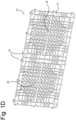
- Figure 1D shows a bottom view of the panel 10.
- Panel 10 includes connection level 12 with receiving cavities 14, protrusions 16 and side connection elements 18.
- Connection level 12 extends around outer perimeter of panel 10 and through a center 20 of the long sides of panel 10.
- Each short side of panel 10 includes three side connection elements 18, and each long side includes six side connection elements 18, though different embodiments could have different numbers of side connection elements 18.
- Panel 10 also includes box bases 22, which are elevated with respect to connection level 12 and are located on both sides of center 20 of connection level 12.
- Box base 22 can further include side walls 24, which in the embodiment shown extend in a curved manner around the corners of the box bases 22, leaving box base 22 in a rounded cross or + shape.
- the corners 26 located outside walls 24 can be elevated with respect to connection level 12, but not as high as box base 22.
- Panel 10 can be formed of a plastic material, or another material which has sufficient strength and durability.
- panel 10 could be formed as one integral piece through injection moulding or another suitable production method, or could be formed in a number of pieces and joined together.
- connection level 12 H CL could be 15 mm; height of corners He could be 30 mm; height of box base H BB could be 50 mm; and height of side walls 24 H SW could be 65 mm.
- panel 10 includes openings from a top to bottom of panel 10 throughout the central box bases 22 and areas inside of the connection level 12.
- Outer perimeter and center 20 of connection level 12 include few to no openings with the exception of cavities 14 for receiving connecting elements (feet 54) of a box 30, and could either be through holes or blind holes.
- the openings through panel 10 allow liquid to travel through the panel, and could have a different configuration in other embodiments.
- the surface of box base 22 can include a different configuration, for example, smaller spaced openings in that area as shown in Figs. 1A-1D . This can be useful to ensure any devices travelling on that surface do not become stuck or fall through openings.
- Figure 2A shows a perspective view of two boxes 30 connected to a panel 10
- Figure 2B shows a view of Fig. 2A with parts of boxes 30 removed for viewing purposes
- Figure 2C shows a perspective bottom view of a box 30.
- the long sides of panel 10 are twice as long as the short sides allowing for two boxes 30 to be connected, though other embodiments could have a different configuration.
- Each box 30 includes upper frame 32, lower frame 34 and pillars 36, which form first side 40, second side 42, first end 44, second end 46.
- First side 40 connects to first end 44 and second end 46 at hinges 50 on each of upper frame 32 and lower frame 34.
- Second side 42 also connects to each of first end 44 and second end 46 at hinges 50 on upper frame 32 and lower frame 34.
- Pillars 36 extend between upper frame 32 and lower frame 34 on each of first and second sides 40, 42 and first and second ends 44, 46. Pillars 36 are shown as three oval shaped columns 37a, 37b, 37c connected to each other, though could have a different configuration, for example a different shape (e.g., cylindrical, prism) and/or number of columns. The connections are typically a planar extension between the columns, which help to increase the strength and prevent buckling.
- Upper frame 32 on its upper surface, includes a cavity 52 aligned with the top of each column 37a, 37b, 37c.
- a foot 54 extends from the lower surface of lower frame 34 aligned with the bottom of each column 37a, 37b, 37c.
- Each foot 54 is configured to fit into a cavity 52 of a box 30 or cavity 14 of panel 10 such that boxes 30 can stack on top of one another with feet 54 of the upper box fitting into cavities 52 of the lower box, or that feet 54 secure to cavities 14 in connection level 12 of panel 10.
- Feet 54 and/or cavities 52/14 can include locking features such that the feet 54 require a large amount of force to be removed from cavities, or even that feet 54 cannot be pulled out of the cavities 52/14 once inserted.
- Such a locking mechanism could be related to the sizing and/or include other features such as a flange, ridge, shoulder, projection(s), etc.
- Hinges 50 connecting sides 40, 42 and ends 44, 46 are rotatable hinges to rotate the box from a flat or collapsed configuration to a use state (use state is shown in FIGS. 2A-2C ). This is shown and described in more detail in NL application number 2029173, titled Foldable Rainwater box, which was filed 10 September 2021 , which is hereby incorporated by reference.
- box 30 connects to connection level 12, with feet 54 connecting to cavities 14 on panel 10.
- Protrusions 16 can extend into the underside of lower frame 34, thereby providing stronger engagement between panel 10 and box 30.
- Box 30 surrounds elevated box base 22, and upper surface of lower frame 34 of box 30 aligns with the upper surface of box base 22 to form a continuous surface.
- Side walls 24 curve around from an inner side of a pillar 36 on one side/end of a box 30 to an inner side of a pillar 36 on an adjacent side/end of the box 30.
- pathways are formed through boxes 30 on the surfaces of box base 22 and lower frame 34. These pathways can be used for cleaning and inspection, allowing cleaning and/or inspection devices to easily travel from one box to another on box bases 22, not having to move over frames, lips, etc. as the upper surface of lower frame 34 and upper surface of box base 22 align to form the pathway.
- the pathways are typically planar, though can include small variations in height in some embodiments.
- Forming panel 10 to connect to two or more boxes 30 provides more strength and stability to the overall structure.
- the single panel engaging two or more boxes 30 ensures that there is very little lateral shifting or movement, thereby forming an overall more stable structure. Additionally, panels 10 could be shifted so that they do not fully align throughout a base or top of a structure, further adding stability.
- panel 10 could be formed larger to accommodate more than two boxes, for example, four boxes 30.
- Other embodiments could form a panel which was square, and the size of one box.
- FIG. 3A shows a view of two panels 10 being connected together side by side through connection elements 18.
- each connection element 18 is identical and includes a protruding part 70 and a receiving part 72 which are complementary shaped such that a protruding part 70 fits into a receiving part 72 and vice versa.
- the connection elements 18 are arranged such that panels can be connected together in an aligned manner such as shown in Fig. 3A or in a shifted manner such as shown in Fig. 3B .
- the shifted manner can help to add stability to the structure in different directions.
- the panels 10 in Fig. 3A are aligned and connected together on their long sides to secure together in the same plane through six connection elements 18.
- the panels 10 are connected together, by aligning the connection elements 18 of one panel with the connection elements 18 of the other panel 10 and moving in a direction perpendicular to the plane of the panel 10, causing the connection elements 18 of one panel to slide into the connection elements 18 of the other panel 10.
- connection elements 18 are secured together such that the protruding portion 70 of one connection element 18 is slid into the receiving portion 72 of the other element and vice versa. This secures the panels 10 together in the same plane such that connecting levels 12 align in the same plane and box bases 22 align in the same plane.
- connection elements 18 By using identical connection elements 18 with complementary paired receiving portions 72 and protruding portions 70, the panels 10 can be easily secured together, freely mounting any connection element 18 to any other connection element. This allows for easy connection, making time-consuming aligning and orienting superfluous, for example, to mate a male element with a female element. Additionally, this allows for connecting a plurality of panels 10 to form complex and/or lengthy drainage structures more easily and quickly. By making time-consuming positioning and orientation superfluous due to the identical connection elements 18 which can secure to any other connection element, the panels 10 can be easily and simply secured together.
- panels 10 have been shown and described as base panels, they could also form top panels for an array of boxes 80 such as that shown in Fig. 4 .
- Panels 10 could form a base and/or top of such a structure, with the elevated (box base) portions and connecting cavities and protrusions ensuring that boxes 30 and panels 10 stay securely engaged whether the panel 10 is on top of or beneath the box.
- box bases 22 form an inspection and/or cleaning pathway throughout the structure no matter how large.
- panels could even be used at intermediate levels, for example, every two or three stacks of boxes, and could provide a stabilizing influence as well as an additional inspection path at those positions.
- panel 10 with a connection level and an elevated box base form a strong base and/or top for a rainwater box and/or modular array of rainwater boxes connected together.
- the connection level with connection members provides a stable and strong engagement of one or more boxes, and elevated box base forms pathways from one box to another allowing inspection and/or cleaning devices to easily travel through the boxes and/or array.
- Forming the panel 10 to accommodate two or more boxes can provide additional strength and stability to a rainwater storage structure and enable a more efficient assembly on-site, having to connect fewer base and/or top plates.
- Such a configuration with the side connectors 18 also allow for connecting at any orientation and even offsetting one panel to the next, providing strength and stability in more directions.
Landscapes
- Health & Medical Sciences (AREA)
- Life Sciences & Earth Sciences (AREA)
- Engineering & Computer Science (AREA)
- Hydrology & Water Resources (AREA)
- Public Health (AREA)
- Water Supply & Treatment (AREA)
- Sewage (AREA)
Applications Claiming Priority (1)
| Application Number | Priority Date | Filing Date | Title |
|---|---|---|---|
| NL2031593A NL2031593B1 (en) | 2022-04-14 | 2022-04-14 | Panels for Drainage Structures |
Publications (1)
| Publication Number | Publication Date |
|---|---|
| EP4261355A1 true EP4261355A1 (fr) | 2023-10-18 |
Family
ID=82781286
Family Applications (1)
| Application Number | Title | Priority Date | Filing Date |
|---|---|---|---|
| EP23167806.1A Pending EP4261355A1 (fr) | 2022-04-14 | 2023-04-13 | Panneaux pour structures de drainage |
Country Status (2)
| Country | Link |
|---|---|
| EP (1) | EP4261355A1 (fr) |
| NL (1) | NL2031593B1 (fr) |
Citations (5)
| Publication number | Priority date | Publication date | Assignee | Title |
|---|---|---|---|---|
| JP2004019122A (ja) * | 2002-06-12 | 2004-01-22 | Sekisui Chem Co Ltd | 雨水等を貯留及び/又は浸透する施設及びこの施設に使用する充填部材 |
| US20080166182A1 (en) * | 2005-02-04 | 2008-07-10 | Paddy Smith | Subsurface Stormwater System |
| EP2909385A1 (fr) * | 2012-09-03 | 2015-08-26 | Polypipe Limited | Structure de drainage souterraine et son unité de base |
| US20170292260A1 (en) * | 2014-09-19 | 2017-10-12 | Wavin B.V. | A plastic infiltration unit, a system comprising a plurality of plastic infiltration units, a method of manufacturing an injection molded plastic pillar for an infiltration unit, a plastic base plate for use with a plastic infiltration unit, and a plastic infiltration system for deployment underground comprising a plastic infiltration unit |
| NL2029173B1 (en) | 2021-09-10 | 2023-03-21 | Pipelife Nederland Bv | Foldable rainwater box |
-
2022
- 2022-04-14 NL NL2031593A patent/NL2031593B1/en active
-
2023
- 2023-04-13 EP EP23167806.1A patent/EP4261355A1/fr active Pending
Patent Citations (5)
| Publication number | Priority date | Publication date | Assignee | Title |
|---|---|---|---|---|
| JP2004019122A (ja) * | 2002-06-12 | 2004-01-22 | Sekisui Chem Co Ltd | 雨水等を貯留及び/又は浸透する施設及びこの施設に使用する充填部材 |
| US20080166182A1 (en) * | 2005-02-04 | 2008-07-10 | Paddy Smith | Subsurface Stormwater System |
| EP2909385A1 (fr) * | 2012-09-03 | 2015-08-26 | Polypipe Limited | Structure de drainage souterraine et son unité de base |
| US20170292260A1 (en) * | 2014-09-19 | 2017-10-12 | Wavin B.V. | A plastic infiltration unit, a system comprising a plurality of plastic infiltration units, a method of manufacturing an injection molded plastic pillar for an infiltration unit, a plastic base plate for use with a plastic infiltration unit, and a plastic infiltration system for deployment underground comprising a plastic infiltration unit |
| NL2029173B1 (en) | 2021-09-10 | 2023-03-21 | Pipelife Nederland Bv | Foldable rainwater box |
Also Published As
| Publication number | Publication date |
|---|---|
| NL2031593B1 (en) | 2023-11-06 |
Similar Documents
| Publication | Publication Date | Title |
|---|---|---|
| DK2807312T3 (en) | COLLECTION OF TWO DRAIN BODIES | |
| AU2010305511B2 (en) | Drainage body | |
| US7677835B2 (en) | Drainage cell modular raintank and water storage system | |
| KR101121820B1 (ko) | 골격 블록, 골격 블록 조립 구조, 골격 블록의 내크리프성 향상 방법 및 골격 블록 조립 구조의 내전단하중 또는 경사방향하중의 향상 방법 | |
| EP3194674B1 (fr) | Unité d'infiltration en plastique, système comprenant une pluralité d'unités d'infiltration en plastique | |
| US20230212848A1 (en) | Stormwater Box With Trusses | |
| US12540466B2 (en) | Stormwater box with pyramidal polyhedron bracing | |
| CN104220679B (zh) | 用于雨水贮存层叠结构体的结构部件 | |
| NL2024967B1 (en) | Anchoring device for anchoring a floating solar panel assembly and solar panel assembly | |
| KR20140135238A (ko) | 빗물 저류 적층 구조체에 사용하는 구조 부재 | |
| EP4261355A1 (fr) | Panneaux pour structures de drainage | |
| US20020124332A1 (en) | Knockdown ramp construction | |
| EP3472397B1 (fr) | Panneaux de verrouillage destinés à des structures de drainage | |
| EP4261356A1 (fr) | Boîte à eau de pluie avec connecteurs latéraux | |
| EP4148194A1 (fr) | Boîte à eau de pluie pliable | |
| EP3039197B1 (fr) | Drainage | |
| US20250179787A1 (en) | Stormwater system having multiple plates and one-piece columns | |
| TW202603259A (zh) | 免拆模快速組裝筏基結構 | |
| KR200391039Y1 (ko) | 조립식 옹벽의 구조 | |
| AU2021215130A1 (en) | A foundation device | |
| WO2022087649A1 (fr) | Dispositif de fondation | |
| HK40037324A (en) | Rainwater storage and infiltration facility | |
| CN111663633A (zh) | 雨水蓄存及入渗设施 | |
| HK1241950A1 (en) | Flooring module |
Legal Events
| Date | Code | Title | Description |
|---|---|---|---|
| PUAI | Public reference made under article 153(3) epc to a published international application that has entered the european phase |
Free format text: ORIGINAL CODE: 0009012 |
|
| STAA | Information on the status of an ep patent application or granted ep patent |
Free format text: STATUS: THE APPLICATION HAS BEEN PUBLISHED |
|
| AK | Designated contracting states |
Kind code of ref document: A1 Designated state(s): AL AT BE BG CH CY CZ DE DK EE ES FI FR GB GR HR HU IE IS IT LI LT LU LV MC ME MK MT NL NO PL PT RO RS SE SI SK SM TR |
|
| STAA | Information on the status of an ep patent application or granted ep patent |
Free format text: STATUS: REQUEST FOR EXAMINATION WAS MADE |
|
| 17P | Request for examination filed |
Effective date: 20240416 |
|
| RBV | Designated contracting states (corrected) |
Designated state(s): AL AT BE BG CH CY CZ DE DK EE ES FI FR GB GR HR HU IE IS IT LI LT LU LV MC ME MK MT NL NO PL PT RO RS SE SI SK SM TR |