EP4261436B1 - Spanneinrichtung - Google Patents
Spanneinrichtung Download PDFInfo
- Publication number
- EP4261436B1 EP4261436B1 EP23160948.8A EP23160948A EP4261436B1 EP 4261436 B1 EP4261436 B1 EP 4261436B1 EP 23160948 A EP23160948 A EP 23160948A EP 4261436 B1 EP4261436 B1 EP 4261436B1
- Authority
- EP
- European Patent Office
- Prior art keywords
- positioning element
- belt
- tensioning
- eccentric
- eccentric unit
- Prior art date
- Legal status (The legal status is an assumption and is not a legal conclusion. Google has not performed a legal analysis and makes no representation as to the accuracy of the status listed.)
- Active
Links
Images


Classifications
-
- F—MECHANICAL ENGINEERING; LIGHTING; HEATING; WEAPONS; BLASTING
- F16—ENGINEERING ELEMENTS AND UNITS; GENERAL MEASURES FOR PRODUCING AND MAINTAINING EFFECTIVE FUNCTIONING OF MACHINES OR INSTALLATIONS; THERMAL INSULATION IN GENERAL
- F16H—GEARING
- F16H7/00—Gearings for conveying rotary motion by endless flexible members
- F16H7/08—Means for varying tension of belts, ropes or chains
- F16H7/10—Means for varying tension of belts, ropes or chains by adjusting the axis of a pulley
- F16H7/12—Means for varying tension of belts, ropes or chains by adjusting the axis of a pulley of an idle pulley
- F16H7/1254—Means for varying tension of belts, ropes or chains by adjusting the axis of a pulley of an idle pulley without vibration damping means
- F16H7/1281—Means for varying tension of belts, ropes or chains by adjusting the axis of a pulley of an idle pulley without vibration damping means where the axis of the pulley moves along a substantially circular path
-
- F—MECHANICAL ENGINEERING; LIGHTING; HEATING; WEAPONS; BLASTING
- F16—ENGINEERING ELEMENTS AND UNITS; GENERAL MEASURES FOR PRODUCING AND MAINTAINING EFFECTIVE FUNCTIONING OF MACHINES OR INSTALLATIONS; THERMAL INSULATION IN GENERAL
- F16H—GEARING
- F16H7/00—Gearings for conveying rotary motion by endless flexible members
- F16H7/18—Means for guiding or supporting belts, ropes, or chains
- F16H7/20—Mountings for rollers or pulleys
-
- F—MECHANICAL ENGINEERING; LIGHTING; HEATING; WEAPONS; BLASTING
- F16—ENGINEERING ELEMENTS AND UNITS; GENERAL MEASURES FOR PRODUCING AND MAINTAINING EFFECTIVE FUNCTIONING OF MACHINES OR INSTALLATIONS; THERMAL INSULATION IN GENERAL
- F16H—GEARING
- F16H7/00—Gearings for conveying rotary motion by endless flexible members
- F16H7/08—Means for varying tension of belts, ropes or chains
- F16H2007/0802—Actuators for final output members
- F16H2007/081—Torsion springs
-
- F—MECHANICAL ENGINEERING; LIGHTING; HEATING; WEAPONS; BLASTING
- F16—ENGINEERING ELEMENTS AND UNITS; GENERAL MEASURES FOR PRODUCING AND MAINTAINING EFFECTIVE FUNCTIONING OF MACHINES OR INSTALLATIONS; THERMAL INSULATION IN GENERAL
- F16H—GEARING
- F16H7/00—Gearings for conveying rotary motion by endless flexible members
- F16H7/08—Means for varying tension of belts, ropes or chains
- F16H2007/0842—Mounting or support of tensioner
Definitions
- the invention relates to a tensioning device according to the preamble of claim 1.
- the invention also relates to a belt drive according to claim 6, a drive according to claim 8 and a vehicle according to claim 9.
- Tensioning devices are well known to the person skilled in the art. Tensioning devices can be used, for example, in belt drives to provide sufficient pre-tensioning force in a belt for reliable power transmission. A tensioning device of this type is known from DE112005002788T known.
- Belt drives are pre-tensioned with a predetermined force.
- the pre-tension force In the static state, i.e. when the belt drive is at a standstill, the pre-tension force is distributed evenly across the individual belt strands.
- the dynamic state i.e. when the belt drive is moving, the power is transmitted via a so-called load strand.
- the force in the load strand increases with the torque introduced into the belt.
- the force in the slack strand decreases by the same amount and thus the pre-tension in the slack strand also decreases.
- a belt drive can transmit so much power until the pre-tension force in the slack strand drops to a value of zero. Too little pre-tension in the slack strand can lead to the belt having increased slip or, in the case of a toothed belt, to a tendency for the teeth to jump.
- the pre-tensioning force can be applied by a tensioning device that can be arranged in the slack side of the belt. This can ensure that power transmission is as slip-free as possible in the case of force-locking belt drives, e.g. V-belts or V-ribbed belts. Toothed belt drives can effectively prevent disadvantageous tooth jumps.
- spring-loaded tensioning pulleys or eccentric tensioning pulleys can be used to tension belts.
- Eccentric tensioning pulleys are usually used to apply a fixed belt pre-tension once.
- the desired pre-tension value can be set once when installing the belt by pivoting the eccentric tensioning pulley into the slack side of the belt, thereby tensioning the slack side.
- the eccentric tensioning pulley can be fixed in position with at least one screw.
- the DE 196 34 344 A1 relates to such a tensioning device for traction devices.
- the tensioning roller is mounted on a shield plate, whereby the shield plate is pivotally connected to a machine part.
- the tensioning roller can be moved relative to the shield plate in a first slot and can be fixed with a screw.
- the shield plate can be pivoted into the belt drive with the pre-positioned tensioning roller to further apply a pre-tensioning force, whereby the pivoting path is limited by a second slot.
- the position of the tensioning device can be fixed with another screw in the second slot.
- the disadvantage is that the screw connections can become loose over a longer period of time due to settling effects, which can gradually push the eccentric tensioning roller out of the belt drive.
- the pre-tension which is already decreasing over time due to settling phenomena in the belt, can thus be further increased, which can ultimately lead to complete system failure.
- the positive locking can prevent the eccentric from turning even if the screw connection for locking the eccentric roller is loosened.
- the disadvantage is that the individual locking positions are predefined, which is why the eccentric tension roller can only be fixed in discrete locking positions. Particularly with belts with a high modulus of elasticity, i.e. high rigidity, these locking positions have the disadvantage that a precise adjustment of the pre-tension is not possible.
- the invention is based on the object of providing a tensioning device with which the risk of a loss of pre-tension in the belt as a result of a changing position of the tensioning device due to a loosening screw connection can be reduced or completely avoided.
- a precise adjustment of the pre-tensioning force and/or a continuous adjustment of the position of the tensioning device should be made possible.
- Claim 6 relates to a belt drive with a tensioning device according to the invention.
- Claim 8 relates to a drive with a belt drive according to the invention.
- Claim 9 relates to a vehicle with a drive according to the invention.
- the present application relates to a tensioning device, preferably for tensioning a belt, with a fixedly arranged first positioning element made of a first material and with at least one eccentric unit, wherein the eccentric unit has a second positioning element made of a second material, wherein the second positioning element is pivotally mounted about a pivot point, wherein the first positioning element and the second positioning element are designed to positively hold the eccentric unit on the first positioning element.
- the clamping device is characterized by a deformable clamping element arranged between the first positioning element and the second positioning element, wherein the clamping element has a third material with a lower hardness than the first material and the second material.
- the eccentric unit is fixedly connected to the second positioning element.
- the eccentric unit can be designed as an eccentric roller for a belt drive.
- the second positioning element and thus the eccentric unit can be pivoted out of the belt in a first position.
- the eccentric unit can be pivoted about the pivot point into the belt, preferably into the slack side of the belt, into a second position.
- the pivot point is arranged centrally in the second positioning element, with the second positioning element being arranged eccentrically on the eccentric unit. The pivot point is thus arranged eccentrically on the eccentric unit, which is why the eccentric unit can be pivoted eccentrically about the pivot point.
- the path by which the eccentric unit is pivoted into the belt can thus be adjusted depending on the angle by which the eccentric unit is pivoted about the pivot point.
- the pre-tensioning force of the belt can be continuously adjusted.
- the eccentric unit with the second positioning element can be rotated relative to the first positioning element, which is fixed, for example on a frame of a machine.
- the eccentric unit can be locked to the first positioning element via the second positioning element and the deformable clamping element.
- the set pre-tension in the belt can be maintained by locking the second positioning element of the eccentric unit in the desired position in a rotationally fixed manner with the first positioning element.
- the first positioning element, the clamping element and the second positioning element can each have a bore, whereby the center of the bore can correspond to the pivot point.
- the bores arranged in the first positioning element, in the clamping element and in the second positioning element can be aligned with one another in a line that can correspond to the pivot point.
- a thread can be formed in the bore of the first positioning element.
- a screw can be passed through the bore of the first positioning element, the clamping element and the second positioning element. The screw can thus penetrate the first positioning element, the clamping element and the second positioning element.
- the deformable clamping element in the form of a disk is arranged between the first positioning element and the second positioning element.
- the first positioning element has a first material
- the second positioning element has a second material.
- the first material can preferably be identical to the second material.
- the first material and the second material are particularly preferably a steel material.
- the deformable clamping element is made of a third material that has a lower hardness than the material of the first positioning element and the material of the second positioning element.
- the clamping element can be made of aluminum.
- the screw can be screwed into the thread of the first positioning element so far that the first positioning element and the second positioning element can be tightened against the clamping element.
- the positioning element can form as a negative into the clamping element with the third material of lower hardness.
- the eccentric unit can be locked in a form-fitting manner with the clamping element via the second positioning element and in a form-fitting manner with the first positioning element via the clamping element, which makes it particularly advantageous to prevent the eccentric unit from twisting when the screw is loosened. If, for example, the belt is changed, only the clamping element needs to be replaced in order to subsequently adjust the position or the angle of twist of the eccentric unit or the belt pre-tension.
- the locking position of the eccentric unit is not already determined from the outset by predefined teeth in the clamping element, but that the locking position of the eccentric unit can only be achieved by molding the, for example, tooth-shaped profile of the first positioning element and the, for example, tooth-shaped profile of the second positioning element into the clamping element after the precise and stepless adjustment of the position or the angle of rotation of the eccentric unit and, consequently, after the stepless adjustment of the pre-tension of the belt.
- the eccentric unit can be adjusted steplessly by the tensioning device according to the invention and positively locked in the optimal position.
- an eccentric tension roller axis is fixedly connected to the second positioning element and has at least one tension roller that is rotatably mounted about the tension roller axis.
- the eccentric unit has a body that is fixedly connected to the second positioning element, the body forming the tension roller axis.
- At least one tension roller is rotatably mounted on the tension roller axis, preferably by at least one ball bearing.
- several tension rollers can be arranged and mounted in parallel on the tension roller axis.
- the belt can roll on the tension roller with little friction.
- the eccentric unit designed in this way can also be called an eccentric tension roller. In this way, the properties and advantages mentioned above can be transferred to the eccentric tension pulley.
- the first material and the second material are identical.
- the first positioning element and the second positioning element are made of the same material.
- the tooth-shaped profiles of the first positioning element and the second positioning element can thus be formed symmetrically into the clamping element and, through positive locking, provide the same securing force against twisting of the eccentric unit in the locked state.
- the first positioning element and the second positioning element have a corresponding profile, wherein according to a further aspect of the present invention the profile is designed as a toothing.
- the profile is designed as a toothing, a high surface pressure in the area of the tooth tips and the clamping element can bring about a positive connection between the first positioning element, the clamping element and the second positioning element even with low clamping forces.
- the profiling of the first positioning element and the profiling of the second positioning element can be molded into the deformable clamping element as a negative.
- a positive connection between the first positioning element, the clamping element and the second positioning element can be continuously adjusted.
- the locking position of the eccentric unit can be achieved by molding the tooth-shaped profiling of the first positioning element and the tooth-shaped profiling of the second positioning element into the clamping element only after the precise and continuous adjustment of the position or the angle of rotation of the eccentric unit and, consequently, after the continuous adjustment of the pre-tension of the belt.
- the first positioning element and the second positioning element are designed to be pressed axially against the clamping element, preferably via a screw connection.
- a screw connection offers the particular advantage that the force with which the first positioning element and the second positioning element are pressed against the clamping element can be adjusted by the tightening torque of the screw.
- a screw connection also offers the further advantage that the connection can be released without causing any damage and can enable the clamping device to be dismantled.
- the invention also relates to a belt drive with a tensioning device according to the invention.
- the properties and advantages of the tensioning device according to the invention described above can thus be transferred to any belt drive.
- Belt drives are used, for example, for power transmission between at least two shafts in different machines, systems or vehicles.
- the belt drive according to the invention can include both belts for positive power transmission, such as toothed belts, and belts for frictional power transmission, such as flat belts, V-belts or V-ribbed belts.
- the tensioning device is designed to tension a slack side of the belt, wherein the tension roller can be rolled on the slack side of the belt.
- the arrangement of the tensioning device in the slack side of the belt is particularly advantageous, since the slack side loses pre-tensioning force as the power transmission increases and must be tensioned accordingly.
- the arrangement of the tensioning device according to the invention in each belt side can be advantageous.
- the invention further relates to a drive with a belt drive according to the invention.
- the properties and advantages mentioned above can thus be transferred to any drives with a belt drive.
- the invention also relates to a vehicle with at least one drive according to the invention.
- Vehicles can be understood to mean all types of land, water or air vehicles.
- this can be advantageously increased by the tensioning device according to the invention.
- the description of the above figures is made in Cartesian coordinates with a longitudinal direction X, a transverse direction Y perpendicular to the longitudinal direction X and a vertical direction Z perpendicular to both the longitudinal direction X and the transverse direction Y.
- the longitudinal direction X can also be referred to as depth X
- the transverse direction Y as width Y
- the vertical direction Z as height Z.
- the longitudinal direction X and the transverse direction Y together form the horizontal, X, Y, which can also be referred to as the horizontal plane X, Y.
- the longitudinal direction X, the transverse direction Y and the vertical direction Z can collectively referred to as spatial directions X, Y, Z or as Cartesian spatial directions X, Y, Z.
- FIG 1 shows the schematic representation of an eccentric unit 5 of a tensioning device 1 in a frontal view.
- the eccentric unit 5 has a second positioning element 6, wherein the second positioning element 6 is pivotally mounted about a pivot point 4.
- the eccentric unit 5 also has an eccentric tension roller axis 3, which is fixedly connected to the second positioning element 6.
- a tension roller 2 is rotatably mounted on the tension roller axis 3.
- the entire eccentric unit 5 can pivot about the eccentric pivot point 4.
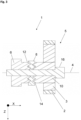
- FIG. 2 shows a sectional view of the clamping device 1 according to the invention in a side view in a first position in an unlocked state.
- the clamping device 1 comprises a first positioning element 6, a deformable clamping element 8 and the eccentric unit 5.
- the first positioning element 6 has a tooth-shaped profile 12.
- the second positioning element 10 has a further tooth-shaped profile 14, which is designed to correspond to the tooth-shaped profile 12 of the first positioning element 6.
- the first positioning element 6 is part of a machine frame or is connected to a machine frame (not shown).
- the deformable clamping element 8 in the form of a disk is arranged between the first positioning element 6 and the second positioning element 10.
- the deformable clamping element 8 is made of a material that has a lower hardness than the material of the first positioning element 6 and the material of the second positioning element 10. In this embodiment, the deformable clamping element 8 is made of aluminum.
- the first positioning element 6 and the second positioning element 10 are made of a steel material.
- the first positioning element 6, the deformable clamping element 8 and the second positioning element 10 each have a bore (not designated), whereby the center of the hole corresponds to the eccentric pivot point 4.
- the holes arranged in the first positioning element 6, in the deformable clamping element 8 and in the second positioning element 10 are aligned with one another along the longitudinal direction X in a line that corresponds to the pivot point 4.
- a thread (not shown in detail) is formed in the hole of the first positioning element 6.
- a screw 16 is passed through the hole. The screw 16 passes through the first positioning element 6, the deformable clamping element 8 and the second positioning element 10.
- the screw 16 is only screwed into the thread of the first positioning element 6 to such an extent that the tooth-shaped profile 12 of the first positioning element 6 and the tooth-shaped profile 14 of the second positioning element 10 rest on the surface of the deformable clamping element 8 with little force or without force.
- the eccentric unit 5 can be pivoted eccentrically and continuously about the pivot point 4.
- the teeth of the profile 12 of the first positioning element 6 slide on the surface of the clamping element 8 when the eccentric unit 5 rotates about the pivot point 4.
- Fig. 3 shows the sectional view of the clamping device 1 according to the invention in a side view in a second position in a locked state.
- the eccentric unit 5 is shown rotated about the pivot point 4.
- a belt strand (not shown in detail) running over the tension roller 2 would be tensioned in this way.
- the screw 16 is screwed into the thread of the first positioning element 6 so far that the first positioning element 6 and the second positioning element 10 are tightened in the longitudinal direction X against the deformable clamping element 8.
- the tooth-shaped profile 12 of the first positioning element 6 and the tooth-shaped profile 14 of the second positioning element 10 are formed as a negative in the clamping element 8.
- the eccentric unit 5 is positively locked to the clamping element 8 via the second positioning element 10 and to the first positioning element 6 via the clamping element 8, which prevents the eccentric unit 5 from twisting when the screw 16 is loosened.
- a continuous positioning in the circumferential direction of the pivot point 4 can take place, which would not be possible without the use of the clamping element 8.
Landscapes
- Engineering & Computer Science (AREA)
- General Engineering & Computer Science (AREA)
- Mechanical Engineering (AREA)
- Devices For Conveying Motion By Means Of Endless Flexible Members (AREA)
Description
- Die Erfindung betrifft eine Spanneinrichtung gemäß dem Oberbegriff des Anspruchs 1. Die Erfindung betrifft außerdem einen Riementrieb gemäß Anspruch 6, einen Antrieb gemäß Anspruch 8 und ein Fahrzeug gemäß Anspruch 9.
- Spanneinrichtungen sind dem Fachmann aus dem Stand der Technik hinreichend bekannt. Spanneinrichtungen können zum Beispiel in Riementrieben eingesetzt werden, um eine ausreichende Vorspannkraft in einem Riemen für eine zuverlässige Leistungsübertragung zur Verfügung zu stellen. Eine gattungsgemäße Spanneinrichtung ist aus der
DE112005002788T bekannt. - Riementriebe sind mit einer vorbestimmten Kraft vorgespannt. Die Vorspannkraft verteilt sich im statischen Zustand, d.h. bei Stillstand des Riementriebs, gleichmäßig auf die einzelnen Riementrume. Im dynamischen Zustand, d.h. bei einem sich bewegenden Riementrieb, erfolgt die Leistungsübertragung über ein so genanntes Lasttrum. Die Kraft im Lasttrum steigt mit dem in den Riemen eingeleiteten Drehmoment an. Betragsmäßig sinkt die Kraft im Leertrum in gleichem Maße und somit verringert sich auch die Vorspannung im Leertrum. Mit anderen Worten gesagt kann mit einem Riementrieb im Idealzustand so viel Leistung übertragen werden, bis die Vorspannkraft im Leertrum auf einen Wert von Null sinkt. Eine zu geringe Vorspannkraft im Leertrum kann nämlich dazu führen, dass der Riemen einen erhöhten Schlupf aufweist oder im Falle eines Zahnriemens zu einem Überspringen der Zähne neigt.
- Das Aufbringen der Vorspannkraft kann durch eine Spanneinrichtung erfolgen, die im Leertrum des Riemens angeordnet sein kann. Damit kann im Falle von kraftschlüssigen Riementrieben, z. B. bei Keilriemen oder Keilrippenriemen, eine möglichst schlupfarme Leistungsübertragung sichergestellt werden. Bei Zahnriementrieben kann ein nachteiliger Zahnsprung wirksam unterbunden werden.
- So können zum Spannen von Riemen zum Beispiel federgespannte Spannrollen oder Exzenterspannrollen verwendet werden. Exzenterspannrollen werden üblicher Weise für das einmalige Aufbringen einer festen Riemenvorspannung verwendet. Im Gegensatz zu einer federgespannten automatischen Spannrolle kann der gewünschte Vorspannungswert bei der Riemenmontage einmalig eingestellt werden, indem die Exzenterspannrolle in das Leertrum des Riemens geschwenkt wird und das Leertrum somit spannt. Die Exzenterspannrolle kann mit wenigstens einer Schraube in ihrer Position fixiert werden.
- Die
DE 196 34 344 A1 betrifft eine solche Spanneinrichtung für Zugmittel. Die Spannrolle ist in diesem Beispiel an einer Schildplatte montiert, wobei die Schildplatte schwenkbar an ein Maschinenteil angebunden ist. Zur Einstellung der Vorspannkraft des Riemens ist die Spannrolle in einem ersten Langloch relativ zur Schildplatte verschiebbar und durch eine Schraube festsetzbar. Die Schildplatte kann mit der vorpositionierten Spannrolle zur weiteren Aufbringung einer Vorspannkraft in den Riementrieb geschwenkt werden, wobei der Schwenkweg über ein zweites Langloch begrenzt ist. Die Position der Spanneinrichtung kann über eine weitere Schraube in dem zweiten Langloch festgesetzt werden. - Nachteiliger Weise können sich die Schraubverbindungen durch Setzeffekte über einen längeren Zeitraum lockern, wodurch die Exzenterspannrolle sukzessive aus dem Riementrieb gedrückt werden kann. Die durch Setzungserscheinungen im Riemen über die Laufzeit ohnehin schon abfallende Vorspannung kann so zusätzlich verstärkt werden, was schlussendlich zu einem vollständigen Systemversagen führen kann.
- Um dies zu verhindern, ist zum Beispiel eine zusätzliche formschlüssige Arretierung der Exzenterrolle bekannt. Durch den Formschluss kann auch bei Lockerung der Schraubverbindung zur Arretierung der Exzenterrolle ein Verdrehen des Exzenters verhindert werden.
- Nachteiliger Weise sind die einzelnen Arretierungspositionen vordefiniert, weshalb die Fixierung der Exzenterspannrolle nur in diskreten Rastpositionen möglich ist. Insbesondere bei Riemen mit einem hohen Elastizitätsmodul, d. h. einer hohen Steifigkeit, haben diese Rastpositionen den Nachteil, dass eine präzise Einstellung der Vorspannung nicht möglich ist.
- Der Erfindung liegt die Aufgabe zugrunde, eine Spanneinrichtung bereitzustellen, mit der das Risiko eines Vorspannungsverlustes im Riemen in Folge einer sich verändernden Position der Spanneinrichtung durch eine sich lösende Schraubverbindung verringert bzw. vollständig vermieden werden kann. Zusätzlich oder alternativ soll eine präzise Einstellung der Vorspannkraft und bzw. oder eine stufenlose Verstellung der Position der Spanneinrichtung ermöglicht werden.
- Die Lösung dieser Aufgabe ergibt sich durch eine Spanneinrichtung mit den Merkmalen des unabhängigen Anspruchs 1.
- Anspruch 6 betrifft einen Riementrieb mit einer erfindungsgemäßen Spanneinrichtung.
- Anspruch 8 betrifft einen Antrieb mit einem erfindungsgemäßen Riementrieb.
- Anspruch 9 betrifft ein Fahrzeug mit einem erfindungsgemäßen Antrieb.
- Weitere vorteilhafte Ausbildungen sind in den abhängigen Ansprüchen offenbart.
- Die vorliegende Anmeldung betrifft eine Spanneinrichtung, vorzugsweise zum Spannen eines Riemens, mit einem feststehend angeordneten ersten Positionierelement aus einem ersten Material und mit wenigstens einer Exzentereinheit, wobei die Exzentereinheit ein zweites Positionierelement aus einem zweiten Material aufweist, wobei das zweite Positionierelement um einen Drehpunkt schwenkbar gelagert ist, wobei das erste Positionierelement und das zweite Positionierelement zum formschlüssigen Halt der Exzentereinheit am ersten Positionierelement ausgebildet sind.
- Die Spanneinrichtung ist gekennzeichnet durch ein zwischen dem ersten Positionierelement und dem zweiten Positionierelement angeordnetes verformbares Klemmelement, wobei das Klemmelement ein drittes Material mit einer geringeren Härte als das erste Material und das zweite Material aufweist.
- Mit anderen Worten gesagt ist die Exzentereinheit feststehend mit dem zweiten Positionierelement verbunden. Die Exzentereinheit kann als eine Exzenterrolle für einen Riementrieb ausgebildet sein. Für eine kraftfreie Montage des Riemens kann das zweite Positionierelement und somit die Exzentereinheit in einer ersten Position aus dem Riemen herausgeschwenkt sein. Zum Vorspannen des Riemens kann die Exzentereinheit um den Drehpunkt in den Riemen, vorzugsweise in das Leertrum des Riemens, in eine zweite Position hineingeschwenkt werden. Der Drehpunkt ist zentrisch in dem zweiten Positionierelement angeordnet, wobei das zweite Positionierelement exzentrisch an der Exzentereinheit angeordnet ist. Somit ist der Drehpunkt exzentrisch an der Exzentereinheit angeordnet, weshalb die Exzentereinheit exzentrisch um den Drehpunkt schwenkbar ist. So kann der Weg, mit dem die Exzentereinheit in den Riemen hineingeschwenkt wird, in Abhängigkeit des Winkels, um den die Exzentereinheit um den Drehpunkt geschwenkt wird, eingestellt werden. In Abhängigkeit des Weges, mit dem die Exzentereinheit in den Riemen hineingeschwenkt wird, kann die Vorspannkraft des Riemens stufenlos eingestellt werden. Die Exzentereinheit mit dem zweiten Positionierelement kann mit anderen Worten gesagt relativ zu dem feststehend, zum Beispiel an einem Rahmen einer Maschine, angeordneten ersten Positionierelement verdreht werden.
- Die Exzentereinheit kann über das zweite Positionierelement und das verformbare Klemmelement mit dem ersten Positionierelement arretiert werden.
- Die eingestellte Vorspannung im Riemen kann aufrechterhalten werden, indem das zweite Positionierelement der Exzentereinheit verdrehfest mit dem ersten Positionierelement in der gewünschten Position arretiert wird. Hierzu kann das erste Positionierelement, das Klemmelement und das zweite Positionierelement jeweils eine Bohrung aufweisen, wobei der Mittelpunkt der Bohrung dem Drehpunkt entsprechen kann. Mit anderen Worten gesagt können die in dem ersten Positionierelement, in dem Klemmelement und in dem zweiten Positionierelement angeordneten Bohrungen in einer Linie, die dem Drehpunkt entsprechen kann, fluchtend zueinander liegen. In der Bohrung des ersten Positionierelements kann ein Gewinde ausgebildet sein. Durch die Bohrung des ersten Positionierelements, des Klemmelements und des zweiten Positionierelements kann eine Schraube hindurchgeführt sein. Die Schraube kann so das erste Positionierelement, das Klemmelement und das zweite Positionierelement durchgreifen.
- Zwischen dem ersten Positionierelement und dem zweiten Positionierelement ist das verformbare Klemmelement in Form einer Scheibe angeordnet. Das erste Positionierelement weist ein erstes Material auf, wobei das zweite Positionierelement ein zweites Material aufweist. Vorzugsweise kann das erste Material mit dem zweiten Material identisch ausgebildet sein. Besonders bevorzugt sind das erste Material und das zweite Material ein Stahlwerkstoff. Das verformbare Klemmelement ist aus einem dritten Material ausgebildet, das eine geringere Härte als das Material des ersten Positionierelements und das Material des zweiten Positionierelements aufweist. Das Klemmelement kann aus Aluminium ausgebildet sein.
- Zur Arretierung der Exzentereinheit kann die Schraube so weit in das Gewinde des ersten Positionierelements eingeschraubt werden, sodass das erste Positionierelement und das zweite Positionierelement gegen das Klemmelement angezogen werden können. Eine zum Beispiel zahnförmige Profilierung des ersten Positionierelements und eine zahnförmige Profilierung des zweiten Positionierelements können sich aufgrund des Materials größerer Härte als Negativ in das Klemmelement mit dem dritten Material geringerer Härte einformen.
- Die Exzentereinheit kann auf diese Weise über das zweite Positionierelement formschlüssig mit dem Klemmelement und über das Klemmelement formschlüssig mit dem ersten Positionierelement arretiert werden, wodurch ein Verdrehen der Exzentereinheit bei gelöster Schraube besonders vorteilhaft vermieden werden kann. Bei zum Beispiel einem Wechsel des Riemens muss für das anschließende Einstellen der Position bzw. des Verdrehwinkels der Exzentereinheit bzw. der Riemenvorspannung lediglich das Klemmelement erneuert werden.
- Es zeigt sich als besonders vorteilhaft, dass die Arretierungsposition der Exzentereinheit nicht bereits durch in dem Klemmelement vordefinierte Verzahnungen von vorn herein bestimmt ist, sondern dass die Arretierungsposition der Exzentereinheit durch das Einformen der zum Beispiel zahnförmigen Profilierung des ersten Positionierelements und der zum Beispiel zahnförmigen Profilierung des zweiten Positionierelements in das Klemmelement erst nach dem präzisen und stufenlosen Einstellen der Position bzw. des Verdrehwinkels der Exzentereinheit und daraus folgend nach der stufenlosen Einstellung der Vorspannung des Riemens erfolgen kann. Mit anderen Worten gesagt kann die Exzentereinheit durch die erfindungsgemäße Spanneinrichtung stufenlos verstellt und in der optimalen Position formschlüssig arretiert werden.
- Gemäß einem weiteren Aspekt der vorliegenden Erfindung ist eine exzentrische Spannrollenachse feststehend mit dem zweiten Positionierelement verbunden und weist wenigstens eine um die Spannrollenachse drehbar gelagerte Spannrolle auf. Mit anderen Worten gesagt weist die Exzentereinheit einen mit dem zweiten Positionierelement feststehend verbundenen Körper auf, wobei der Körper die Spannrollenachse bildet. Auf der Spannrollenachse ist wenigstens eine Spannrolle drehbar gelagert, vorzugsweise durch wenigstens ein Kugellager. Alternativ können auf mehrere Spannrollen parallel auf der Spannrollenachse angeordnet und gelagert sein. Auf der Spannrolle kann der Riemen reibungsarm abrollen. Die auf diese Weise ausgebildete Exzentereinheit kann auch Exzenterspannrolle genannt werden. So können die zuvor genannten Eigenschaften und Vorteile auf die Exzenterspannrolle übertragen werden.
- Gemäß einem weiteren Aspekt der vorliegenden Erfindung ist das erste Material und das zweite Material identisch ausgebildet. Mit anderen Worten gesagt sind das erste Positionierelement und das zweite Positionierelement aus dem gleichen Material ausgebildet. Die zahnförmigen Profilierungen des ersten Positionierelements und des zweiten Positionierelements können sich so symmetrisch in das Klemmelement einformen und durch Formschluss die jeweils gleiche Sicherungskraft gegen ein Verdrehen der Exzentereinheit im arretierten Zustand bereitstellen.
- Gemäß der vorliegenden Erfindung weisen das erste Positionierelement und das zweite Positionierelement eine korrespondierende Profilierung auf, wobei gemäß einem weiteren Aspekt der vorliegenden Erfindung die Profilierung als eine Verzahnung ausgebildet ist. Insbesondere bei Ausbildung der Profilierung als Verzahnung kann durch eine hohe Flächenpressung im Bereich der Zahnspitzen und dem Klemmelement eine formschlüssige Verbindung zwischen dem ersten Positionierelement, dem Klemmelement und dem zweiten Positionierelement schon bei geringen Klemmkräften herbeigeführt werden.
- Gemäß der vorliegenden Erfindung sind die Profilierung des ersten Positionierelements und die Profilierung des zweiten Positionierelements als Negativ in das verformbare Klemmelement einformbar. Auf besonders vorteilhafte Weise kann eine formschlüssige Verbindung zwischen dem ersten Positionierelement, dem Klemmelement und dem zweiten Positionierelement stufenlos eingestellt werden. Die Arretierungsposition der Exzentereinheit kann durch das Einformen der zahnförmigen Profilierung des ersten Positionierelements und der zahnförmigen Profilierung des zweiten Positionierelements in das Klemmelement erst nach dem präzisen und stufenlosen Einstellen der Position bzw. des Verdrehwinkels der Exzentereinheit und daraus folgend nach der stufenlosen Einstellung der Vorspannung des Riemens erfolgen.
- Gemäß einem weiteren Aspekt der vorliegenden Erfindung sind das erste Positionierelement und das zweite Positionierelement ausgebildet, axial gegen das Klemmelement gepresst zu werden, vorzugsweise über eine Schraubverbindung. Eine Schraubverbindung bietet insbesondere den Vorteil, dass die Kraft, mit welcher das erste Positionierelement und das zweite Positionierelement gegen das Klemmelement gepresst werden, durch das Anzugsmoment der Schraube einstellbar ist. Außerdem bietet eine Schraubverbindung als weiteren Vorteil, dass die Verbindung zerstörungsfrei lösbar ist und eine Demontage der Spanneinrichtung ermöglichen kann.
- Die Erfindung betrifft außerdem einen Riementrieb mit einer erfindungsgemäßen Spanneinrichtung. Die zuvor beschriebenen Eigenschaften und Vorteile der erfindungsgemäßen Spanneinrichtung lassen sich so auf beliebige Riementriebe übertragen. Riementriebe finden beispielsweise Anwendung zur Leistungsübertragung zwischen wenigstens zwei Wellen in unterschiedlichen Maschinen, Anlagen oder Fahrzeugen. Der erfindungsgemäße Riementrieb kann sowohl Riemen zur formschlüssigen Kraftübertragung wie zum Beispiel Zahnriemen als auch Riemen zur reibschlüssigen Kraftübertragung wie zum Beispiel Flachriemen, Keilriemen oder Keilrippenriemen umfassen.
- Gemäß einem weiteren Aspekt der vorliegenden Erfindung ist die Spanneinrichtung zum Spannen eines Leertrums des Riemens ausgebildet, wobei die Spannrolle auf dem Leertrum des Riemens abrollbar ist. Insbesondere ist die Anordnung der Spanneinrichtung im Leertrum des Riemens besonders vorteilhaft, da das Leertrum bei steigender Leistungsübertragung an Vorspannkraft verliert und entsprechend gespannt werden muss. Bei Riementrieben mit Richtungs- und bzw. oder Drehmomentumkehr und einem Wechsel zwischen Lasttrum und Leertrum kann die Anordnung der erfindungsgemäßen Spanneinrichtung in jedem Riementrum vorteilhaft sein.
- Die Erfindung betrifft weiterhin einen Antrieb mit einem erfindungsgemäßen Riementrieb. Die zuvor genannten Eigenschaften und Vorteile lassen sich so auf beliebige Antriebe mit einem Riementrieb übertragen.
- Die Erfindung betrifft auch ein Fahrzeug mit wenigstens einem erfindungsgemäßen Antrieb. Die zuvor genannten Eigenschaften und Vorteile lassen sich so bei Antrieben verschiedener Fahrzeuge anwenden. Unter Fahrzeugen können Land-, Wasser- oder Luftfahrzeuge aller Art verstanden werden. Insbesondere bei Fahrzeugen, bei denen die Funktionssicherheit des Antriebs einen besonders großen Stellenwert hat, kann diese durch die erfindungsgemäße Spanneinrichtung auf vorteilhafte Weise erhöht werden.
- Es wird ausdrücklich darauf hingewiesen, dass die vorstehend erläuterten Ausgestaltungen der Erfindung jeweils für sich oder in einer beliebigen technisch sinnvollen Kombination auch untereinander jeweils mit dem Gegenstand des Anspruchs 1 und bzw. oder den übrigen unabhängigen Ansprüchen kombinierbar sind.
- Verschiedene Ausführungsbeispiele und weitere Vorteile der Erfindung werden nachstehend in Zusammenhang mit den folgenden schematischen Figuren erläutert. Darin zeigt:
-
Fig. 1 eine frontale Ansicht einer erfindungsgemäßen Spanneinrichtung. -
Fig. 2 eine Schnittdarstellung der erfindungsgemäßen Spanneinrichtung in einer Seitenansicht in einer ersten Position in einem nicht arretierten Zustand. -
Fig. 3 die Schnittdarstellung der erfindungsgemäßen Spanneinrichtung in der Seitenansicht in einer zweiten Position in einem arretierten Zustand. - Die Beschreibung der o.g. Figuren erfolgt in kartesischen Koordinaten mit einer Längsrichtung X, einer zur Längsrichtung X senkrecht ausgerichteten Querrichtung Y sowie einer sowohl zur Längsrichtung X als auch zur Querrichtung Y senkrecht ausgerichteten vertikalen Richtung Z. Die Längsrichtung X kann auch als Tiefe X, die Querrichtung Y auch als Breite Y und die vertikale Richtung Z auch als Höhe Z bezeichnet werden. Die Längsrichtung X und die Querrichtung Y bilden gemeinsam die Horizontale, X, Y, welche auch als horizontale Ebene X, Y bezeichnet werden kann. Die Längsrichtung X, die Querrichtung Y und die vertikale Richtung Z können gemeinsam auch als Raumrichtungen X, Y, Z bzw. als kartesische Raumrichtungen X, Y, Z bezeichnet werden.
-
Figur 1 zeigt die schematische Darstellung einer Exzentereinheit 5 einer Spanneinrichtung 1 in frontaler Ansicht. Die Exzentereinheit 5 weist ein zweites Positionierelement 6 auf, wobei das zweite Positionierelement 6 um einen Drehpunkt 4 schwenkbar gelagert ist. Die Exzentereinheit 5 weist außerdem eine exzentrische Spannrollenachse 3 auf, die feststehend mit dem zweiten Positionierelement 6 verbunden ist. Auf der Spannrollenachse 3 ist eine Spannrolle 2 drehbar gelagert. Die gesamte Exzentereinheit 5 ist um den exzentrischen Drehpunkt 4 schwenkbar. -
Figur 2 zeigt eine Schnittdarstellung der erfindungsgemäßen Spanneinrichtung 1 in der Seitenansicht in einer ersten Position in einem nicht arretierten Zustand. Die Spanneinrichtung 1 umfasst ein erstes Positionierelement 6, ein verformbares Klemmelement 8 und die Exzentereinheit 5. Das erste Positionierelement 6 weist eine zahnförmige Profilierung 12 auf. Weiterhin weist das zweite Positionierelement 10 eine weitere zahnförmige Profilierung 14 auf, die korrespondierend zur zahnförmigen Profilierung 12 des ersten Positionierelements 6 ausgebildet ist. Das erste Positionierelement 6 ist Teil eines Maschinengestells bzw. an ein Maschinengestell (nicht dargestellt) angebunden. Zwischen dem ersten Positionierelement 6 und dem zweiten Positionierelement 10 ist das verformbare Klemmelement 8 in Form einer Scheibe angeordnet. - Das verformbare Klemmelement 8 ist aus einem Werkstoff ausgebildet, der eine geringere Härte als der Werkstoff des ersten Positionierelements 6 und der Werkstoff des zweiten Positionierelements 10 besitzt. In diesem Ausführungsbeispiel ist das verformbare Klemmelement 8 aus Aluminium ausgebildet. Das erste Positionierelement 6 und das zweite Positionierelement 10 sind aus einem Stahlwerkstoff ausgebildet.
- Das erste Positionierelement 6, das verformbare Klemmelement 8 und das zweite Positionierelement 10 weisen jeweils eine Bohrung (nicht bezeichnet) auf, wobei der Mittelpunkt der Bohrung dem exzentrischen Drehpunkt 4 entspricht. Mit anderen Worten gesagt liegen die in dem ersten Positionierelement 6, in dem verformbaren Klemmelement 8 und in dem zweiten Positionierelement 10 angeordneten Bohrungen entlang der Längsrichtung X in einer Linie, die dem Drehpunkt 4 entspricht, fluchtend zueinander. In der Bohrung des ersten Positionierelements 6 ist ein nicht näher dargestelltes Gewinde ausgebildet. Durch die Bohrung ist eine Schraube 16 hindurchgeführt. Die Schraube 16 durchgreift das erste Positionierelement 6, das verformbare Klemmelement 8 und das zweite Positionierelement 10.
- In der Darstellung der
Figur 2 ist die Schraube 16 nur soweit in das Gewinde des ersten Positionierelements 6 eingeschraubt, dass die zahnförmige Profilierung 12 des ersten Positionierelements 6 und die zahnförmige Profilierung 14 des zweiten Positionierelements 10 auf der Oberfläche des verformbaren Klemmelements 8 unter geringer Kraft bzw. kraftlos aufliegen. Die Exzentereinheit 5 kann in diesem Zustand um den Drehpunkt 4 exzentrisch stufenlos geschwenkt werden. Mit anderen Worten gesagt gleiten die Zähne der Profilierung 12 des ersten Positionierelements 6 auf der Oberfläche des Klemmelements 8, wenn sich die Exzentereinheit 5 um den Drehpunkt 4 verdreht. -
Fig. 3 zeigt die Schnittdarstellung der erfindungsgemäßen Spanneinrichtung 1 in der Seitenansicht in einer zweiten Position in einem arretierten Zustand. Im Vergleich zu der Darstellung inFigur 2 ist die Exzentereinheit 5 um den Drehpunkt 4 verdreht dargestellt. Ein über die Spannrolle 2 laufendes, nicht näher dargestelltes Riementrum würde so gespannt werden. Die Schraube 16 ist so weit in das Gewinde des ersten Positionierelements 6 eingeschraubt, dass das erste Positionierelement 6 und das zweite Positionierelement 10 in Längsrichtung X gegen das verformbare Klemmelement 8 angezogen sind. Die zahnförmige Profilierung 12 des ersten Positionierelements 6 und die zahnförmige Profilierung 14 des zweiten Positionierelements 10 sind als Negativ in das Klemmelement 8 eingeformt. - Die Exzentereinheit 5 ist auf diese Weise über das zweite Positionierelement 10 formschlüssig mit dem Klemmelement 8 und über das Klemmelement 8 formschlüssig mit dem ersten Positionierelement 6 arretiert, wodurch ein Verdrehen der Exzentereinheit 5 bei gelöster Schraube 16 vermieden wird. Mittels der formschlüssigen Kraftübertragung des Klemmelements 8 zwischen den beiden Positionierelementen 6, 10 kann eine stufenlos Positionierung in der Umfangsrichtung des Drehpunts 4 erfolgen, welche ohne die Verwendung des Klemmelements 8 nicht möglich wäre.
-
- 1
- Spanneinrichtung
- 2
- Spannrolle
- 3
- Spannrollenachse
- 4
- Drehpunkt
- 5
- Exzentereinheit
- 6
- Erstes Positionierelement
- 8
- Klemmelement
- 10
- Zweites Positionierelement
- 12
- Zahnförmige Profilierung des ersten Positionierelements
- 14
- Zahnförmige Profilierung des zweiten Positionierelements
- 16
- Schraube
- X
- Längsrichtung; Tiefe
- Y
- Querrichtung; Breite
- Z
- vertikale Richtung; Höhe
- X, Y
- horizontale Ebene
Claims (9)
- Spanneinrichtung (1), vorzugsweise zum Spannen eines Riemens, mit einem feststehend angeordneten ersten Positionierelement (6) aus einem ersten Material und mit wenigstens einer Exzentereinheit (5),wobei die Exzentereinheit (5) ein zweites Positionierelement (10) aus einem zweiten Material aufweist,wobei das zweite Positionierelement (10) um einen Drehpunkt (4) schwenkbar gelagert ist,wobei das erste Positionierelement (6) und das zweite Positionierelement (10) zum formschlüssigen Halt der Exzentereinheit (5) am ersten Positionierelement (6) ausgebildet sind, wobei ein zwischen dem ersten Positionierelement (6) und dem zweiten Positionierelement (10) angeordnetes verformbares Klemmelement (8) ein drittes Material mit einer geringeren Härte als das erste Material und das zweite Material aufweist,wobei das erste Positionierelement (6) und das zweite Positionierelement (10) eine korrespondierende Profilierung (12, 14) aufweisen,dadurch gekennzeichnet, dassdie Profilierung (12) des ersten Positionierelements (6) und die Profilierung (14) des zweiten Positionierelements (10) als Negativ in das verformbare Klemmelement (8) einformbar sind.
- Spanneinrichtung (1) nach Anspruch 1,
dadurch gekennzeichnet, dass
eine exzentrische Spannrollenachse (3) feststehend mit dem zweiten Positionierelement (10) verbunden ist, und wenigstens eine um die Spannrollenachse (3) drehbar gelagerte Spannrolle (2) aufweist. - Spanneinrichtung (1) nach einem der vorhergehenden Ansprüche,
dadurch gekennzeichnet, dass
das erste Material und das zweite Material identisch ausgebildet sind. - Spanneinrichtung (1) nach einem der vorhergehenden Ansprüche,
dadurch gekennzeichnet, dass
die Profilierung (12, 14) als eine Verzahnung (12, 14) ausgebildet ist. - Spanneinrichtung (1) nach einem der vorhergehenden Ansprüche,
dadurch gekennzeichnet, dass
das erste Positionierelement (6) und das zweite Positionierelement (10) ausgebildet sind, axial gegen das Klemmelement (8) gepresst zu werden, vorzugsweise über eine Schraubverbindung. - Riementrieb mit einer Spanneinrichtung (1) nach einem der vorhergehenden Ansprüche.
- Riementrieb nach Anspruch 6, wobei die Spanneinrichtung (1) zum Spannen eines Leertrums des Riemens ausgebildet ist,
wobei die Spannrolle (2) auf dem Leertrum des Riemens abrollbar ist. - Antrieb mit einem Riementrieb nach einem der Ansprüche 6 oder 7.
- Fahrzeug mit wenigstens einem Antrieb nach Anspruch 8.
Applications Claiming Priority (1)
| Application Number | Priority Date | Filing Date | Title |
|---|---|---|---|
| DE102022203755.3A DE102022203755A1 (de) | 2022-04-13 | 2022-04-13 | Spanneinrichtung |
Publications (2)
| Publication Number | Publication Date |
|---|---|
| EP4261436A1 EP4261436A1 (de) | 2023-10-18 |
| EP4261436B1 true EP4261436B1 (de) | 2024-10-30 |
Family
ID=85556530
Family Applications (1)
| Application Number | Title | Priority Date | Filing Date |
|---|---|---|---|
| EP23160948.8A Active EP4261436B1 (de) | 2022-04-13 | 2023-03-09 | Spanneinrichtung |
Country Status (2)
| Country | Link |
|---|---|
| EP (1) | EP4261436B1 (de) |
| DE (1) | DE102022203755A1 (de) |
Family Cites Families (4)
| Publication number | Priority date | Publication date | Assignee | Title |
|---|---|---|---|---|
| DE19634344A1 (de) | 1996-08-24 | 1998-02-26 | Schaeffler Waelzlager Kg | Spanneinrichtung für Zugmittel mit festgelegtem Spannweg |
| DE112005002788T5 (de) * | 2004-11-18 | 2007-10-11 | Litens Automotive Partnership, Woodbridge | Installationswellenanordnung |
| DE102005033565A1 (de) * | 2005-07-19 | 2007-01-25 | Schaeffler Kg | Spannvorrichtung und Verfahren zur Montage derselben |
| EP3199834B1 (de) * | 2016-01-29 | 2018-11-07 | Aktiebolaget SKF | Riemenscheibenvorrichtung für ein band, installationsverfahren solch einer vorrichtung und mit solch einer vorrichtung ausgestattetes kraftfahrzeug |
-
2022
- 2022-04-13 DE DE102022203755.3A patent/DE102022203755A1/de active Pending
-
2023
- 2023-03-09 EP EP23160948.8A patent/EP4261436B1/de active Active
Also Published As
| Publication number | Publication date |
|---|---|
| EP4261436A1 (de) | 2023-10-18 |
| DE102022203755A1 (de) | 2023-10-19 |
Similar Documents
| Publication | Publication Date | Title |
|---|---|---|
| EP2222981B1 (de) | Antriebsmittel und kettenantrieb | |
| DE2522033C2 (de) | Treibscheibentriebwerk | |
| DE2631459C2 (de) | Kettenspanner | |
| DE2638532C2 (de) | Spannrolle im Antriebsmechanismus zwischen einer Webmaschine und einer Schaftmaschine | |
| DE102010004771B3 (de) | Türband für Aluminiumtüren | |
| EP3163094A1 (de) | Befestigungsvorrichtung | |
| EP4261436A1 (de) | Spanneinrichtung | |
| DE69914698T2 (de) | Kronradgetriebeanordnung, insbesondere für Flugzeuge | |
| EP0753610B1 (de) | Wanderdeckelkarde | |
| EP3913256B1 (de) | Spannvorrichtung für ein riemen- oder kettengetriebe | |
| WO2023193880A1 (de) | Greifwerkzeug zum greifen eines rotorblatts für einen helikopter sowie montagestation und verfahren zum montieren eines rotorblatts an einem helikopter | |
| DE29800079U1 (de) | Auf der Felge eines Kraftfahrzeugrades verspannbarer Notlaufeinsatz | |
| DE102023116875B4 (de) | Dynamisches Spannsystem für Endloszugmittel | |
| EP1966012A1 (de) | Befestigungsvorrichtung | |
| EP4219811B1 (de) | Ausgleichsgewicht für eine kämmvorrichtung einer kämmmaschine | |
| EP3807523A1 (de) | Anordnung zur zug- bzw. längskrafteinleitung sowie verfahren zur herstellung einer solchen anordnung | |
| EP3717796B1 (de) | Riemen sowie riementrieb | |
| DE4130273C2 (de) | ||
| DE10343569B4 (de) | Förderband mit einer Einstellvorrichtung für wenigstens eine Umlenkrolle | |
| DE2420713A1 (de) | Kettfadenabzugsvorrichtung fuer flachwebmaschinen | |
| DE7106008U (de) | Kettenantrieb insbesondere fuer eine textilmaschine | |
| DE102018212932B3 (de) | Vorrichtung zum Führen von Kettfäden in einer Webmaschine | |
| EP4692595A1 (de) | Landwirtschaftliche arbeitsmaschine | |
| DE69807639T2 (de) | Schussfadentransportvorrichtung für eine Greiferwebmaschine | |
| EP4673657A1 (de) | Modulares achsensystem zum lagern von zumindest einem lagerbauteil |
Legal Events
| Date | Code | Title | Description |
|---|---|---|---|
| PUAI | Public reference made under article 153(3) epc to a published international application that has entered the european phase |
Free format text: ORIGINAL CODE: 0009012 |
|
| STAA | Information on the status of an ep patent application or granted ep patent |
Free format text: STATUS: THE APPLICATION HAS BEEN PUBLISHED |
|
| AK | Designated contracting states |
Kind code of ref document: A1 Designated state(s): AL AT BE BG CH CY CZ DE DK EE ES FI FR GB GR HR HU IE IS IT LI LT LU LV MC ME MK MT NL NO PL PT RO RS SE SI SK SM TR |
|
| STAA | Information on the status of an ep patent application or granted ep patent |
Free format text: STATUS: REQUEST FOR EXAMINATION WAS MADE |
|
| 17P | Request for examination filed |
Effective date: 20240418 |
|
| RBV | Designated contracting states (corrected) |
Designated state(s): AL AT BE BG CH CY CZ DE DK EE ES FI FR GB GR HR HU IE IS IT LI LT LU LV MC ME MK MT NL NO PL PT RO RS SE SI SK SM TR |
|
| GRAP | Despatch of communication of intention to grant a patent |
Free format text: ORIGINAL CODE: EPIDOSNIGR1 |
|
| STAA | Information on the status of an ep patent application or granted ep patent |
Free format text: STATUS: GRANT OF PATENT IS INTENDED |
|
| INTG | Intention to grant announced |
Effective date: 20240607 |
|
| GRAS | Grant fee paid |
Free format text: ORIGINAL CODE: EPIDOSNIGR3 |
|
| RAP1 | Party data changed (applicant data changed or rights of an application transferred) |
Owner name: CONTITECH DEUTSCHLAND GMBH |
|
| GRAA | (expected) grant |
Free format text: ORIGINAL CODE: 0009210 |
|
| STAA | Information on the status of an ep patent application or granted ep patent |
Free format text: STATUS: THE PATENT HAS BEEN GRANTED |
|
| P01 | Opt-out of the competence of the unified patent court (upc) registered |
Free format text: CASE NUMBER: APP_48609/2024 Effective date: 20240826 |
|
| AK | Designated contracting states |
Kind code of ref document: B1 Designated state(s): AL AT BE BG CH CY CZ DE DK EE ES FI FR GB GR HR HU IE IS IT LI LT LU LV MC ME MK MT NL NO PL PT RO RS SE SI SK SM TR |
|
| REG | Reference to a national code |
Ref country code: GB Ref legal event code: FG4D Free format text: NOT ENGLISH |
|
| REG | Reference to a national code |
Ref country code: CH Ref legal event code: EP |
|
| REG | Reference to a national code |
Ref country code: IE Ref legal event code: FG4D Free format text: LANGUAGE OF EP DOCUMENT: GERMAN |
|
| REG | Reference to a national code |
Ref country code: DE Ref legal event code: R096 Ref document number: 502023000240 Country of ref document: DE |
|
| REG | Reference to a national code |
Ref country code: LT Ref legal event code: MG9D |
|
| REG | Reference to a national code |
Ref country code: NL Ref legal event code: MP Effective date: 20241030 |
|
| PG25 | Lapsed in a contracting state [announced via postgrant information from national office to epo] |
Ref country code: IS Free format text: LAPSE BECAUSE OF FAILURE TO SUBMIT A TRANSLATION OF THE DESCRIPTION OR TO PAY THE FEE WITHIN THE PRESCRIBED TIME-LIMIT Effective date: 20250228 Ref country code: HR Free format text: LAPSE BECAUSE OF FAILURE TO SUBMIT A TRANSLATION OF THE DESCRIPTION OR TO PAY THE FEE WITHIN THE PRESCRIBED TIME-LIMIT Effective date: 20241030 Ref country code: PT Free format text: LAPSE BECAUSE OF FAILURE TO SUBMIT A TRANSLATION OF THE DESCRIPTION OR TO PAY THE FEE WITHIN THE PRESCRIBED TIME-LIMIT Effective date: 20250228 |
|
| PG25 | Lapsed in a contracting state [announced via postgrant information from national office to epo] |
Ref country code: NL Free format text: LAPSE BECAUSE OF FAILURE TO SUBMIT A TRANSLATION OF THE DESCRIPTION OR TO PAY THE FEE WITHIN THE PRESCRIBED TIME-LIMIT Effective date: 20241030 Ref country code: FI Free format text: LAPSE BECAUSE OF FAILURE TO SUBMIT A TRANSLATION OF THE DESCRIPTION OR TO PAY THE FEE WITHIN THE PRESCRIBED TIME-LIMIT Effective date: 20241030 |
|
| PG25 | Lapsed in a contracting state [announced via postgrant information from national office to epo] |
Ref country code: BG Free format text: LAPSE BECAUSE OF FAILURE TO SUBMIT A TRANSLATION OF THE DESCRIPTION OR TO PAY THE FEE WITHIN THE PRESCRIBED TIME-LIMIT Effective date: 20241030 |
|
| PG25 | Lapsed in a contracting state [announced via postgrant information from national office to epo] |
Ref country code: ES Free format text: LAPSE BECAUSE OF FAILURE TO SUBMIT A TRANSLATION OF THE DESCRIPTION OR TO PAY THE FEE WITHIN THE PRESCRIBED TIME-LIMIT Effective date: 20241030 |
|
| PG25 | Lapsed in a contracting state [announced via postgrant information from national office to epo] |
Ref country code: NO Free format text: LAPSE BECAUSE OF FAILURE TO SUBMIT A TRANSLATION OF THE DESCRIPTION OR TO PAY THE FEE WITHIN THE PRESCRIBED TIME-LIMIT Effective date: 20250130 |
|
| PG25 | Lapsed in a contracting state [announced via postgrant information from national office to epo] |
Ref country code: LV Free format text: LAPSE BECAUSE OF FAILURE TO SUBMIT A TRANSLATION OF THE DESCRIPTION OR TO PAY THE FEE WITHIN THE PRESCRIBED TIME-LIMIT Effective date: 20241030 Ref country code: GR Free format text: LAPSE BECAUSE OF FAILURE TO SUBMIT A TRANSLATION OF THE DESCRIPTION OR TO PAY THE FEE WITHIN THE PRESCRIBED TIME-LIMIT Effective date: 20250131 |
|
| PG25 | Lapsed in a contracting state [announced via postgrant information from national office to epo] |
Ref country code: PL Free format text: LAPSE BECAUSE OF FAILURE TO SUBMIT A TRANSLATION OF THE DESCRIPTION OR TO PAY THE FEE WITHIN THE PRESCRIBED TIME-LIMIT Effective date: 20241030 |
|
| PG25 | Lapsed in a contracting state [announced via postgrant information from national office to epo] |
Ref country code: RS Free format text: LAPSE BECAUSE OF FAILURE TO SUBMIT A TRANSLATION OF THE DESCRIPTION OR TO PAY THE FEE WITHIN THE PRESCRIBED TIME-LIMIT Effective date: 20250130 |
|
| PG25 | Lapsed in a contracting state [announced via postgrant information from national office to epo] |
Ref country code: SM Free format text: LAPSE BECAUSE OF FAILURE TO SUBMIT A TRANSLATION OF THE DESCRIPTION OR TO PAY THE FEE WITHIN THE PRESCRIBED TIME-LIMIT Effective date: 20241030 |
|
| PG25 | Lapsed in a contracting state [announced via postgrant information from national office to epo] |
Ref country code: DK Free format text: LAPSE BECAUSE OF FAILURE TO SUBMIT A TRANSLATION OF THE DESCRIPTION OR TO PAY THE FEE WITHIN THE PRESCRIBED TIME-LIMIT Effective date: 20241030 |
|
| PGFP | Annual fee paid to national office [announced via postgrant information from national office to epo] |
Ref country code: IT Payment date: 20250331 Year of fee payment: 3 |
|
| PG25 | Lapsed in a contracting state [announced via postgrant information from national office to epo] |
Ref country code: EE Free format text: LAPSE BECAUSE OF FAILURE TO SUBMIT A TRANSLATION OF THE DESCRIPTION OR TO PAY THE FEE WITHIN THE PRESCRIBED TIME-LIMIT Effective date: 20241030 |
|
| PG25 | Lapsed in a contracting state [announced via postgrant information from national office to epo] |
Ref country code: RO Free format text: LAPSE BECAUSE OF FAILURE TO SUBMIT A TRANSLATION OF THE DESCRIPTION OR TO PAY THE FEE WITHIN THE PRESCRIBED TIME-LIMIT Effective date: 20241030 |
|
| PG25 | Lapsed in a contracting state [announced via postgrant information from national office to epo] |
Ref country code: SK Free format text: LAPSE BECAUSE OF FAILURE TO SUBMIT A TRANSLATION OF THE DESCRIPTION OR TO PAY THE FEE WITHIN THE PRESCRIBED TIME-LIMIT Effective date: 20241030 |
|
| PG25 | Lapsed in a contracting state [announced via postgrant information from national office to epo] |
Ref country code: CZ Free format text: LAPSE BECAUSE OF FAILURE TO SUBMIT A TRANSLATION OF THE DESCRIPTION OR TO PAY THE FEE WITHIN THE PRESCRIBED TIME-LIMIT Effective date: 20241030 |
|
| REG | Reference to a national code |
Ref country code: DE Ref legal event code: R097 Ref document number: 502023000240 Country of ref document: DE |
|
| PLBE | No opposition filed within time limit |
Free format text: ORIGINAL CODE: 0009261 |
|
| STAA | Information on the status of an ep patent application or granted ep patent |
Free format text: STATUS: NO OPPOSITION FILED WITHIN TIME LIMIT |
|
| PG25 | Lapsed in a contracting state [announced via postgrant information from national office to epo] |
Ref country code: SE Free format text: LAPSE BECAUSE OF FAILURE TO SUBMIT A TRANSLATION OF THE DESCRIPTION OR TO PAY THE FEE WITHIN THE PRESCRIBED TIME-LIMIT Effective date: 20241030 |
|
| 26N | No opposition filed |
Effective date: 20250731 |
|
| PG25 | Lapsed in a contracting state [announced via postgrant information from national office to epo] |
Ref country code: MC Free format text: LAPSE BECAUSE OF FAILURE TO SUBMIT A TRANSLATION OF THE DESCRIPTION OR TO PAY THE FEE WITHIN THE PRESCRIBED TIME-LIMIT Effective date: 20241030 |
|
| PG25 | Lapsed in a contracting state [announced via postgrant information from national office to epo] |
Ref country code: LU Free format text: LAPSE BECAUSE OF NON-PAYMENT OF DUE FEES Effective date: 20250309 |
|
| REG | Reference to a national code |
Ref country code: BE Ref legal event code: MM Effective date: 20250331 |
|
| PG25 | Lapsed in a contracting state [announced via postgrant information from national office to epo] |
Ref country code: BE Free format text: LAPSE BECAUSE OF NON-PAYMENT OF DUE FEES Effective date: 20250331 |
|
| PG25 | Lapsed in a contracting state [announced via postgrant information from national office to epo] |
Ref country code: IE Free format text: LAPSE BECAUSE OF NON-PAYMENT OF DUE FEES Effective date: 20250309 |
|
| REG | Reference to a national code |
Ref country code: CH Ref legal event code: U11 Free format text: ST27 STATUS EVENT CODE: U-0-0-U10-U11 (AS PROVIDED BY THE NATIONAL OFFICE) Effective date: 20260401 |
|
| PGFP | Annual fee paid to national office [announced via postgrant information from national office to epo] |
Ref country code: DE Payment date: 20260331 Year of fee payment: 4 |
|
| PGFP | Annual fee paid to national office [announced via postgrant information from national office to epo] |
Ref country code: AT Payment date: 20260301 Year of fee payment: 4 |
|
| PGFP | Annual fee paid to national office [announced via postgrant information from national office to epo] |
Ref country code: FR Payment date: 20260323 Year of fee payment: 4 |