EP4261441A1 - Steuerventil, schlagvorrichtung und verfahren - Google Patents
Steuerventil, schlagvorrichtung und verfahren Download PDFInfo
- Publication number
- EP4261441A1 EP4261441A1 EP22168155.4A EP22168155A EP4261441A1 EP 4261441 A1 EP4261441 A1 EP 4261441A1 EP 22168155 A EP22168155 A EP 22168155A EP 4261441 A1 EP4261441 A1 EP 4261441A1
- Authority
- EP
- European Patent Office
- Prior art keywords
- control valve
- slanted
- control
- radial
- several
- Prior art date
- Legal status (The legal status is an assumption and is not a legal conclusion. Google has not performed a legal analysis and makes no representation as to the accuracy of the status listed.)
- Pending
Links
Images





Classifications
-
- B—PERFORMING OPERATIONS; TRANSPORTING
- B25—HAND TOOLS; PORTABLE POWER-DRIVEN TOOLS; MANIPULATORS
- B25D—PERCUSSIVE TOOLS
- B25D9/00—Portable percussive tools with fluid-pressure drive, i.e. driven directly by fluids, e.g. having several percussive tool bits operated simultaneously
- B25D9/14—Control devices for the reciprocating piston
- B25D9/16—Valve arrangements therefor
- B25D9/20—Valve arrangements therefor involving a tubular-type slide valve
-
- B—PERFORMING OPERATIONS; TRANSPORTING
- B25—HAND TOOLS; PORTABLE POWER-DRIVEN TOOLS; MANIPULATORS
- B25D—PERCUSSIVE TOOLS
- B25D9/00—Portable percussive tools with fluid-pressure drive, i.e. driven directly by fluids, e.g. having several percussive tool bits operated simultaneously
- B25D9/14—Control devices for the reciprocating piston
- B25D9/16—Valve arrangements therefor
-
- B—PERFORMING OPERATIONS; TRANSPORTING
- B25—HAND TOOLS; PORTABLE POWER-DRIVEN TOOLS; MANIPULATORS
- B25D—PERCUSSIVE TOOLS
- B25D9/00—Portable percussive tools with fluid-pressure drive, i.e. driven directly by fluids, e.g. having several percussive tool bits operated simultaneously
- B25D9/14—Control devices for the reciprocating piston
- B25D9/16—Valve arrangements therefor
- B25D9/18—Valve arrangements therefor involving a piston-type slide valve
-
- B—PERFORMING OPERATIONS; TRANSPORTING
- B25—HAND TOOLS; PORTABLE POWER-DRIVEN TOOLS; MANIPULATORS
- B25D—PERCUSSIVE TOOLS
- B25D9/00—Portable percussive tools with fluid-pressure drive, i.e. driven directly by fluids, e.g. having several percussive tool bits operated simultaneously
- B25D9/14—Control devices for the reciprocating piston
- B25D9/16—Valve arrangements therefor
- B25D9/22—Valve arrangements therefor involving a rotary-type slide valve
-
- F—MECHANICAL ENGINEERING; LIGHTING; HEATING; WEAPONS; BLASTING
- F16—ENGINEERING ELEMENTS AND UNITS; GENERAL MEASURES FOR PRODUCING AND MAINTAINING EFFECTIVE FUNCTIONING OF MACHINES OR INSTALLATIONS; THERMAL INSULATION IN GENERAL
- F16K—VALVES; TAPS; COCKS; ACTUATING-FLOATS; DEVICES FOR VENTING OR AERATING
- F16K11/00—Multiple-way valves, e.g. mixing valves; Pipe fittings incorporating such valves
- F16K11/02—Multiple-way valves, e.g. mixing valves; Pipe fittings incorporating such valves with all movable sealing faces moving as one unit
- F16K11/06—Multiple-way valves, e.g. mixing valves; Pipe fittings incorporating such valves with all movable sealing faces moving as one unit comprising only sliding valves, i.e. sliding closure elements
- F16K11/065—Multiple-way valves, e.g. mixing valves; Pipe fittings incorporating such valves with all movable sealing faces moving as one unit comprising only sliding valves, i.e. sliding closure elements with linearly sliding closure members
- F16K11/07—Multiple-way valves, e.g. mixing valves; Pipe fittings incorporating such valves with all movable sealing faces moving as one unit comprising only sliding valves, i.e. sliding closure elements with linearly sliding closure members with cylindrical slides
- F16K11/0708—Multiple-way valves, e.g. mixing valves; Pipe fittings incorporating such valves with all movable sealing faces moving as one unit comprising only sliding valves, i.e. sliding closure elements with linearly sliding closure members with cylindrical slides comprising means to avoid jamming of the slide or means to modify the flow
-
- F—MECHANICAL ENGINEERING; LIGHTING; HEATING; WEAPONS; BLASTING
- F16—ENGINEERING ELEMENTS AND UNITS; GENERAL MEASURES FOR PRODUCING AND MAINTAINING EFFECTIVE FUNCTIONING OF MACHINES OR INSTALLATIONS; THERMAL INSULATION IN GENERAL
- F16K—VALVES; TAPS; COCKS; ACTUATING-FLOATS; DEVICES FOR VENTING OR AERATING
- F16K11/00—Multiple-way valves, e.g. mixing valves; Pipe fittings incorporating such valves
- F16K11/02—Multiple-way valves, e.g. mixing valves; Pipe fittings incorporating such valves with all movable sealing faces moving as one unit
- F16K11/06—Multiple-way valves, e.g. mixing valves; Pipe fittings incorporating such valves with all movable sealing faces moving as one unit comprising only sliding valves, i.e. sliding closure elements
- F16K11/078—Multiple-way valves, e.g. mixing valves; Pipe fittings incorporating such valves with all movable sealing faces moving as one unit comprising only sliding valves, i.e. sliding closure elements with pivoted and linearly movable closure members
-
- F—MECHANICAL ENGINEERING; LIGHTING; HEATING; WEAPONS; BLASTING
- F16—ENGINEERING ELEMENTS AND UNITS; GENERAL MEASURES FOR PRODUCING AND MAINTAINING EFFECTIVE FUNCTIONING OF MACHINES OR INSTALLATIONS; THERMAL INSULATION IN GENERAL
- F16K—VALVES; TAPS; COCKS; ACTUATING-FLOATS; DEVICES FOR VENTING OR AERATING
- F16K29/00—Arrangements for movement of valve members other than for opening and closing the valve, e.g. for grinding-in, for preventing sticking
-
- B—PERFORMING OPERATIONS; TRANSPORTING
- B25—HAND TOOLS; PORTABLE POWER-DRIVEN TOOLS; MANIPULATORS
- B25D—PERCUSSIVE TOOLS
- B25D2209/00—Details of portable percussive tools with fluid-pressure drive, i.e. driven directly by fluids, e.g. having several percussive tool bits operated simultaneously
- B25D2209/005—Details of portable percussive tools with fluid-pressure drive, i.e. driven directly by fluids, e.g. having several percussive tool bits operated simultaneously having a tubular-slide valve, which is coaxial with the piston
-
- B—PERFORMING OPERATIONS; TRANSPORTING
- B25—HAND TOOLS; PORTABLE POWER-DRIVEN TOOLS; MANIPULATORS
- B25D—PERCUSSIVE TOOLS
- B25D2222/00—Materials of the tool or the workpiece
- B25D2222/72—Stone, rock or concrete
Definitions
- the invention relates to a control valve of a hydraulic impact device of a rock breaking apparatus.
- the invention further relates to an impact device and to a method of generating impacts in a hydraulic impact device of a rock breaking apparatus.
- An object of the invention is to provide a novel and improved control valve, impact device, and a method for generating impacts in a hydraulic impact device of a rock breaking apparatus.
- control valve according to the invention is characterized by the characterizing features of the first independent apparatus claim.
- the impact device according to the invention is characterized by the characterizing features of the second independent apparatus claim.
- the method according to the invention is characterized by the characterizing features of the independent method claim.
- a control valve of a hydraulic impact device of a rock breaking apparatus is an elongated piece with a central axis and radial outer and inner surfaces, and it also comprises several control surfaces at axial distances from each other for controlling hydraulic fluid flows in response to axial control movement.
- at least one radial surface of the valve comprises at least one slanted surface longitudinal direction of which has oblique orientation in relation to the central axis of the valve.
- the control valve comprises one or more slanted surfaces at one or more surface areas being subjected to fluid flow during the operating cycle of the impact device.
- the fluid flow causes on the slanted surfaces torque around the central axis of the control valve and makes the control valve to rotate, or at least turn, in relation to its central axis.
- An advantage of the disclosed solution is that the control valve changes automatically and without any external actuator or force its position in relation the central axis. Thereby it is possible to increase durability of the control valve.
- the control valve may be subjected to cavitation whereby cavitation damages of the control valve can be decreased.
- a further advantage is that manufacture of the slanted surfaces is easy and inexpensive. The use of the disclosed solution requires only slight modifications to the basic structure of the impact device.
- control valve is without any transverse openings passing the control valve in transverse direction.
- control valve is a solid element with closed surfaces in transverse direction.
- the slanted surface has axial dimension and extends on the surface of the control valve for a limited distance in axial direction.
- the slanted surface has at least 10° pitch relative to the central axis of the control valve.
- the pitch may be 8 - 15°, for example.
- the slanted surfaces have limited dimensions in axial direction of the control valve, i.e., the slanted surfaces do not extend end to end of the control valve.
- the slanted surfaces extend end to end of the control valve.
- the slanted surfaces of the control valve are formed by chip removing machining, such as milling.
- control valve is manufactured by means of additive manufacturing (AM).
- AM additive manufacturing
- the rock breaking apparatus is a rock drilling machine.
- the rock breaking apparatus is alternatively a breaking hammer.
- the radial outer surface is provided with several slanted surfaces.
- the generated rotational torque can be intensified by increasing number of the slanted surfaces.
- number of the slanted surfaces at one cross-section may be 2 - 20.
- the radial inner surface is provided with several slanted surfaces.
- the slanted surface is linearly directed configuration on the radial surface of the control valve.
- shape of the slanted surface is straight and deviates thereby from curved or helical surfaces.
- the slanted surface has helical configuration in longitudinal direction of the slanted surface.
- the slanted surface has uniform radial dimensions at least in one longitudinal part of the slanted surface.
- the slanted surface has continuously changing radial dimensions at least in one longitudinal part of the slanted surface.
- control valve has a first end surface and an opposite second end surface. Further, several slanted surfaces extend to at one of the mentioned first end surface and second end surface.
- control valve has at least one control shoulder on at least one of the mentioned inner radial surface and outer radial surface.
- the mentioned at least one control shoulder is provided with several slanted surfaces.
- the slanted surface has groove-like configuration.
- the groove comprises an oblique surface portion or wall facing towards hydraulic fluid flow passing the surface of the control valve during the operation whereby the torque is generated on that surface.
- the groove has constant cross section from end to end.
- cross sectional shape of the groove changes when examined in longitudinal direction of the groove.
- bottom of the groove is inclined.
- Inclination angle of the bottom may be 10 - 20°, for example about 15°.
- the slanted surface has protrusion-like configuration.
- the control valve may comprise one or more longitudinal slanted protrusions, such as ridges, bulges, elevations, or spirals. Then there is an oblique surface portion or wall facing towards hydraulic fluid flow passing the surface of control valve during the operation whereby the torque is generated on that surface.
- the control valve has a first set of several first slanted surfaces and a second set of several second slanted surfaces at an axial distance from the first set.
- the first and second slanted surfaces have oppositely directed oblique orientations relative to each other.
- the control valve can control fluid flows having opposite flow directions relative to each other.
- the first set is influenced by first fluid flow having first direction of flow
- the second set is influenced by second fluid flow having second direction.
- the first and second sets are configured to turn the control valve to the same rotation direction when being influenced by the first and second fluid flows.
- control valve is a control sleeve comprising a central axial opening configured to serve as a fluid passage.
- the control sleeve can surround a percussion piston which can be arranged to the central axial opening.
- control valve is a spool valve.
- control valve may be an elongated shaft-like piece, or pin, provided with control surfaces, such as shoulders, on its radial outer surfaces.
- the disclosed solution relates to an impact device of a rock breaking apparatus comprising: a body; a percussion piston being movable in an impact direction towards a front end of the impact device and in a reverse direction towards a rear end of the impact device; a working pressure space provided with hydraulic pressure fluid for moving the percussion piston in the reverse direction; a control pressure space at a rear end of the valve cylinder and being provided with a control valve for controlling hydraulic pressure affecting at the control pressure space and to thereby controlling reciprocating movement of the percussion piston; and wherein the control valve is configured to be rotated hydraulically during the operation of the impact device.
- the control valve comprises several slanted surfaces on at least one radial surface of the control valve for generating torque for providing the hydraulic rotation.
- the control valve is in accordance with the embodiments and features disclosed in this document.
- the disclosed solution relates to a method of generating impacts in a hydraulic impact device of a rock breaking apparatus.
- the method comprises: moving a reciprocating percussion piston in impact direction and in return direction by changing hydraulic pressure on at least one working pressure surface of the percussion piston; controlling the pressure prevailing on the mentioned at least one working pressure surface by means of a control valve which controls pressure fluid flows during an impact work cycle; and turning the control valve around its longitudinal axis during the impact work cycle by means of the pressure fluid flows.
- the method further comprises directing the pressure fluid flow on several slanted surfaces provided on at least one radial surface of the control valve and generating torque for turning the control valve during the impact work cycle.
- the control valve controls the pressure fluid flows in axial direction of the control valve and control portions where the axial flow control occurs are provided with the slanted surfaces for causing the torque to change rotating position of the control valve.
- Figure 1 shows a rock drilling unit 1 intended for drilling holes to a rock surface.
- the rock drilling unit 1 is typically mounted to a drilling boom 2 of a rock drilling rig.
- the drilling unit 1 is provided with a feed beam 3 and a rock drilling machine 4 supported on it.
- a drilling tool 5 is connectable to the drilling machine 4.
- the rock drilling machine 4 may comprise a shank adaptor 6 at a front end of the rock drilling machine 4 for connecting the tool 5.
- At an opposite end of the tool 5 is a drill bit 7.
- the rock drilling machine 4 comprises an impact device 8 for providing the drilling tool 5 with impact pulses for breaking the rock, and a rotating device 9 for rotating R the drilling tool 5 around its longitudinal axis.
- the rock drilling machine 4 further comprises a basic body 10 for mounting the impact device 8, the rotating device 9, and possible other devices and elements needed.
- the rock drilling machine 4 may be moved on the feed beam 3 by means of a feed device 11 in a drilling or feed direction A and in a return direction B.
- the rock drilling machine 4 is hydraulically operable whereby the impact device 8 and the rotating device 9 are connected to a hydraulic system HS.
- the impact device 8 may be in accordance with the solution disclosed in this document and may thereby comprise the disclosed rotating control valve.
- Figure 2 discloses a hydraulic breaking hammer 12 mounted to a boom 13 of an excavator 14 and connected to a hydraulic system HS of the excavator 14.
- the breaking hammer 12 comprises a hydraulic impact device 8 for generating impact pulses to a breaking tool 15 connectable to the breaking hammer 12.
- the breaking tool 15 can move in an impact direction A and a return direction B during the rock breaking.
- the impact device 8 may be in accordance with the solution disclosed in this document and may thereby comprise the disclosed rotating control valve.
- rock breaking apparatuses such as the rock drilling machine 4 and the hydraulic breaking hammer 12, are indicated with a reference Rba.
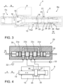
- Figure 3 discloses a rock drilling machine 4 comprising a body 10, an impact device 8, a rotating device 9, a flushing housing 16, an open space 17 for receiving a shank adaptor, and a gear housing 18.
- the flushing housing 16 and gear housing 18 are located at a front end Fe of the body 10, whereas the impact device 8 is located at a rear end Re.
- the shank adapter can be mounted to the open space 17 and its rear end can be connected to rotating elements at the gear housing 18 so that the shank adapter and a drilling tool connectable to the shank adapter can be rotated by means of the rotating device 9.
- Flushing fluid can be fed via the flushing housing 16 to an axial flushing channel of the shank adapter and further to the drilling tool.
- the impact device 8 comprises a percussion piston 19 which is arranged to move in a reciprocating manner in the impact direction A and return direction B. At a front end of the percussion piston 19 is an impact surface 20 which is configured to strike the shank adapter.
- the impact device 8 may comprise a percussion cartridge 21 which is arranged axially inside a rear portion Re2 of a central space 22 of the body 10.
- the percussion cartridge 21 may comprise a valve cylinder 23 through which the percussion piston 19 passes.
- the impact device 8 comprises a working pressure space 24 provided with hydraulic pressure fluid for moving the percussion piston 19 in the reverse direction B. There is a control pressure space 25 at a rear end Re2 of the valve cylinder 23.
- the control pressure space 25 is provided with a sleeve-like control valve 26 for controlling hydraulic pressure affecting at the control pressure space 25 and to thereby control reciprocating movement of the percussion piston 19.
- the pressure in the control valve space 25 moves the percussion piston 19 in the impact direction because working pressure areas of the percussion piston in the impact direction A are greater therein compared to working pressure areas or the percussion piston at the working pressure space 24 and affecting in the return direction B.
- the working pressure space 24 there may prevail continuous high pressure during the operation, whereas in the control pressure space 25 magnitude of the pressure can be changed by means of the control valve 26 for making the percussion piston 19 to execute the reciprocating movement.
- valve cylinder 23 is provided with a pilot pressure space 27 for providing pressure pulses in response to movement of the percussion piston 19 in the impact direction A.
- the valve cylinder 23 is further provided with several axial fluid channels 28 for connecting the pilot pressure space 27 and the control pressure space 25. The pressure pulses generated in the pilot pressure space 27 effect on control surfaces of the control valve 26 and make it to change its control position.
- the control valve 26 is an elongated piece with a central axis and radial outer and inner surfaces, and it comprises several control surfaces at axial distances from each other for controlling hydraulic fluid flows in response to axial control movement. Furthermore, one or more radial surfaces i.e., inner or outer surfaces, of the control valve 26 comprise one or several slanted surfaces longitudinal direction of which have oblique orientation in relation to the central axis of the control valve. Possible configurations of the slanted surfaces are disclosed in Figures 5-17 .
- the impact device 8 disclosed in Figure 3 may be utilized also in a rock breaking hammer. Then there is no rotating device, gearing housing, flushing housing and the shank adapter.
- the percussion piston may be arranged to strike to an impact surface of a breaking tool.
- FIG. 4 discloses in a simplified view another type of an impact device 8 and a valve system for controlling reciprocating operation of a percussion piston 19.
- the valve system comprises a spool valve 29 provided with an elongated shaft-like control valve 26 which is arranged axially movably inside a valve housing 30.
- the control valve 26 comprises several control surfaces 31a - 31d at axial distances from each other for controlling hydraulic fluid flows in response to the axial control movement M.
- the control valve 26 can open and close connections between a tank 32, hydraulic pump 33, a first working pressure space 34 of the impact device 8, and a second working pressure space 35 of the impact device 8 to thereby control the movement of the percussion piston 19 in impact direction A and return direction B.
- one or more radial outer surfaces of the control valve 26 comprises one or several slanted surfaces longitudinal direction of which have oblique orientation in relation to the central axis of the control valve 26. Possible configurations of the slanted surfaces on the control valve 26 are disclosed in Figures 18 - 21 .
- control valve 26 is alternating pressure prevailing in working pressures spaces 34 and 35, but in an alternative solution the pressure may be changed only in one working pressure space when working pressure areas are dimensioned accordingly.
- Figure 5 and 6 disclose a control valve 26 which is a control sleeve 38 comprising central axis Ca and a central axial opening 39 configured to serve as a fluid passage.
- the control sleeve 38 has radial outer surfaces Ros and radial inner surfaces Ris.
- the control valve 26 has a control shoulder 40 on the radial outer surface Ros.
- the control shoulder 40 is provided with several slanted surfaces SS.
- the slanted surfaces SS have groove-like configuration.
- torque T is generated and the control sleeve 38 can turn.
- Direction of the hydraulic fluid flow Hff is indicated by an arrow.
- Figure 6 shows that the slanted surfaces 40 have continuously changing radial dimensions. This can be noted since the slanted surfaces have wider left side edge 41 which narrows towards a right side edge 42.
- Figures 7 and 8 disclose a control valve 26 which is a control sleeve 38 and comprises slanted surfaces SS on its radial inner surfaces Ris.
- the slanted surfaces SS are grooves and have helical configuration in longitudinal direction of the slanted surface SS.
- Figures 9 and 10 disclose a control sleeve 38 which differs from the one shown in Figures 7 and 8 in that number of the slanted surfaces SS, i.e., the number of the helical grooves on the radial inner surfaces is greater.
- control sleeves 38 have first end surfaces 43 and opposite second end surfaces 44, and the helical grooves extend from end the end in Figures 7 - 10 . Then surface areas of the slanted surfaces SS are great and effective torque T can be generated.
- the grooves forming the slanted surfaces SS may have constant depth, as it is shown in Figures 7 - 11 .
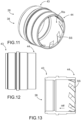
- Figures 11 - 13 disclose a control sleeve 38 which is provided with several slanted surfaces SS on its radial inner surfaces Ris at second end surfaces 44.
- Figures 14 and 15 disclose a control sleeve 38 which is provided with several slanted surfaces SS on its radial inner surfaces Ris at first end surfaces 44.
- shape of groove-like slanted surfaces SS vary continuously in their length direction. In other words, width and depth of the grooves diminish towards the second end 43.
- Figures 16 and 17 disclose a control sleeve 38 which is provided with several slanted surfaces SS on an inner control shoulder 45.
- Figures 18 and 19 disclose a shaft-like control valve 26 of a spool valve.
- the slanted surfaces SS may be grooves cross-section of which change along their length.
- the slanted surfaces SS are arranged at sections where occurs hydraulic fluid flow Hff which makes the control valve 26 turn by the help of the slanted surfaces SS.
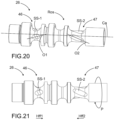
- Figures 20 and 21 also disclose a shaft-like control valve 26 of a spool valve.
- the control valve 26 differs from the one shown in Figures 18 and 19 in that there are a first set 46 of several first slanted surfaces SS-1 and a second set 47 of several second slanted surfaces SS-2 at an axial distance from the first set SS-1.
- the first and second slanted surfaces SS-1, SS-2 have oppositely directed oblique orientations 01, O2 relative to each other.
- the control valve 26 can control fluid flows having opposite flow directions Hff1, Hff2 relative to each other.
- first set 46 is influenced by first fluid flow Hff1 having first direction of flow
- second set 47 is influenced by second fluid flow Hff2 having second direction.
- the first and second sets 46, 47 are configured to turn P the control valve 26 to the same rotation direction when being influenced by the first and second fluid flows Hff1, Hff2.
- Figures 20 and 21 also show, that the control valve 26 may comprise slanted surfaces SS-1 and SS-2 which have different shapes and dimensions.
Landscapes
- Engineering & Computer Science (AREA)
- Mechanical Engineering (AREA)
- General Engineering & Computer Science (AREA)
- Physics & Mathematics (AREA)
- Fluid Mechanics (AREA)
- Earth Drilling (AREA)
- Percussive Tools And Related Accessories (AREA)
- Crushing And Pulverization Processes (AREA)
- Operation Control Of Excavators (AREA)
- Valve Housings (AREA)
Priority Applications (11)
| Application Number | Priority Date | Filing Date | Title |
|---|---|---|---|
| EP22168155.4A EP4261441A1 (de) | 2022-04-13 | 2022-04-13 | Steuerventil, schlagvorrichtung und verfahren |
| JP2024559875A JP7727129B2 (ja) | 2022-04-13 | 2023-04-06 | 制御バルブおよび衝撃装置 |
| CA3246470A CA3246470A1 (en) | 2022-04-13 | 2023-04-06 | CONTROL VALVE AND IMPACT DEVICE |
| AU2023253104A AU2023253104B2 (en) | 2022-04-13 | 2023-04-06 | Control valve and impact device |
| PE2024002211A PE20250229A1 (es) | 2022-04-13 | 2023-04-06 | Valvula de control y dispositivo de impacto |
| US18/855,477 US20250187166A1 (en) | 2022-04-13 | 2023-04-06 | Control valve and impact device |
| CN202380033091.6A CN118974458A (zh) | 2022-04-13 | 2023-04-06 | 控制阀和冲击装置 |
| PCT/EP2023/059116 WO2023198585A1 (en) | 2022-04-13 | 2023-04-06 | Control valve and impact device |
| KR1020247033311A KR102758839B1 (ko) | 2022-04-13 | 2023-04-06 | 제어 밸브 및 충격 디바이스 |
| CL2024003049A CL2024003049A1 (es) | 2022-04-13 | 2024-10-08 | Válvula de control y dispositivo de impacto. |
| MX2024012646A MX2024012646A (es) | 2022-04-13 | 2024-10-11 | Valvula de control y dispositivo de impacto |
Applications Claiming Priority (1)
| Application Number | Priority Date | Filing Date | Title |
|---|---|---|---|
| EP22168155.4A EP4261441A1 (de) | 2022-04-13 | 2022-04-13 | Steuerventil, schlagvorrichtung und verfahren |
Publications (1)
| Publication Number | Publication Date |
|---|---|
| EP4261441A1 true EP4261441A1 (de) | 2023-10-18 |
Family
ID=81603497
Family Applications (1)
| Application Number | Title | Priority Date | Filing Date |
|---|---|---|---|
| EP22168155.4A Pending EP4261441A1 (de) | 2022-04-13 | 2022-04-13 | Steuerventil, schlagvorrichtung und verfahren |
Country Status (11)
| Country | Link |
|---|---|
| US (1) | US20250187166A1 (de) |
| EP (1) | EP4261441A1 (de) |
| JP (1) | JP7727129B2 (de) |
| KR (1) | KR102758839B1 (de) |
| CN (1) | CN118974458A (de) |
| AU (1) | AU2023253104B2 (de) |
| CA (1) | CA3246470A1 (de) |
| CL (1) | CL2024003049A1 (de) |
| MX (1) | MX2024012646A (de) |
| PE (1) | PE20250229A1 (de) |
| WO (1) | WO2023198585A1 (de) |
Citations (7)
| Publication number | Priority date | Publication date | Assignee | Title |
|---|---|---|---|---|
| US3051191A (en) * | 1958-06-11 | 1962-08-28 | Daimler Benz Ag | Pressure regulating slide valve, especially for automatic control mechanisms for shifting the gears of motor vehicles |
| US3807454A (en) * | 1972-12-15 | 1974-04-30 | Gen Signal Corp | Low effort plunger |
| DE102005030173A1 (de) * | 2005-06-29 | 2007-01-04 | Bosch Rexroth Aktiengesellschaft | Ventilkolben und Herstellungsverfahren für einen Ventilkolben |
| US20070151614A1 (en) * | 2005-12-29 | 2007-07-05 | Dayton Robert A | Pressure regulating valve |
| US20180163888A1 (en) * | 2016-05-31 | 2018-06-14 | Komatsu Ltd. | Spool valve, operation device, and work vehicle |
| EP2906323B1 (de) * | 2012-10-11 | 2019-04-17 | 3M Innovative Properties Company | Wasser-auf-wasser-umkehrosmosesteuerventil |
| EP3919717A1 (de) * | 2020-06-01 | 2021-12-08 | Sandvik Mining and Construction Oy | Kolbenführungselement, gesteinsbohrmaschine und verfahren |
Family Cites Families (14)
| Publication number | Priority date | Publication date | Assignee | Title |
|---|---|---|---|---|
| US6279651B1 (en) * | 1999-07-20 | 2001-08-28 | Halliburton Energy Services, Inc. | Tool for managing fluid flow in a well |
| US6554074B2 (en) * | 2001-03-05 | 2003-04-29 | Halliburton Energy Services, Inc. | Lift fluid driven downhole electrical generator and method for use of the same |
| FI119398B (fi) * | 2006-12-21 | 2008-10-31 | Sandvik Mining & Constr Oy | Iskulaite |
| US7537051B1 (en) * | 2008-01-29 | 2009-05-26 | Hall David R | Downhole power generation assembly |
| NO338554B1 (no) * | 2009-07-03 | 2016-09-05 | Sinvent As | Generator for elektrisk kraft |
| FI123187B (fi) * | 2011-06-07 | 2012-12-14 | Sandvik Mining & Constr Oy | Kallionrikkomislaitteen iskulaite, menetelmä iskulaitteen ohjaamiseksi |
| FI123189B (fi) * | 2011-06-07 | 2012-12-14 | Sandvik Mining & Constr Oy | Kallionrikkomislaitteen iskulaite ja menetelmä iskulaitteen ohjaamiseksi |
| EP2963229B1 (de) * | 2014-07-03 | 2017-05-31 | Sandvik Mining and Construction Oy | Regelventil |
| JP6652008B2 (ja) * | 2016-07-21 | 2020-02-19 | 株式会社デンソー | スプール弁 |
| AU2016423788B2 (en) * | 2016-09-23 | 2021-11-04 | Halliburton Energy Services, Inc. | Systems and methods for controlling fluid flow in a wellbore using a switchable downhole crossover tool with rotatable sleeve |
| CA3034607A1 (en) * | 2016-10-06 | 2018-04-12 | Halliburton Energy Services, Inc. | A flow control system for power generation |
| ES2888936T3 (es) * | 2017-06-02 | 2022-01-10 | Sandvik Intellectual Property | Máquina de perforación en fondo y método para perforar roca |
| US11352844B2 (en) * | 2020-07-01 | 2022-06-07 | Workover Solutions, Inc. | Flow rate control system and method |
| JPWO2022097515A1 (de) * | 2020-11-05 | 2022-05-12 |
-
2022
- 2022-04-13 EP EP22168155.4A patent/EP4261441A1/de active Pending
-
2023
- 2023-04-06 AU AU2023253104A patent/AU2023253104B2/en active Active
- 2023-04-06 US US18/855,477 patent/US20250187166A1/en active Pending
- 2023-04-06 JP JP2024559875A patent/JP7727129B2/ja active Active
- 2023-04-06 PE PE2024002211A patent/PE20250229A1/es unknown
- 2023-04-06 WO PCT/EP2023/059116 patent/WO2023198585A1/en not_active Ceased
- 2023-04-06 CN CN202380033091.6A patent/CN118974458A/zh active Pending
- 2023-04-06 CA CA3246470A patent/CA3246470A1/en active Pending
- 2023-04-06 KR KR1020247033311A patent/KR102758839B1/ko active Active
-
2024
- 2024-10-08 CL CL2024003049A patent/CL2024003049A1/es unknown
- 2024-10-11 MX MX2024012646A patent/MX2024012646A/es unknown
Patent Citations (7)
| Publication number | Priority date | Publication date | Assignee | Title |
|---|---|---|---|---|
| US3051191A (en) * | 1958-06-11 | 1962-08-28 | Daimler Benz Ag | Pressure regulating slide valve, especially for automatic control mechanisms for shifting the gears of motor vehicles |
| US3807454A (en) * | 1972-12-15 | 1974-04-30 | Gen Signal Corp | Low effort plunger |
| DE102005030173A1 (de) * | 2005-06-29 | 2007-01-04 | Bosch Rexroth Aktiengesellschaft | Ventilkolben und Herstellungsverfahren für einen Ventilkolben |
| US20070151614A1 (en) * | 2005-12-29 | 2007-07-05 | Dayton Robert A | Pressure regulating valve |
| EP2906323B1 (de) * | 2012-10-11 | 2019-04-17 | 3M Innovative Properties Company | Wasser-auf-wasser-umkehrosmosesteuerventil |
| US20180163888A1 (en) * | 2016-05-31 | 2018-06-14 | Komatsu Ltd. | Spool valve, operation device, and work vehicle |
| EP3919717A1 (de) * | 2020-06-01 | 2021-12-08 | Sandvik Mining and Construction Oy | Kolbenführungselement, gesteinsbohrmaschine und verfahren |
Also Published As
| Publication number | Publication date |
|---|---|
| KR102758839B1 (ko) | 2025-01-22 |
| US20250187166A1 (en) | 2025-06-12 |
| AU2023253104B2 (en) | 2025-06-26 |
| JP7727129B2 (ja) | 2025-08-20 |
| CL2024003049A1 (es) | 2025-02-21 |
| WO2023198585A1 (en) | 2023-10-19 |
| CA3246470A1 (en) | 2023-10-19 |
| MX2024012646A (es) | 2024-11-08 |
| KR20240152944A (ko) | 2024-10-22 |
| JP2025512344A (ja) | 2025-04-17 |
| CN118974458A (zh) | 2024-11-15 |
| PE20250229A1 (es) | 2025-01-28 |
| AU2023253104A1 (en) | 2024-10-31 |
Similar Documents
| Publication | Publication Date | Title |
|---|---|---|
| EP3409878A1 (de) | Imlochbohrmaschine und verfahren zum bohren von gestein | |
| CN101370621A (zh) | 冲击装置和包括这种冲击装置的凿岩机 | |
| CN113631793B (zh) | 用于冲击钻凿的岩钻头 | |
| EP1590551B1 (de) | Hydraulisches system für bergbauausrüstung und verfahren zum einstellen der leistung einer gesteinsbohrmaschine | |
| JP2020528504A (ja) | 脱着式ビットヘッド付きドリルビット | |
| US20250187166A1 (en) | Control valve and impact device | |
| CN112969838A (zh) | 潜孔锤钻头组件 | |
| CA2550801C (en) | Drilling equipment | |
| US7055633B2 (en) | Concrete drill | |
| US12404725B2 (en) | Valve cylinder, impact device and method | |
| EP1488071B1 (de) | Verfahren und vorrichtung zum richtungsbohren von bohrlöchern | |
| CA3236845C (en) | Valve cylinder, impact device and method | |
| RU2015288C1 (ru) | Устройство для изменения траектории ствола скважины | |
| US3547006A (en) | Variable stroke percussion tool | |
| EP4386174B1 (de) | Drehhülse, gesteinsbohrmaschine und verfahren | |
| EP2987945B1 (de) | Hydraulischer schlaghammer | |
| CN112443467B (zh) | 缸体、液压装置、施工机械、缸体的制造方法 | |
| RU2169822C1 (ru) | Шарошечный расширитель | |
| RU2323320C1 (ru) | Регулируемое отклоняющее устройство | |
| CN114427343A (zh) | 一种液力扭转冲击器防死区启动装置 | |
| PL100440B1 (pl) | Urzadzenie z napedem hydraulicznym do wiercenia skal | |
| DD262060A1 (de) | Druckfluessigkeitsgetriebener bohrhammerschlagkolben |
Legal Events
| Date | Code | Title | Description |
|---|---|---|---|
| PUAI | Public reference made under article 153(3) epc to a published international application that has entered the european phase |
Free format text: ORIGINAL CODE: 0009012 |
|
| STAA | Information on the status of an ep patent application or granted ep patent |
Free format text: STATUS: THE APPLICATION HAS BEEN PUBLISHED |
|
| AK | Designated contracting states |
Kind code of ref document: A1 Designated state(s): AL AT BE BG CH CY CZ DE DK EE ES FI FR GB GR HR HU IE IS IT LI LT LU LV MC MK MT NL NO PL PT RO RS SE SI SK SM TR |
|
| STAA | Information on the status of an ep patent application or granted ep patent |
Free format text: STATUS: REQUEST FOR EXAMINATION WAS MADE |
|
| 17P | Request for examination filed |
Effective date: 20240418 |
|
| RBV | Designated contracting states (corrected) |
Designated state(s): AL AT BE BG CH CY CZ DE DK EE ES FI FR GB GR HR HU IE IS IT LI LT LU LV MC MK MT NL NO PL PT RO RS SE SI SK SM TR |