EP4261463A2 - Kochgerät - Google Patents
Kochgerät Download PDFInfo
- Publication number
- EP4261463A2 EP4261463A2 EP23195765.5A EP23195765A EP4261463A2 EP 4261463 A2 EP4261463 A2 EP 4261463A2 EP 23195765 A EP23195765 A EP 23195765A EP 4261463 A2 EP4261463 A2 EP 4261463A2
- Authority
- EP
- European Patent Office
- Prior art keywords
- steam
- water
- cooking
- heater
- controller
- Prior art date
- Legal status (The legal status is an assumption and is not a legal conclusion. Google has not performed a legal analysis and makes no representation as to the accuracy of the status listed.)
- Pending
Links
Images


Classifications
-
- A—HUMAN NECESSITIES
- A47—FURNITURE; DOMESTIC ARTICLES OR APPLIANCES; COFFEE MILLS; SPICE MILLS; SUCTION CLEANERS IN GENERAL
- A47J—KITCHEN EQUIPMENT; COFFEE MILLS; SPICE MILLS; APPARATUS FOR MAKING BEVERAGES
- A47J27/00—Cooking-vessels
- A47J27/04—Cooking-vessels for cooking food in steam; Devices for extracting fruit juice by means of steam ; Vacuum cooking vessels
-
- F—MECHANICAL ENGINEERING; LIGHTING; HEATING; WEAPONS; BLASTING
- F24—HEATING; RANGES; VENTILATING
- F24C—DOMESTIC STOVES OR RANGES ; DETAILS OF DOMESTIC STOVES OR RANGES, OF GENERAL APPLICATION
- F24C15/00—Details
- F24C15/32—Arrangements of ducts for hot gases, e.g. in or around baking ovens
- F24C15/322—Arrangements of ducts for hot gases, e.g. in or around baking ovens with forced circulation
- F24C15/327—Arrangements of ducts for hot gases, e.g. in or around baking ovens with forced circulation with air moisturising
-
- A—HUMAN NECESSITIES
- A47—FURNITURE; DOMESTIC ARTICLES OR APPLIANCES; COFFEE MILLS; SPICE MILLS; SUCTION CLEANERS IN GENERAL
- A47J—KITCHEN EQUIPMENT; COFFEE MILLS; SPICE MILLS; APPARATUS FOR MAKING BEVERAGES
- A47J27/00—Cooking-vessels
- A47J27/56—Preventing boiling over, e.g. of milk
- A47J27/62—Preventing boiling over, e.g. of milk by devices for automatically controlling the heat supply by switching off heaters or for automatically lifting the cooking-vessels
-
- A—HUMAN NECESSITIES
- A47—FURNITURE; DOMESTIC ARTICLES OR APPLIANCES; COFFEE MILLS; SPICE MILLS; SUCTION CLEANERS IN GENERAL
- A47J—KITCHEN EQUIPMENT; COFFEE MILLS; SPICE MILLS; APPARATUS FOR MAKING BEVERAGES
- A47J36/00—Parts, details or accessories of cooking-vessels
- A47J36/24—Warming devices
- A47J36/2405—Warming devices for warming food contained in vessels immersed in a water bath, e.g. chafers or steam tables
-
- A—HUMAN NECESSITIES
- A47—FURNITURE; DOMESTIC ARTICLES OR APPLIANCES; COFFEE MILLS; SPICE MILLS; SUCTION CLEANERS IN GENERAL
- A47J—KITCHEN EQUIPMENT; COFFEE MILLS; SPICE MILLS; APPARATUS FOR MAKING BEVERAGES
- A47J36/00—Parts, details or accessories of cooking-vessels
- A47J36/32—Time-controlled igniting mechanisms or alarm devices
-
- F—MECHANICAL ENGINEERING; LIGHTING; HEATING; WEAPONS; BLASTING
- F24—HEATING; RANGES; VENTILATING
- F24C—DOMESTIC STOVES OR RANGES ; DETAILS OF DOMESTIC STOVES OR RANGES, OF GENERAL APPLICATION
- F24C7/00—Stoves or ranges heated by electric energy
- F24C7/08—Arrangement or mounting of control or safety devices
- F24C7/087—Arrangement or mounting of control or safety devices of electric circuits regulating heat
-
- A—HUMAN NECESSITIES
- A47—FURNITURE; DOMESTIC ARTICLES OR APPLIANCES; COFFEE MILLS; SPICE MILLS; SUCTION CLEANERS IN GENERAL
- A47J—KITCHEN EQUIPMENT; COFFEE MILLS; SPICE MILLS; APPARATUS FOR MAKING BEVERAGES
- A47J27/00—Cooking-vessels
- A47J27/04—Cooking-vessels for cooking food in steam; Devices for extracting fruit juice by means of steam ; Vacuum cooking vessels
- A47J2027/043—Cooking-vessels for cooking food in steam; Devices for extracting fruit juice by means of steam ; Vacuum cooking vessels for cooking food in steam
Definitions
- the present specification relates to a cooking appliance and a method for controlling the same.
- the cooking appliance refers to an appliance for cooking food using heat of a heating source.
- the cooking appliance may include a heating source for heating food contained in a cooking chamber.
- the cooking appliance may include at least one or plurality of heating sources. If the cooking appliance includes a steam generator, steam generated in the steam generator is supplied to a cooking chamber, thereby cooking food.
- Korean Patent Registration Publication No. 10-0624080 discloses a heating cooker including a main body having a cooking chamber formed therein, a steam generation heater installed in the cooking chamber, a water receiver installed in the cooking chamber such that a portion of the steam generation heater is submerged, and a water supply device for supplying water to the water receiver.
- the water in the water receiver is evaporated by residual heat of the steam generation heater, such that residual water does not remain in the water receiver.
- the present embodiment provides a cooking appliance capable of changing water dropping to the bottom of a cooking chamber into steam used for cooking in a steam cooking process, and a method for controlling the same.
- the present embodiment provides a cooking appliance capable of increasing the amount of steam used to cook food to enable rapid cooking, and a method for controlling the same.
- the present embodiment provides a cooking appliance, in which residual water does not remain on the bottom of a cooking chamber after steam cooking is finished, and a method for controlling the same.
- a cooking appliance includes a main body including a cooking chamber, a steam generator including a steam heater for generating steam for heating food contained in the cooking chamber, a lower heater located below a bottom wall of the cooking chamber and configured to generate heat to heat the food, and a controller configured to control the steam heater and the lower heater.
- the controller operates the steam heater to generate steam when a steam cooking mode is selected, and turns the lower heater on while steam cooking is performed.
- a recessed water collection part for collecting water may be provided in the bottom wall of the cooking chamber, such that condensed water dropping the bottom wall of the cooking chamber is efficiently changed into steam.
- the lower heater may be turned on when a predetermined time has passed after the steam cooking starts.
- the cooking appliance may comprise a steam supply port provided in one sidewall of the cooking chamber.
- the cooking appliance may comprise a water tank configured to store water for generating steam to be supplied to the cooking chamber.
- the cooking appliance may comprise a water supply pump configured to supply water to the water tank.
- the cooking appliance may comprise a drainage pump for discharging water of the water tank.
- a cooking appliance includes a main body including a cooking chamber, a steam supply port provided in one sidewall of the cooking chamber, a water tank configured to store water used to generate steam to be supplied to the cooking chamber, a steam generator including a steam heater for heating water stored in the water tank, a water supply pump configured to supply water to the water tank, a lower heater located below a bottom wall of the cooking chamber and configured to generate heat to heat the food, and a controller configured to control the steam heater and the lower heater.
- the controller operates the water supply pump such that water supplied to the water tank is supplied to the cooking chamber through the steam support port before the steam heater operates, when a steam cooking mode is selected, and operates the steam heater and the lower heater after water is supplied to the cooking chamber.
- a water collection part for collecting water used to generate steam may be provided in the bottom wall of the cooking chamber.
- the steam generator including the water tank and the steam heater are disposed outside the cooking chamber.
- the steam generator preferably the water tank, is connected by a channel to the steam support port being preferably provided at a wall of the cooking chamber.
- the lower heater may be turned off after operating for a predetermined time.
- the lower heater may be turned on again once or more until the steam cooking is finished, after the lower heater is turned off, such that residual water does not remain in the water collection part.
- a method for controlling a cooking appliance includes starting steam cooking and operating a steam heater for generating steam to be supplied to a cooking chamber, determining whether a predetermined time has passed after the steam cooking starts, and turning a lower heater provided below a bottom wall of the cooking chamber on upon determining that the predetermined time has passed.
- a method for controlling a cooking appliance including a water tank configured to store water used to generate steam to be supplied to a cooking chamber, a steam generator including a steam heater for heating water stored in the water tank, a water supply pump configured to supply water to the water tank, a lower heater located below a bottom wall of the cooking chamber, and a steam supply port provided in one sidewall of the cooking chamber to supply the steam generated in the water tank includes starting steam cooking and operating the water supply pump such that water passing through the water thank is supplied to the cooking chamber through the steam supply port, operating a drainage pump to discharge some of the water of the water tank after operating the water supply pump, and simultaneously or sequentially operating the steam heater and the lower heater after stopping the drainage pump.
- first, second, A, B, (a) and (b) may be used.
- Each of the terms is merely used to distinguish the corresponding component from other components, and does not delimit an essence, an order or a sequence of the corresponding component. It should be understood that when one component is “connected”, “coupled” or “joined” to another component, the former may be directly connected or jointed to the latter or may be “connected”, coupled” or “joined” to the latter with a third component interposed therebetween.
- FIG. 1 is a view schematically showing a cooking appliance according to an embodiment of the present invention
- FIG. 2 is a block diagram showing a cooking appliance according to an embodiment of the present invention.
- the cooking appliance 1 may include a main body 10.
- the main body 10 may include a cooking chamber 12.
- the cooking appliance 1 may further include a door connected to the main body 10 to open or close the cooking chamber 12.
- the cooking appliance 1 may include at least one or a plurality of heating sources in order to cook the food contained in the cooking chamber 12.
- the heating source may include an electric heater, a magnetron, a steam generator, etc. or a combination thereof.
- the plurality of heating sources may include, for example, an upper heater 21 and a lower heater 22.
- the upper heater 21 may be located at the upper side in the cooking chamber 12 and may supply heat to the upper space of the cooking chamber 12.
- the upper heater 21 may be located at the upper side of the cooking chamber 12, preferably outside the cooking chamber 12. In this case, an opening, through which heat passes, may be formed in the upper wall of the cooking chamber 12.
- a transmission part may be provided in the upper wall of the cooking chamber 12.
- the lower heater 22 may be located below the bottom wall 12a of the cooking chamber 12 outside the cooking chamber 12. The lower heater 22 may supply heat to the lower side of the food contained in the cooking chamber 12.
- a water collection part 12b in which water may be collected, may be provided in the bottom wall 12a of the cooking chamber 12.
- the water collection part 12b may be, for example, formed in the bottom wall 12a in a downwardly recessed shape.
- Water collected in the water collection part 12b may be heated by the lower heater 22, thereby being evaporated.
- the upper heater 21 and the lower heater 22 may be, for example, electric heater.
- the plurality of heating sources may further include a convection heater 25 configuring a convection device 24.
- the convection device 24 may include a convection fan. By the convection fan, air in the cooking chamber 21 may flow to the convection heater, thereby being heated and then supplied to the cooking chamber 12.
- the plurality of heating sources may further include a steam generator 30 for heating water to generate steam.
- the steam generator 30 may include a water tank for storing water and a steam heater 31 for heating the water of the water tank.
- the water When water is heated by the steam heater 31, the water may be changed into steam and the steam may be supplied into the cooking chamber 12 through a steam supply port 33 formed in one sidewall of the cooking chamber 12.
- the cooking appliance 1 may further include a water supply pump 34 for supplying water to the water tank.
- the cooking appliance 1 may further include a drainage pump 35 for discharging the water from the water tank of the steam generator.
- the water supply pump 34 may supply water to the water tank for the steam cooking process. Preferably, during the steam cooking process, the water supply pump 34 may be intermittently operated to intermittently supply water to the water tank.
- the drainage pump 35 may operate to discharge residual water remaining in the water tank after the steam cooking process.
- the cooking appliance 1 may further include an operation unit 41 for selecting a cooking mode or a type of each of the plurality of heating sources and a controller 40 for controlling the plurality of heating sources by a command received from the operation unit 41.
- the cooking appliance 1 may cook various types of food using various cooking modes.
- the cooking mode may include at least a steam cooking mode for cooking food using at least steam.
- At least the steam heater 31 of the plurality of heating sources may operate.
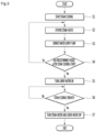
- FIG. 3 is a flowchart illustrating a method of controlling a cooking appliance according to an embodiment of the present invention.
- steam cooking may start (S1).
- the controller 40 operates the steam heater 31 (S2). Although water is not contained in the water tank, the steam heater 31 may first operate, for preheating the water tank.
- controller 40 may operate the water supply pump 34 for supplying water to the water tank (S3).
- the controller 40 may operate the drainage pump 35 for a predetermined time before operating the water supply pump 34, in order to remove water which may remain in the water tank.
- the drainage pump 35 may first operate in order to discharge the scale in the water tank together with residual water.
- the scale may be supplied to the cooking chamber together with steam.
- the scale may be attached to food. However, this may be prevented by operating the drainage pump 35 before operating the water supply pump 34.
- the drainage pump 35 may first operate and then the steam heater 31 may operate.
- the water supply pump 34 and the steam heater 31 may simultaneously operate.
- the water supply pump 34 may first operate to start water supply and then the steam heater 31 may operate.
- the amount of water supplied to the water tank by operation of the water supply pump 34 at the beginning of the steam cooking may be referred to as a first supply amount.
- the first supply amount may be set to a capacity/volume less than a maximum capacity/volume of the water tank. So the water tank is not fully filled up.
- the steam heater 31 When the steam heater 31 operates in a state of supplying water to the water tank, the water of the water tank may be heated and transferred by heat of the steam heater 31 into steam.
- the steam generated in the water tank may be supplied into the cooking chamber 12 through the steam supply port 33.
- the steam heater 31 may be repeatedly turned on and off in the entire steam cooking process. That is, the steam heater 31 may be intermittently operated by the controller 40.
- the water supply pump 34 may also be repeatedly turned on and off in the entire steam cooking process. That is, the water supply pump 34 may be intermittently operated by the controller 40.
- the steam is supplied into the cooking chamber 12 for heating food inside the cooking chamber 12. Some of the steam supplied to the cooking chamber 12 may come in contact with the food. Then the steam is condensed and the condensed water is flowing along the food downwardly.
- the other of the steam supplied into the cooking chamber 12 may not contact the food and may be condensed in the cooking chamber 12, thereby condensed water drops to the bottom wall 12a of the cooking chamber 12.
- the recessed water collection part 12b is provided mainly in the bottom wall 12a of the cooking chamber 12, the condensed water is collected in the water collection part 12b.
- the amount of condensed water collected in the water collection part 12b may be increased.
- the controller 40 may determine whether a predetermined time has passed after the steam cooking starts (S4).
- step S4 Upon determining that the predetermined time has passed after the steam cooking starts in step S4, the controller 40 turns the lower heater 22 on (S5).
- Such steam may be used to heat the food.
- the food may be cooked by the steam generated in the steam generator 30 in the steam cooking process and the steam generated by heating the water collected in the water collection part 12b.
- the controller 40 determines whether steam cooking is finished (S6), and turns off the steam heater 31 and the upper heater 22 when steam cooking is finished (S7).
- the amount of water collected in the water collection part 12b at the beginning of the steam cooking is small, the amount of steam generated by operating the lower heater 22 is small and thus the food may be excessively heated by heat of the lower heater 22.
- the lower heater 22 is turned on only when the predetermined time has passed after the steam cooking starts. So, an excessive heating of the food by the lower heater is avoided.
- the lower heater 22 is turned off after the steam cooking is finished in the above embodiment, the lower heater 22 may be turned off before the steam cooking is finished.
- the lower heater 22 may intermittently operate until the steam cooking is finished. That is, the lower heater 22 may be repeatedly turned on/off.
- FIG. 4 is a flowchart illustrating a method of controlling a cooking appliance according to another embodiment of the present invention.
- the present embodiment is equal to the previous embodiment in the configuration of the cooking appliance and is different therefrom in a method for generating additional steam by the lower heater. Accordingly, only the characteristics of the present embodiment will be described.
- steam cooking may start (S11).
- the controller 40 may operate the water supply pump 34 such that water is supplied to the water collection part 12b before the steam heater 31 operates (S12).
- the amount of water supplied to the water tank by the water supply pump 34 may be referred to as a second supply amount.
- the second supply amount of water may be greater than the first supply amount of water of the first embodiment. But essentially the second supply amount of water may be greater than the maximum capacity/volume of the water tank, such that the water overflows the water tank and passing through the water tank is supplied into the cooking chamber to be collected in the water collection part 12b.
- the second supply amount may be set to a capacity/volume higher than the maximum capacity/volume of the water tank and preferably also the maximum capacity/volume of a steam channel for connecting the water tank and the steam supply port 33.
- the water supplied to the water tank may overflow from the water tank, thereby being supplied to the cooking chamber 12 through the steam supply port 33.
- the scale since the water supplied to the water tank is supplied to the cooking chamber 12, even when scale is present in the water tank, the scale may be discharged from the water tank and moved to the bottom wall 12a of the cooking chamber 12 together with water.
- the user can easily remove the scale present in the water collection part 12b after the cooking is finished.
- the controller 40 stops the water supply pump 34 and may operate the drainage pump 35 (S13).
- the water tank when operation of the water supply pump 34 is stopped, the water tank is filled with water and water remains in the channel for connecting the water tank and the steam support port 33.
- the drainage pump 35 may operate in order to discharge some of the water of the water tank.
- controller 40 controls operation of the steam heater 31 such that the steam heater 31 intermittently operates (S14).
- controller 40 operates the lower heater 22 for a predetermined time such that the water of the water collection part 12 is heated to generate steam, and then turns the lower heater 22 off (S 15).
- the steam heater 31 and the lower heater 22 may simultaneously or sequentially start to operate.
- controller 40 controls the water supply pump 34 such that the water supply pump 34 intermittently operates (S16).
- the lower heater 22 and the steam heater 31 may simultaneously operate in a period of the steam cooking process and only the steam heater 31 may operate in the other period.
- some of the steam generated by the steam generator 30 and supplied to the cooking chamber 12 may be condensed and collected in the water collection part 12b.
- the amount of water collected in the water collection part 12b is less than the amount of water supplied to the water collection part 12b at the beginning of the steam cooking.
- the lower heater 22 operates to heat the water of the water collection part 12, thereby generating steam. Then, the lower heater 22 is stopped after the predetermined time has passed, such that the operation time of the lower heater 22 is prevented from being increased in a state in which water does not remain in the water collection part 12b.
- the condensed water may be collected in the water collection part 12b.
- the controller 40 may control the lower heater 22 such that the lower heater 22 is turned on and off once or more until the steam cooking is finished after the lower heater 22 operates and stops once.
- the controller 40 determines whether the steam cooking is finished (S18), and turns the steam heater 31 off when the steam cooking is finished (S 19).
- the lower heater 22 is turned on again and is turned off before the steam cooking is finished or is turned off together with the steam heater when the steam cooking is finished.
- the lower heater 22 since the lower heater 22 operates in a state of supplying water to the water collection part 12b, the amount of steams used to heat the food in the steam cooking process can be further increased and thus the cooking time of the food can be reduced.
Landscapes
- Engineering & Computer Science (AREA)
- Food Science & Technology (AREA)
- Chemical & Material Sciences (AREA)
- Combustion & Propulsion (AREA)
- Mechanical Engineering (AREA)
- General Engineering & Computer Science (AREA)
- Cookers (AREA)
- Electric Ovens (AREA)
Applications Claiming Priority (2)
| Application Number | Priority Date | Filing Date | Title |
|---|---|---|---|
| KR1020180039202A KR102455063B1 (ko) | 2018-04-04 | 2018-04-04 | 조리기기 및 그의 제어방법 |
| EP18215006.0A EP3550210B1 (de) | 2018-04-04 | 2018-12-21 | Kochgerät mit dampfgenerator und verfahren zur steuerung eines solchen kochgeräts |
Related Parent Applications (1)
| Application Number | Title | Priority Date | Filing Date |
|---|---|---|---|
| EP18215006.0A Division EP3550210B1 (de) | 2018-04-04 | 2018-12-21 | Kochgerät mit dampfgenerator und verfahren zur steuerung eines solchen kochgeräts |
Publications (2)
| Publication Number | Publication Date |
|---|---|
| EP4261463A2 true EP4261463A2 (de) | 2023-10-18 |
| EP4261463A3 EP4261463A3 (de) | 2023-10-25 |
Family
ID=64755349
Family Applications (2)
| Application Number | Title | Priority Date | Filing Date |
|---|---|---|---|
| EP18215006.0A Active EP3550210B1 (de) | 2018-04-04 | 2018-12-21 | Kochgerät mit dampfgenerator und verfahren zur steuerung eines solchen kochgeräts |
| EP23195765.5A Pending EP4261463A3 (de) | 2018-04-04 | 2018-12-21 | Kochgerät |
Family Applications Before (1)
| Application Number | Title | Priority Date | Filing Date |
|---|---|---|---|
| EP18215006.0A Active EP3550210B1 (de) | 2018-04-04 | 2018-12-21 | Kochgerät mit dampfgenerator und verfahren zur steuerung eines solchen kochgeräts |
Country Status (3)
| Country | Link |
|---|---|
| US (1) | US11083321B2 (de) |
| EP (2) | EP3550210B1 (de) |
| KR (1) | KR102455063B1 (de) |
Families Citing this family (3)
| Publication number | Priority date | Publication date | Assignee | Title |
|---|---|---|---|---|
| KR102060356B1 (ko) * | 2018-04-12 | 2019-12-30 | 엘지전자 주식회사 | 조리기기 |
| CN113951741B (zh) * | 2021-12-02 | 2023-03-14 | 深圳市晨北科技有限公司 | 一种烹饪设备及其控制方法 |
| CN117204724A (zh) * | 2023-09-20 | 2023-12-12 | 珠海格力电器股份有限公司 | 烹饪器具的控温方法、装置及烹饪器具 |
Citations (1)
| Publication number | Priority date | Publication date | Assignee | Title |
|---|---|---|---|---|
| KR100624080B1 (ko) | 2003-12-09 | 2006-09-19 | 삼성전자주식회사 | 가열조리장치 |
Family Cites Families (14)
| Publication number | Priority date | Publication date | Assignee | Title |
|---|---|---|---|---|
| US6833032B1 (en) * | 2002-11-05 | 2004-12-21 | Blodgett Holdings, Inc. | Automatic deliming process |
| KR20050027460A (ko) * | 2003-09-15 | 2005-03-21 | 삼성전자주식회사 | 과열증기 조리장치 및 그 제어방법 |
| KR101132331B1 (ko) * | 2004-07-14 | 2012-04-05 | 삼성전자주식회사 | 가열조리장치 및 그 제어방법 |
| KR20060006472A (ko) * | 2004-07-16 | 2006-01-19 | 삼성전자주식회사 | 가열조리장치 |
| JP4311688B2 (ja) * | 2006-11-02 | 2009-08-12 | シャープ株式会社 | 排気蒸気希釈装置及びこれを備えた加熱調理器 |
| US8207477B2 (en) * | 2007-11-26 | 2012-06-26 | Whirlpool Corporation | Method for cooking vegetables using steam |
| US20090136640A1 (en) * | 2007-11-26 | 2009-05-28 | Whirlpool Corporation | Method for Baking a Casserole Using Steam |
| CN106574789B (zh) * | 2014-09-04 | 2020-04-24 | 伊莱克斯家用电器股份公司 | 带有整合的水蒸发器的家用烤箱 |
| JP6579301B2 (ja) * | 2014-10-10 | 2019-09-25 | パナソニックIpマネジメント株式会社 | 加熱調理器 |
| CA2973550C (en) * | 2015-01-23 | 2023-09-26 | Balmuda Inc. | Heating cooker |
| US10969118B2 (en) * | 2016-05-26 | 2021-04-06 | Electrolux Home Products, Inc. | Steam cooking appliance |
| CN109642732B (zh) * | 2016-08-29 | 2020-08-25 | 夏普株式会社 | 加热烹调器 |
| DE102016121306B3 (de) | 2016-11-08 | 2017-11-30 | Miele & Cie. Kg | Haushaltgerät und Elektrisches Heizelement zur Verwendung in einem Haushaltgerät |
| KR102357903B1 (ko) * | 2017-05-19 | 2022-02-03 | 삼성전자주식회사 | 조리기기의 제어 방법 |
-
2018
- 2018-04-04 KR KR1020180039202A patent/KR102455063B1/ko active Active
- 2018-12-21 EP EP18215006.0A patent/EP3550210B1/de active Active
- 2018-12-21 EP EP23195765.5A patent/EP4261463A3/de active Pending
-
2019
- 2019-02-06 US US16/269,170 patent/US11083321B2/en active Active
Patent Citations (1)
| Publication number | Priority date | Publication date | Assignee | Title |
|---|---|---|---|---|
| KR100624080B1 (ko) | 2003-12-09 | 2006-09-19 | 삼성전자주식회사 | 가열조리장치 |
Also Published As
| Publication number | Publication date |
|---|---|
| EP3550210B1 (de) | 2023-09-27 |
| EP4261463A3 (de) | 2023-10-25 |
| KR102455063B1 (ko) | 2022-10-14 |
| US20190307281A1 (en) | 2019-10-10 |
| EP3550210A1 (de) | 2019-10-09 |
| KR20190115919A (ko) | 2019-10-14 |
| US11083321B2 (en) | 2021-08-10 |
Similar Documents
| Publication | Publication Date | Title |
|---|---|---|
| JP4409612B1 (ja) | 加熱調理器 | |
| US20120017769A1 (en) | Cooking apparatus | |
| CN103375826B (zh) | 多功能烹饪设备 | |
| EP4063739B1 (de) | Steuerverfahren für eine kochvorrichtung | |
| EP3550210B1 (de) | Kochgerät mit dampfgenerator und verfahren zur steuerung eines solchen kochgeräts | |
| CN100456895C (zh) | 具有蒸汽发生功能的高频加热装置及其供水控制方法 | |
| JP2004093126A (ja) | トースタ付電子レンジ及びその駆動方法 | |
| JP4875939B2 (ja) | 誘導加熱調理器 | |
| JP2008185293A (ja) | 加熱調理器 | |
| KR20100112965A (ko) | 조리기기의 제어방법 | |
| JP5702876B2 (ja) | 加熱調理器 | |
| JP5542525B2 (ja) | 加熱調理器 | |
| KR101388874B1 (ko) | 조리기기의 제어방법 | |
| JP2002081653A (ja) | 加熱調理器 | |
| JP2007024452A (ja) | 加熱調理器 | |
| CN210891827U (zh) | 集成灶 | |
| KR20080048571A (ko) | 조리 기기 | |
| JP5118378B2 (ja) | 加熱調理器 | |
| JP2008020162A (ja) | 加熱調理器 | |
| JP4987635B2 (ja) | 蒸気調理器 | |
| CN210891828U (zh) | 集成灶 | |
| JP2009210186A (ja) | 加熱調理器 | |
| KR100983275B1 (ko) | 커피 메이커를 구비한 전자레인지 및 그 커피메이커의예약기능 제어방법 | |
| JP2026037023A (ja) | コーヒーメーカー | |
| JP2010266111A (ja) | 加熱調理器 |
Legal Events
| Date | Code | Title | Description |
|---|---|---|---|
| PUAI | Public reference made under article 153(3) epc to a published international application that has entered the european phase |
Free format text: ORIGINAL CODE: 0009012 |
|
| STAA | Information on the status of an ep patent application or granted ep patent |
Free format text: STATUS: REQUEST FOR EXAMINATION WAS MADE |
|
| REG | Reference to a national code |
Ref country code: DE Ref legal event code: R079 Free format text: PREVIOUS MAIN CLASS: F24C0015320000 Ipc: F24C0007080000 |
|
| PUAL | Search report despatched |
Free format text: ORIGINAL CODE: 0009013 |
|
| 17P | Request for examination filed |
Effective date: 20230906 |
|
| AC | Divisional application: reference to earlier application |
Ref document number: 3550210 Country of ref document: EP Kind code of ref document: P |
|
| AK | Designated contracting states |
Kind code of ref document: A2 Designated state(s): AL AT BE BG CH CY CZ DE DK EE ES FI FR GB GR HR HU IE IS IT LI LT LU LV MC MK MT NL NO PL PT RO RS SE SI SK SM TR |
|
| AK | Designated contracting states |
Kind code of ref document: A3 Designated state(s): AL AT BE BG CH CY CZ DE DK EE ES FI FR GB GR HR HU IE IS IT LI LT LU LV MC MK MT NL NO PL PT RO RS SE SI SK SM TR |
|
| RIC1 | Information provided on ipc code assigned before grant |
Ipc: A47J 27/04 20060101ALI20230921BHEP Ipc: F24C 15/32 20060101ALI20230921BHEP Ipc: F24C 7/08 20060101AFI20230921BHEP |
|
| REG | Reference to a national code |
Ref country code: DE Ref legal event code: R079 Free format text: PREVIOUS MAIN CLASS: F24C0007080000 Ipc: A47J0036320000 |
|
| GRAP | Despatch of communication of intention to grant a patent |
Free format text: ORIGINAL CODE: EPIDOSNIGR1 |
|
| STAA | Information on the status of an ep patent application or granted ep patent |
Free format text: STATUS: GRANT OF PATENT IS INTENDED |
|
| RIC1 | Information provided on ipc code assigned before grant |
Ipc: A47J 36/32 20060101AFI20251210BHEP Ipc: F24C 7/08 20060101ALI20251210BHEP Ipc: F24C 15/32 20060101ALI20251210BHEP Ipc: A47J 27/04 20060101ALI20251210BHEP |
|
| INTG | Intention to grant announced |
Effective date: 20251223 |
|
| GRAS | Grant fee paid |
Free format text: ORIGINAL CODE: EPIDOSNIGR3 |
|
| GRAJ | Information related to disapproval of communication of intention to grant by the applicant or resumption of examination proceedings by the epo deleted |
Free format text: ORIGINAL CODE: EPIDOSDIGR1 |
|
| GRAL | Information related to payment of fee for publishing/printing deleted |
Free format text: ORIGINAL CODE: EPIDOSDIGR3 |
|
| STAA | Information on the status of an ep patent application or granted ep patent |
Free format text: STATUS: REQUEST FOR EXAMINATION WAS MADE |
|
| RIN1 | Information on inventor provided before grant (corrected) |
Inventor name: JUNG, YOOJIN Inventor name: SIM, HOONSEOB Inventor name: YANG, JAEKYUNG Inventor name: LEE, YONGSOO Inventor name: LIM, HAKJOO |