EP4261473A1 - Puits géothermique, et appareil de tubage correspondant - Google Patents
Puits géothermique, et appareil de tubage correspondant Download PDFInfo
- Publication number
- EP4261473A1 EP4261473A1 EP22315084.8A EP22315084A EP4261473A1 EP 4261473 A1 EP4261473 A1 EP 4261473A1 EP 22315084 A EP22315084 A EP 22315084A EP 4261473 A1 EP4261473 A1 EP 4261473A1
- Authority
- EP
- European Patent Office
- Prior art keywords
- string
- cooling
- working fluid
- insulated tubing
- tubing string
- Prior art date
- Legal status (The legal status is an assumption and is not a legal conclusion. Google has not performed a legal analysis and makes no representation as to the accuracy of the status listed.)
- Pending
Links
Images


Classifications
-
- F—MECHANICAL ENGINEERING; LIGHTING; HEATING; WEAPONS; BLASTING
- F24—HEATING; RANGES; VENTILATING
- F24T—GEOTHERMAL COLLECTORS; GEOTHERMAL SYSTEMS
- F24T10/00—Geothermal collectors
- F24T10/20—Geothermal collectors using underground water as working fluid; using working fluid injected directly into the ground, e.g. using injection wells and recovery wells
-
- F—MECHANICAL ENGINEERING; LIGHTING; HEATING; WEAPONS; BLASTING
- F24—HEATING; RANGES; VENTILATING
- F24T—GEOTHERMAL COLLECTORS; GEOTHERMAL SYSTEMS
- F24T10/00—Geothermal collectors
- F24T2010/50—Component parts, details or accessories
-
- F—MECHANICAL ENGINEERING; LIGHTING; HEATING; WEAPONS; BLASTING
- F24—HEATING; RANGES; VENTILATING
- F24T—GEOTHERMAL COLLECTORS; GEOTHERMAL SYSTEMS
- F24T10/00—Geothermal collectors
- F24T2010/50—Component parts, details or accessories
- F24T2010/56—Control arrangements
Definitions
- This invention relates generally to geothermal wells and to tubing apparatus for such geothermal wells. More specifically, although not exclusively, this invention relates to such geothermal wells, tubing apparatus for use in a geothermal well and a method of start-up of a geothermal well.
- Geothermal wells and their associated production systems are well known in the art.
- the basic operation of a geothermal well involves a deep borehole in communication with a hot sedimentary aquifer.
- the hot fluid from the aquifer otherwise known as the 'working fluid', is conveyed to the surface through a production well so that the heat can be extracted.
- the working fluid is then pumped back into the aquifer to recharge the reservoir, generally but not always through a closed-loop system.
- the production well comprises an insulated tubing string received within a cased wellbore.
- fluid is pumped down the insulated tubing string, heated and returned up an annular space between the tubing string and cased wellbore toward the surface.
- the insulated tubing string is provided to reduce heat loss as the working fluid is conveyed up the annular space.
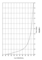
- the bottom hole temperature is very high, and may exceed 400 degrees Celsius. Following the start-up phase, the bottom hole temperature decreases over time to a steady state temperature, for example 150 degrees Celsius. This is illustrated in Figure 1 .
- the working fluid experiences very little temperature drop as it travels up. Therefore, a large temperature differential can result between the inner diameter and outer diameter of the insulated tubing string which can cause mechanical stress and in some cases failure of the insulated tubing string.
- an aspect of the invention provides a tubing apparatus for use in a geothermal well, the apparatus comprising an insulated tubing string describing a conduit configured to convey a working fluid between a surface location and a subsurface location, and a cooling string configured to adjust, in use, the temperature of the working fluid within or around the conduit and/or as it is conveyed toward the surface location.
- a cooling string that adjusts the temperature of the working fluid enables the temperature differential between the fluid conveyed toward the surface location within or around the conduit, typically within the insulated tubing string or within an annular space surrounding the insulated tubing string, and the fluid respectively around or within the conduit to be reduced during start-up.
- the tubing apparatus may further comprise a casing string.
- the insulated tubing string may be located within the casing string, e.g. such that an annular space is described therebetween.
- Another aspect of the invention provides a geothermal well comprising a wellbore within which is received an insulated tubing string describing a conduit configured to convey a working fluid between a surface location and a subsurface location, and a cooling string configured to adjust, in use, the temperature of the working fluid as it is conveyed toward the surface location.
- the tubing apparatus or the geothermal well may be operable or configured to convey, in use, the working fluid from the subsurface location to the surface location, e.g. through the insulated tubing string.
- the tubing apparatus may be operable or configured to convey, in use, the working fluid from the surface location to the subsurface location, e.g. through an annular space between the insulated tubing string and the casing string or the wellbore.
- geothermal well comprising an insulated tubing string located within a wellbore, wherein the geothermal well is operable or configured to convey, in use, a working fluid from a subsurface location to a surface location through the insulated tubing string and to convey the working fluid from the surface location to the subsurface location through an annular space between the insulated tubing string and the wellbore.
- the inventor has also observed that, with a conventional flow, the temperature of the working fluid is reduced as it is conveyed up the annular space, via conduction through the wellbore casing. By reversing the direction of flow, the working fluid is heated as it is pumped down the wellbore, by virtue of its exposure to the surrounding formation, whilst heat is retained in the fluid as it is conveyed back up the insulated tubing string.
- the cooling string may be received within the insulated tubing string.
- the cooling string may be removably received within the insulated tubing string, e.g. to enable it to be removed after start-up. This configuration is useful when the working fluid is conveyed up the insulated tubing string, since the temperature differential can be more acute with such a reverse flow configuration.
- the cooling string may be external of the insulated tubing string and/or between the insulated tubing string and the casing string.
- the cooling string may be removably received between the insulated tubing string and the casing string, e.g. to enable it to be removed after start-up. This configuration is useful when the working fluid is conveyed up the annular space.
- the insulated tubing string may comprise a pipe-in-pipe insulated tubing string.
- the pipe-in-pipe insulated tubing string may comprise a vacuum or an inert gas between the pipes making up the pipe-in-pipe insulated tubing string.
- the insulated tubing string or pipe-in-pipe insulated tubing string may comprise a vacuum insulated tubing string.
- the insulated tubing string or pipe-in-pipe insulated tubing string may comprise an inert gas, e.g. argon, insulated tubing string.
- the insulated tubing string may be arranged substantially concentrically with the casing string and/or with the wellbore.
- the insulated tubing string may be longer than the casing string and/or may extend, in use, beyond the casing string, e.g. into the or a wellbore and/or to a bottom hole location.
- the cooling string may be configured to inject or convey, in use, a fluid, e.g. a cooling fluid, into the conduit, e.g. so as to adjust the temperature of the working fluid.
- the cooling fluid may be configured to reduce the temperature of the working fluid.
- a bottom end of the cooling string is preferably open or free.
- the cooling fluid may comprise a cooled portion of the working fluid.
- the tubing apparatus may comprise a bypass circuit or cooling circuit or bypass cooling circuit, which may be configured to cool a portion of the working fluid.
- the cooling string may be supplied by the bypass circuit or cooling circuit or bypass cooling circuit.
- a bottom end of the cooling string may be closed, in which case the cooling string may comprise one or more holes or perforations on a sidewall thereof or it may comprise a cooling circuit formed by a pair of concentric tubes.
- the cooling string may have a smaller flow area than the insulated tubing string and/or than the annular space.
- the cooling string may have a smaller diameter than the.insulated tubing string and/or than the radial width of the annular space. This minimises the impact of the cooling string on the flow of working fluid, and reflects the intention for a lower flow rate of the cooling fluid as compared with the working fluid.
- the insulated tubing string may have a substantially circular cross-sectional shape.
- the cooling string may have a substantially circular cross-sectional shape.
- the insulated tubing string and/or the cooling string may have a non-round shape, for example a substantially elliptical cross-sectional shape.
- the cross-sectional shape of the insulated tubing string may be the same, similar or different to that of the cooling string. The shape may be optimised to minimise the impact on the flow of working fluid.
- the cooling string may be located or positioned adjacent an inner wall of the insulated tubing string.
- the cooling string may be located concentrically with the insulated cooling string. This position also reduces the impact on the flow of working fluid.
- the cooling string may be held in place, e.g. relative to the insulated tubing string, by one or more brackets or supports.
- the apparatus may comprise one or more brackets or supports configured to mount or support the cooling string relative to the insulated tubing string.
- the cooling string may be mounted or held in place by a plurality of brackets or supports spaced along the cooling string and/or spaced along the insulated tubing string.
- brackets or supports may be connected, attached or fixed to the insulated tubing string.
- brackets or supports may be connected, attached or fixed to the cooling string.
- the cooling string may be shorter than the insulated tubing string.
- a bottom end or free end of the cooling string may be arranged to be located short of the bottom end or free end of the insulated tubing string.
- the cooling string may be removable from the insulated tubing string.
- the cooling string may be provided on a coiled tubing arrangement. The cooling string can therefore be removed after the start-up phase.
- the cooling string may be permanently installed within the insulated tubing string.
- the bottom end of the insulated tubing string may be open and/or arranged to be located in an open-hole portion of a wellbore.
- An open-hole portion may be an un-cased portion of a wellbore.
- the tubing apparatus may comprise a controller.
- the controller may be configured to control the flow rate and/or pressure of the working fluid.
- the controller may be configured to control the flow rate and/or pressure of cooling fluid. This enables the temperature of the working fluid to be adjusted both incrementally and dynamically.
- the controller may be configured to control the flow rate and/or pressure of the working fluid.
- the controller may be configured to control the flow rate and/or pressure of cooling fluid.
- the well head control assembly may comprise a controller, which may be configured to control the flow rate and/or pressure of a working fluid and/or the flow rate and/or pressure of cooling fluid through a tubing apparatus of a geothermal well.
- the tubing apparatus may comprise a tubing apparatus as described above.
- the tubing apparatus or control assembly may comprise one or more flow sensors.
- One or more flow sensors may be configured to measure, in use, the flow rate through the annular space, insulated tubing string and/or cooling string.
- the one or more flow sensors may include a first flow sensor configured to measure, in use, the flow rate through the annular space.
- the one or more flow sensors may include a second flow sensor configured to measure, in use, the flow rate through the cooling string.
- the one or more flow sensors may include a third flow sensor configured to measure, in use, the flow rate through the insulated tubing string. This enables closed loop feedback of the relative flow rates of the working fluid and cooling fluid.
- the tubing apparatus or control assembly may comprise one or more pressure sensors.
- One or more pressure sensors may be configured to measure, in use, the pressure in the annular space, insulated tubing string and/or cooling string.
- the one or more pressure sensors may include a first pressure sensor configured to measure, in use, the pressure in the annular space.
- the one or more pressure sensors may include a second pressure sensor configured to measure, in use, the pressure in the cooling string.
- the one or more pressure sensors may include a third pressure sensor configured to measure, in use, the pressure in the insulated tubing string. This enables closed loop feedback of the relative pressures of the working fluid and cooling fluid.
- the tubing apparatus or control assembly may comprise one or more flow control valves.
- One or more flow control valves may be configured to control the flow of fluid through the annular space and/or insulated tubing string.
- One or more flow control valves may be configured to control the flow of fluid through the cooling string.
- the one or more flow control valves may comprise one or more first flow control valves for controlling the flow of fluid through the annular space and/or insulated tubing string.
- the one or more flow control valves may comprise a second flow control valve for controlling the flow of fluid through the cooling string. This enables the relative flow rates of the working fluid and cooling fluid to be adjusted incrementally and dynamically.
- the tubing apparatus or control assembly may comprise one or more temperature sensors.
- One or more temperature sensors may be located at or proximate a surface location in the insulated tubing string.
- One or more temperature sensors may be configured to measure the temperature of the working fluid within the insulated tubing string.
- One or more temperature sensors may be located at or proximate the bottom end or free end of the cooling string. This enables a closed loop adjustment of the relative flow rates of the working fluid and cooling fluid to achieve the requisite temperature(s) in the working fluid.
- the geothermal well may comprise a tubing apparatus as described above.
- the geothermal well may comprise a controller as described above.
- the geothermal well may comprise a control assembly as described above.
- the geothermal well is a closed-loop geothermal well.
- Another aspect of the invention provides a method of operating or starting up a geothermal well, the method comprising: circulating a working fluid between a surface location and a subsurface location via an insulated tubing string; and adjusting the temperature of the working fluid as it is circulated toward the surface using a cooling string.
- the method may comprise conveying a working fluid from a surface location to a subsurface location, e.g. through an insulated tubing string.
- the method may comprise conveying the working fluid from the subsurface location to the surface location, e.g. through an annular space between the insulated tubing string and a casing string or wellbore.
- the method may comprise conveying a working fluid from a subsurface location to a surface location, e.g. through an insulated tubing string.
- the method may comprise conveying the working fluid from the surface location to the subsurface location, e.g. through an annular space between the insulated tubing string and a casing string or wellbore.
- Another aspect of the invention provides a method of operating a geothermal well comprising: conveying a working fluid from a subsurface location to a surface location through an insulated tubing string; and conveying the working fluid from the surface location to the subsurface location through an annular space between the insulated tubing string and a casing string or wellbore.
- the method may comprise injecting a cooling fluid through the cooling string and/or into the working fluid, e.g. so as to adjust the temperature of the working fluid as it is circulated toward the surface.
- the cooling fluid may be injected so as to reduce the temperature of the working fluid.
- the flow rate of working fluid circulated between the surface location and the bottom hole and/or the flow rate of cooling fluid injected into the working fluid may be controlled, e.g. in order to manage the temperature of the working fluid received back at the surface.
- Injecting the cooling fluid through the cooling string may comprise injecting working fluid.
- the method may comprise cooling a portion of the working fluid, e.g. before injecting it through the cooling string.
- the method may comprise bypassing a portion of the working fluid, e.g. through a bypass circuit or cooling circuit or bypass cooling circuit, before injecting it through the cooling string.
- the working fluid may comprise water or another fluid, e.g. a supercritical fluid.
- the method may comprise removing the cooling string once the temperature of the working fluid received at the surface is below a predetermined threshold.
- the tubing apparatus may comprise any one or more features of the method relevant to the tubing apparatus and/or the method may comprise any one or more features or steps relevant to one or more features of the tubing apparatus or the cooling string.
- a further aspect of the invention provides a computer program element comprising computer readable program code means for causing a processor to execute a procedure to implement one or more steps of the aforementioned method.
- a yet further aspect of the invention provides the computer program element embodied on a computer readable medium.
- a yet further aspect of the invention provides a computer readable medium having a program stored thereon, where the program is arranged to make a computer execute a procedure to implement one or more steps of the aforementioned method.
- a yet further aspect of the invention provides a control means or control system or controller comprising the aforementioned computer program element or computer readable medium.
- any controller(s), control units and/or control modules described herein may each comprise a control unit or computational device having one or more electronic processors.
- the controller may comprise a single control unit or electronic controller or alternatively different functions of the control of the system or apparatus may be embodied in, or hosted in, different control units or controllers or control modules.
- control unit and “controller” will be understood to include both a single control unit or controller and a plurality of control units or controllers collectively operating to provide the required control functionality.
- a set of instructions could be provided which, when executed, cause said controller(s) or control unit(s) or control module(s) to implement the control techniques described herein (including the method(s) described herein).
- the set of instructions may be embedded in one or more electronic processors, or alternatively, may be provided as software to be executed by one or more electronic processor(s).
- a first controller may be implemented in software run on one or more electronic processors, and one or more other controllers may also be implemented in software run on or more electronic processors, optionally the same one or more processors as the first controller. It will be appreciated, however, that other arrangements are also useful, and therefore, the present invention is not intended to be limited to any particular arrangement.
- the set of instructions described herein may be embedded in a computer-readable storage medium (e.g., a non-transitory storage medium) that may comprise any mechanism for storing information in a form readable by a machine or electronic processors/computational device, including, without limitation: a magnetic storage medium (e.g., floppy diskette); optical storage medium (e.g., CD-ROM); magneto optical storage medium; read only memory (ROM); random access memory (RAM); erasable programmable memory (e.g., EPROM ad EEPROM); flash memory; or electrical or other types of medium for storing such information/instructions.
- a computer-readable storage medium e.g., a non-transitory storage medium
- a magnetic storage medium e.g., floppy diskette
- optical storage medium e.g., CD-ROM
- magneto optical storage medium e.g., magneto optical storage medium
- ROM read only memory
- RAM random access memory
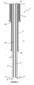
- the tubing apparatus 1 for a geothermal well according to the prior art.
- the tubing apparatus 1 includes a vacuum insulated tubing string 2 received within an intermediate casing string 3, which is, in turn, received within a surface casing string 4.
- the vacuum insulated tubing string 2 and casing strings 3, 4 describe a wellbore.
- Each of the vacuum insulated tubing string 2, intermediate casing string 3 and surface casing string 4 extend from a surface location A into a formation F, which is in the form of a hot sedimentary aquifer in this example.
- the intermediate casing string 3 includes a casing shoe 30 at its lower end.
- the casing string 4 also includes a casing shoe 40 at its lower end.
- the vacuum insulated tubing string 2 has a first open end 20 connected to a source of working fluid located at the surface location A and a second open end 21 located within an open-hole (un-cased) portion of the wellbore 5.
- the second, open end 21 of the vacuum insulated tubing string 2 is located deeper than the respective casing shoes 30, 40 of the intermediate casing string 3 and surface casing string 4.
- the vacuum insulated tubing string 2 describes an insulated conduit 22 extending between the surface location A and the formation F.
- annular space 6 is described between the vacuum insulated tubing string 2 and the intermediate casing string 3, or open-hole portion, of the wellbore 5.
- the annular space 6 extends between the surface location A and a bottom-hole location B.
- a working fluid is pumped down the conduit 22 from the surface location A.
- the fluid exits the vacuum insulated tubing string 2 at the second, open end 21 where it is exposed to the formation F..
- the working fluid then passes along the annular space 6 back toward the surface location A. As the working fluid passes along the annular space 6 it is heated due to the heat of the surrounding formation F. The heat is then extracted from the working fluid when it reaches the surface location A.
- the circulation may be reversed. This involves pumping fluid down the annular space 6 between the vacuum insulated tubing string 2 and the intermediate casing string 3. The working fluid is then conveyed up through the conduit 22 from the bottom-hole location B to the surface location A.
- the working fluid is heated as it is pumped down the wellbore by virtue of its exposure to the surrounding formation, whilst heat is retained in the fluid as it is conveyed back up the insulated tubing string.
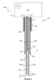
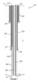
- tubing apparatus 101 for a geothermal well which incorporates another aspect of the invention.
- the tubing apparatus 101 is similar to tubing apparatus 1 and like features are denoted by like references incremented by '100', which will not be described further herein.
- the tubing apparatus 101 differs from the tubing apparatus 1 of Figure 2 in that there is provided a cooling string 107, such cooling string being arranged within the vacuum insulated tubing string 102 in the embodiment shown in Figure 3 .
- the cooling string 107 is located adjacent a sidewall of the vacuum insulated tubing string 102, thereby to minimise its impact on the flow of working fluid through the vacuum insulated tubing string 102.
- the cooling string 107 has a first open end 170 connected to a source of cooling fluid located at the surface location A and a second, open end 171 located within the conduit 122 and short of the second, open end 121 of the vacuum insulated tubing string 102.
- the cooling string 107 is configured to inject a cooling fluid, e.g. water or working fluid passed through a bypass cooling circuit, into the conduit 122 in order to adjust the temperature of the working fluid within the conduit 122.
- a cooling fluid e.g. water or working fluid passed through a bypass cooling circuit
- the geothermal well 100 also includes a well head control assembly 110, which includes a controller 111, a first flow sensor 112 configured to measure the flow rate through the annular space 106, a second flow sensor 113 configured to measure the flow rate through the cooling string 107 and a third flow sensor 114 configured to measure the flow rate through the vacuum insulated tubing string 102.
- a well head control assembly 110 which includes a controller 111, a first flow sensor 112 configured to measure the flow rate through the annular space 106, a second flow sensor 113 configured to measure the flow rate through the cooling string 107 and a third flow sensor 114 configured to measure the flow rate through the vacuum insulated tubing string 102.
- the head control assembly 110 also includes a temperature sensor 115 and flow control valves (not shown)
- the temperature sensor 115 is at a surface location in the vacuum insulated tubing string 102 and proximate the open end 171 of the cooling string 107, which is configured to measure the temperature of the working fluid.
- the flow control valves (not shown) are configured to control the flow of fluid through the annular space 106, through the vacuum insulated tubing string 102 and trough the cooling string 107.
- Each of the flow sensors 112, 113, 114, the temperature sensor 115 and the flow control valves (not shown) is operatively connected to the controller 111. This may be via a wired or wireless connection.
- the geothermal well 100 works in essentially the same manner as described above in relation to a geothermal well with the tubing apparatus 1 of Figure 2 .
- the cooling string 107 has a particular purpose in the context of the operation of the geothermal well 100, particularly during the start-up phase.
- a working fluid is circulated down the annular space 106 and back up the conduit 122 to the surface location A.
- the working fluid enters the vacuum insulated tubing string 102 at the second, open end 121.
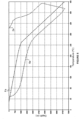
- Figure 5 illustrates the temperature of the working fluid within the tubing apparatus 1 during a start-up phase.
- the temperature of the formation F along the depth of the wellbore is illustrated by a first line Fa.
- the temperature of the working fluid flowing down the annular space 6 is illustrated by a second line 6a.
- the temperature of the working fluid flowing up the vacuum insulated tubing string 2 is illustrated by a third line 2a. It is clear from this graph that, at the surface, there is a temperature difference of over 240°C between the fluid temperature in the vacuum insulated tubing string 2, compared with the fluid temperature within the annular space 6 surrounding the vacuum insulated tubing string 2.
- the fluid entering the vacuum insulated tubing string 2 at the second open end 21 is at, or close to, the bottom hole temperature. Due to the insulative properties of the vacuum insulated tubing string 2, there is very little temperature reduction in the working fluid as it makes its way toward the surface location A.
- Figure 6 illustrates the temperature of the working fluid within the tubing apparatus 1 during steady-state. Similar to the graph of Figure 5 , a first line Fb represents the temperature of the formation F along the depth of the wellbore, a second line 6b represents the temperature of the working fluid flowing down the annular space 6 and a third line 2b represents the temperature of the working fluid flowing up the vacuum insulated tubing string 2. In this, steady-state the temperature difference at the surface is approximately 40°C.
- the vacuum insulated tubing string 2 therefore must be designed to withstand a very high temperature difference only during the start-up phase, or that start-up phase must be carried out very slowly. The skilled person will appreciate that both of these have substantial cost implications.
- a cooling fluid is injected through the cooling string 107 and into the working fluid as it passes along the conduit 122, thereby reducing its temperature.
- the resulting working fluid has a lower temperature as it reaches the surface location A.
- This provides a temperature differential between the working fluid within the vacuum insulated tubing string 102 and the working fluid surrounding it, within the annular space 106.
- the cooling fluid is injected to maintain, during the start-up phase, a predetermined temperature difference between the working fluid within the vacuum insulated tubing string 102 and in the annular space 106 surrounding it.
- the invention reduces the mechanical stress exerted on the vacuum insulated tubing string 102. This is achieved by virtue of the introduction of cooling fluid from the cooling string 107 in the region where the working fluid would otherwise be at or near its highest temperature.
- the invention thereby avoids the need for larger, heavier and more expensive vacuum insulated tubing string, and without the need to slow the start-up phase.
- the cooling fluid is for instance some working fluid available near the surface location A, such a working fluid available near the surface location A having a low temperature compared to the working fluid traveling up to the surface location A which have been heated while passing through the bottom of the geothermal well.
- FIG. 7 there is shown a tubing apparatus 201 according to another example, which is similar to tubing apparatus 101 of Figure 3 , wherein like features are denoted by like references incremented by '100', which will not be described further herein.
- the tubing apparatus 201 differs from the tubing apparatus 101 of Figure 3 in that the cooling string 207 is within the annular space 206 between the vacuum insulated tubing string 202 and the intermediate casing string 203, or open-hole portion, of the wellbore 205.
- the cooling string 207 is located adjacent the casing string 203, thereby to minimise its impact on the flow of working fluid through the annular space 206.
- This tubing apparatus 201 is configured to pump the working fluid down the conduit 222 from the surface location A, which is then exposed to the formation F, and is conveyed back up the annular space 206 toward the surface location A.
- the cooling fluid is injected into the working fluid via the cooling string 207 and as it passes along the annular space 206, thereby reducing its temperature.
- the working fluid has a lower temperature as it reaches the surface location A, by virtue of the cooling fluid introduced by the cooling string 207. This reduces the temperature differential between the working fluid within the vacuum insulated tubing string 202 and the working fluid surrounding it, within the annular space 206.
Landscapes
- Engineering & Computer Science (AREA)
- Life Sciences & Earth Sciences (AREA)
- Hydrology & Water Resources (AREA)
- Sustainable Development (AREA)
- Sustainable Energy (AREA)
- Chemical & Material Sciences (AREA)
- Combustion & Propulsion (AREA)
- Mechanical Engineering (AREA)
- General Engineering & Computer Science (AREA)
- Earth Drilling (AREA)
- Rigid Pipes And Flexible Pipes (AREA)
Priority Applications (4)
| Application Number | Priority Date | Filing Date | Title |
|---|---|---|---|
| EP22315084.8A EP4261473A1 (fr) | 2022-04-12 | 2022-04-12 | Puits géothermique, et appareil de tubage correspondant |
| JP2024556070A JP2025510717A (ja) | 2022-04-12 | 2023-04-06 | 地熱井、およびそのためのチュービング装置 |
| US18/847,865 US20250207822A1 (en) | 2022-04-12 | 2023-04-06 | Geothermal well and tubing apparatus therefor |
| PCT/IB2023/053532 WO2023199183A1 (fr) | 2022-04-12 | 2023-04-06 | Puits géothermique et appareil de tubage associé |
Applications Claiming Priority (1)
| Application Number | Priority Date | Filing Date | Title |
|---|---|---|---|
| EP22315084.8A EP4261473A1 (fr) | 2022-04-12 | 2022-04-12 | Puits géothermique, et appareil de tubage correspondant |
Publications (1)
| Publication Number | Publication Date |
|---|---|
| EP4261473A1 true EP4261473A1 (fr) | 2023-10-18 |
Family
ID=81579997
Family Applications (1)
| Application Number | Title | Priority Date | Filing Date |
|---|---|---|---|
| EP22315084.8A Pending EP4261473A1 (fr) | 2022-04-12 | 2022-04-12 | Puits géothermique, et appareil de tubage correspondant |
Country Status (4)
| Country | Link |
|---|---|
| US (1) | US20250207822A1 (fr) |
| EP (1) | EP4261473A1 (fr) |
| JP (1) | JP2025510717A (fr) |
| WO (1) | WO2023199183A1 (fr) |
Citations (5)
| Publication number | Priority date | Publication date | Assignee | Title |
|---|---|---|---|---|
| US4030549A (en) * | 1976-01-26 | 1977-06-21 | Cities Service Company | Recovery of geothermal energy |
| WO1985003994A1 (fr) * | 1984-03-02 | 1985-09-12 | Geo-Thermal Müszaki Fejlesztési És Hasznositási Ki | Procede et puits profond pour l'extraction de l'energie geothermique |
| US20080073058A1 (en) * | 2006-09-22 | 2008-03-27 | Hiroaki Ueyama | Double-Pipe geothermal water circulating apparatus |
| US20150122453A1 (en) * | 2013-11-06 | 2015-05-07 | Controlled Thermal Technologies Pty Ltd | Geothermal loop in-ground heat exchanger for energy extraction |
| GB2549832A (en) * | 2016-03-08 | 2017-11-01 | Henderson William | Geothermal power system |
Family Cites Families (14)
| Publication number | Priority date | Publication date | Assignee | Title |
|---|---|---|---|---|
| US3160208A (en) * | 1961-10-06 | 1964-12-08 | Shell Oil Co | Production well assembly for in situ combustion |
| US4705113A (en) * | 1982-09-28 | 1987-11-10 | Atlantic Richfield Company | Method of cold water enhanced hydraulic fracturing |
| JPS60134161A (ja) * | 1983-12-22 | 1985-07-17 | Ebara Corp | 熱水井戸制御装置 |
| AT404386B (de) * | 1994-05-25 | 1998-11-25 | Johann Dipl Ing Springer | Doppelwandiger thermisch isolierter tubingstrang |
| JP3101183B2 (ja) * | 1995-07-28 | 2000-10-23 | 株式会社新潟鉄工所 | 温泉水の揚水装置及び揚水方法 |
| JPH11210368A (ja) * | 1998-01-20 | 1999-08-03 | Nichijuu Kensetsu Kk | 温泉揚湯方法およびその装置 |
| US9874077B2 (en) * | 2008-04-30 | 2018-01-23 | Altarock Energy Inc. | Method and cooling system for electric submersible pumps/motors for use in geothermal wells |
| US20110220317A1 (en) * | 2010-03-11 | 2011-09-15 | Kelix Heat Transfer Systems, Llc | Apparatus and process for controlling the flow rate of heat transferring fluid flowing through a ground loop heat exchanging (glhe) subsystem constructed from one or more ground heat exchangers (ghe) while operably connected to geothermal equipment (gte) including a refrigerant compressor and associated with a geothermal system |
| US9194214B2 (en) * | 2012-01-31 | 2015-11-24 | World Energy Systems Incorporated | Method and system for controlling wellbore production temperature |
| KR101605304B1 (ko) * | 2014-03-27 | 2016-03-22 | 주식회사 지앤지테크놀러지 | 물넘침 방지 기능을 갖는 개방형 게오일 지열 지중 열교환 장치 및 이를 이용한 지하수 유량 제어 방법 |
| GB2565098B (en) * | 2017-08-01 | 2020-07-22 | Deltatek Oil Tools Ltd | Work string for a borehole |
| JP7218147B2 (ja) * | 2018-10-24 | 2023-02-06 | 耕二 盛田 | 地中熱交換器を用いた地熱発電システム |
| EP3959418B1 (fr) * | 2019-04-26 | 2024-03-27 | General Energy Recovery Inc. | Appareil, procédé et installation de puits de forage pour atténuer l'endommagement thermique d'éléments de puits pendant une injection de fluide à haute température |
| CN116368335A (zh) * | 2020-08-05 | 2023-06-30 | 埃沃尔技术股份有限公司 | 使用多种工作流体来生成地热能 |
-
2022
- 2022-04-12 EP EP22315084.8A patent/EP4261473A1/fr active Pending
-
2023
- 2023-04-06 JP JP2024556070A patent/JP2025510717A/ja active Pending
- 2023-04-06 WO PCT/IB2023/053532 patent/WO2023199183A1/fr not_active Ceased
- 2023-04-06 US US18/847,865 patent/US20250207822A1/en active Pending
Patent Citations (5)
| Publication number | Priority date | Publication date | Assignee | Title |
|---|---|---|---|---|
| US4030549A (en) * | 1976-01-26 | 1977-06-21 | Cities Service Company | Recovery of geothermal energy |
| WO1985003994A1 (fr) * | 1984-03-02 | 1985-09-12 | Geo-Thermal Müszaki Fejlesztési És Hasznositási Ki | Procede et puits profond pour l'extraction de l'energie geothermique |
| US20080073058A1 (en) * | 2006-09-22 | 2008-03-27 | Hiroaki Ueyama | Double-Pipe geothermal water circulating apparatus |
| US20150122453A1 (en) * | 2013-11-06 | 2015-05-07 | Controlled Thermal Technologies Pty Ltd | Geothermal loop in-ground heat exchanger for energy extraction |
| GB2549832A (en) * | 2016-03-08 | 2017-11-01 | Henderson William | Geothermal power system |
Also Published As
| Publication number | Publication date |
|---|---|
| US20250207822A1 (en) | 2025-06-26 |
| JP2025510717A (ja) | 2025-04-15 |
| WO2023199183A1 (fr) | 2023-10-19 |
Similar Documents
| Publication | Publication Date | Title |
|---|---|---|
| US8037936B2 (en) | Method of heating sub sea ESP pumping system | |
| US12000384B2 (en) | Flow control for geothermal well | |
| RU2421605C1 (ru) | Способ эксплуатации скважины, оборудованной установкой электроцентробежного насоса с частотно-регулируемым приводом | |
| US10539128B2 (en) | Horizontal and vertical well fluid pumping system | |
| US9702233B2 (en) | In situ hydrocarbon recovery using distributed flow control devices for enhancing temperature conformance | |
| NO20111176A1 (no) | Elektrisk neddykkbar pumpe, ror, og fremgangsmate for borehullproduksjon | |
| EA003012B1 (ru) | Система для увеличения потока текучей среды в буровой скважине | |
| US11226137B2 (en) | Flow control in geothermal wells | |
| AU2019232819B2 (en) | Lubricating downhole-type rotating machines | |
| GB2457788A (en) | System and method for removing liquid from a gas well | |
| EP4261473A1 (fr) | Puits géothermique, et appareil de tubage correspondant | |
| US12291950B2 (en) | Downhole lubrication system | |
| CA2882507A1 (fr) | Commande de sous-refroidissement automatisee | |
| US9382785B2 (en) | Shaped memory devices and method for using same in wellbores | |
| US10837268B2 (en) | Methods and apparatus for producing fluids from a well | |
| CA2953430C (fr) | Perfectionnements apportes a la production de fluides a partir de reservoirs | |
| US20250207820A1 (en) | Groundwater heat exchange system | |
| WO2020146234A1 (fr) | Élimination de liquide par un système de compression sous la surface | |
| RU2725415C1 (ru) | Способ разработки залежи высоковязкой нефти с использованием парных горизонтальных скважин | |
| CA3170628C (fr) | Contrôle du débit dans les puits géothermiques | |
| CA2953434C (fr) | Ameliorations apportees au transport de fluides a partir de puits | |
| CA2650199C (fr) | Methode de chauffage des systemes de pompage electrique submersible profond |
Legal Events
| Date | Code | Title | Description |
|---|---|---|---|
| PUAI | Public reference made under article 153(3) epc to a published international application that has entered the european phase |
Free format text: ORIGINAL CODE: 0009012 |
|
| STAA | Information on the status of an ep patent application or granted ep patent |
Free format text: STATUS: THE APPLICATION HAS BEEN PUBLISHED |
|
| AK | Designated contracting states |
Kind code of ref document: A1 Designated state(s): AL AT BE BG CH CY CZ DE DK EE ES FI FR GB GR HR HU IE IS IT LI LT LU LV MC MK MT NL NO PL PT RO RS SE SI SK SM TR |
|
| STAA | Information on the status of an ep patent application or granted ep patent |
Free format text: STATUS: REQUEST FOR EXAMINATION WAS MADE |
|
| 17P | Request for examination filed |
Effective date: 20240229 |
|
| RBV | Designated contracting states (corrected) |
Designated state(s): AL AT BE BG CH CY CZ DE DK EE ES FI FR GB GR HR HU IE IS IT LI LT LU LV MC MK MT NL NO PL PT RO RS SE SI SK SM TR |
|
| STAA | Information on the status of an ep patent application or granted ep patent |
Free format text: STATUS: EXAMINATION IS IN PROGRESS |
|
| 17Q | First examination report despatched |
Effective date: 20241030 |