EP4261475A1 - Dispositif à cycle de réfrigération - Google Patents
Dispositif à cycle de réfrigération Download PDFInfo
- Publication number
- EP4261475A1 EP4261475A1 EP20965118.1A EP20965118A EP4261475A1 EP 4261475 A1 EP4261475 A1 EP 4261475A1 EP 20965118 A EP20965118 A EP 20965118A EP 4261475 A1 EP4261475 A1 EP 4261475A1
- Authority
- EP
- European Patent Office
- Prior art keywords
- refrigerant
- pipe
- control device
- gas
- refrigeration cycle
- Prior art date
- Legal status (The legal status is an assumption and is not a legal conclusion. Google has not performed a legal analysis and makes no representation as to the accuracy of the status listed.)
- Pending
Links
Images


Classifications
-
- F—MECHANICAL ENGINEERING; LIGHTING; HEATING; WEAPONS; BLASTING
- F25—REFRIGERATION OR COOLING; COMBINED HEATING AND REFRIGERATION SYSTEMS; HEAT PUMP SYSTEMS; MANUFACTURE OR STORAGE OF ICE; LIQUEFACTION SOLIDIFICATION OF GASES
- F25B—REFRIGERATION MACHINES, PLANTS OR SYSTEMS; COMBINED HEATING AND REFRIGERATION SYSTEMS; HEAT PUMP SYSTEMS
- F25B41/00—Fluid-circulation arrangements
- F25B41/30—Expansion means; Dispositions thereof
- F25B41/39—Dispositions with two or more expansion means arranged in series, i.e. multi-stage expansion, on a refrigerant line leading to the same evaporator
-
- F—MECHANICAL ENGINEERING; LIGHTING; HEATING; WEAPONS; BLASTING
- F25—REFRIGERATION OR COOLING; COMBINED HEATING AND REFRIGERATION SYSTEMS; HEAT PUMP SYSTEMS; MANUFACTURE OR STORAGE OF ICE; LIQUEFACTION SOLIDIFICATION OF GASES
- F25B—REFRIGERATION MACHINES, PLANTS OR SYSTEMS; COMBINED HEATING AND REFRIGERATION SYSTEMS; HEAT PUMP SYSTEMS
- F25B31/00—Compressor arrangements
- F25B31/006—Cooling of compressor or motor
- F25B31/008—Cooling of compressor or motor by injecting a liquid
-
- F—MECHANICAL ENGINEERING; LIGHTING; HEATING; WEAPONS; BLASTING
- F25—REFRIGERATION OR COOLING; COMBINED HEATING AND REFRIGERATION SYSTEMS; HEAT PUMP SYSTEMS; MANUFACTURE OR STORAGE OF ICE; LIQUEFACTION SOLIDIFICATION OF GASES
- F25B—REFRIGERATION MACHINES, PLANTS OR SYSTEMS; COMBINED HEATING AND REFRIGERATION SYSTEMS; HEAT PUMP SYSTEMS
- F25B41/00—Fluid-circulation arrangements
-
- F—MECHANICAL ENGINEERING; LIGHTING; HEATING; WEAPONS; BLASTING
- F25—REFRIGERATION OR COOLING; COMBINED HEATING AND REFRIGERATION SYSTEMS; HEAT PUMP SYSTEMS; MANUFACTURE OR STORAGE OF ICE; LIQUEFACTION SOLIDIFICATION OF GASES
- F25B—REFRIGERATION MACHINES, PLANTS OR SYSTEMS; COMBINED HEATING AND REFRIGERATION SYSTEMS; HEAT PUMP SYSTEMS
- F25B49/00—Arrangement or mounting of control or safety devices
- F25B49/02—Arrangement or mounting of control or safety devices for compression type machines, plants or systems
-
- F—MECHANICAL ENGINEERING; LIGHTING; HEATING; WEAPONS; BLASTING
- F25—REFRIGERATION OR COOLING; COMBINED HEATING AND REFRIGERATION SYSTEMS; HEAT PUMP SYSTEMS; MANUFACTURE OR STORAGE OF ICE; LIQUEFACTION SOLIDIFICATION OF GASES
- F25B—REFRIGERATION MACHINES, PLANTS OR SYSTEMS; COMBINED HEATING AND REFRIGERATION SYSTEMS; HEAT PUMP SYSTEMS
- F25B2400/00—General features or devices for refrigeration machines, plants or systems, combined heating and refrigeration systems or heat-pump systems, i.e. not limited to a particular subgroup of F25B
- F25B2400/13—Economisers
-
- F—MECHANICAL ENGINEERING; LIGHTING; HEATING; WEAPONS; BLASTING
- F25—REFRIGERATION OR COOLING; COMBINED HEATING AND REFRIGERATION SYSTEMS; HEAT PUMP SYSTEMS; MANUFACTURE OR STORAGE OF ICE; LIQUEFACTION SOLIDIFICATION OF GASES
- F25B—REFRIGERATION MACHINES, PLANTS OR SYSTEMS; COMBINED HEATING AND REFRIGERATION SYSTEMS; HEAT PUMP SYSTEMS
- F25B2400/00—General features or devices for refrigeration machines, plants or systems, combined heating and refrigeration systems or heat-pump systems, i.e. not limited to a particular subgroup of F25B
- F25B2400/23—Separators
-
- F—MECHANICAL ENGINEERING; LIGHTING; HEATING; WEAPONS; BLASTING
- F25—REFRIGERATION OR COOLING; COMBINED HEATING AND REFRIGERATION SYSTEMS; HEAT PUMP SYSTEMS; MANUFACTURE OR STORAGE OF ICE; LIQUEFACTION SOLIDIFICATION OF GASES
- F25B—REFRIGERATION MACHINES, PLANTS OR SYSTEMS; COMBINED HEATING AND REFRIGERATION SYSTEMS; HEAT PUMP SYSTEMS
- F25B2600/00—Control issues
- F25B2600/05—Refrigerant levels
-
- F—MECHANICAL ENGINEERING; LIGHTING; HEATING; WEAPONS; BLASTING
- F25—REFRIGERATION OR COOLING; COMBINED HEATING AND REFRIGERATION SYSTEMS; HEAT PUMP SYSTEMS; MANUFACTURE OR STORAGE OF ICE; LIQUEFACTION SOLIDIFICATION OF GASES
- F25B—REFRIGERATION MACHINES, PLANTS OR SYSTEMS; COMBINED HEATING AND REFRIGERATION SYSTEMS; HEAT PUMP SYSTEMS
- F25B2600/00—Control issues
- F25B2600/25—Control of valves
- F25B2600/2509—Economiser valves
-
- F—MECHANICAL ENGINEERING; LIGHTING; HEATING; WEAPONS; BLASTING
- F25—REFRIGERATION OR COOLING; COMBINED HEATING AND REFRIGERATION SYSTEMS; HEAT PUMP SYSTEMS; MANUFACTURE OR STORAGE OF ICE; LIQUEFACTION SOLIDIFICATION OF GASES
- F25B—REFRIGERATION MACHINES, PLANTS OR SYSTEMS; COMBINED HEATING AND REFRIGERATION SYSTEMS; HEAT PUMP SYSTEMS
- F25B2600/00—Control issues
- F25B2600/25—Control of valves
- F25B2600/2513—Expansion valves
-
- F—MECHANICAL ENGINEERING; LIGHTING; HEATING; WEAPONS; BLASTING
- F25—REFRIGERATION OR COOLING; COMBINED HEATING AND REFRIGERATION SYSTEMS; HEAT PUMP SYSTEMS; MANUFACTURE OR STORAGE OF ICE; LIQUEFACTION SOLIDIFICATION OF GASES
- F25B—REFRIGERATION MACHINES, PLANTS OR SYSTEMS; COMBINED HEATING AND REFRIGERATION SYSTEMS; HEAT PUMP SYSTEMS
- F25B2700/00—Sensing or detecting of parameters; Sensors therefor
- F25B2700/19—Pressures
- F25B2700/193—Pressures of the compressor
- F25B2700/1931—Discharge pressures
-
- F—MECHANICAL ENGINEERING; LIGHTING; HEATING; WEAPONS; BLASTING
- F25—REFRIGERATION OR COOLING; COMBINED HEATING AND REFRIGERATION SYSTEMS; HEAT PUMP SYSTEMS; MANUFACTURE OR STORAGE OF ICE; LIQUEFACTION SOLIDIFICATION OF GASES
- F25B—REFRIGERATION MACHINES, PLANTS OR SYSTEMS; COMBINED HEATING AND REFRIGERATION SYSTEMS; HEAT PUMP SYSTEMS
- F25B2700/00—Sensing or detecting of parameters; Sensors therefor
- F25B2700/21—Temperatures
- F25B2700/2116—Temperatures of a condenser
- F25B2700/21163—Temperatures of a condenser of the refrigerant at the outlet of the condenser
Definitions
- the present disclosure relates to a refrigeration cycle apparatus.
- an intermediate injection refrigeration cycle apparatus In order to reduce power consumption and improve capability of a refrigeration cycle, an intermediate injection refrigeration cycle apparatus has conventionally been known.
- This refrigeration cycle apparatus causes some of refrigerant that circulates through a main circuit to divert to an injection circuit to be injected into an intermediate pressure portion of a compressor.
- Japanese Patent Laying-Open No. 2016-156557 discloses a refrigeration cycle apparatus in which a gas-liquid separator is provided in an injection circuit and a flow containing a large amount of gas phase and a flow containing a large amount of liquid phase flow through first and second injection paths, respectively. A mass flow rate of refrigerant that flows through the second injection path thus becomes larger.
- the present disclosure was made to solve the problem above, and an object thereof is to provide an intermediate injection refrigeration cycle apparatus that can be reduced in size.
- a refrigeration cycle apparatus in one aspect of the present disclosure includes a main circuit through which refrigerant circulates in an order of a compressor, a condenser, a decompressing apparatus, and an evaporator and an injection circuit through which some of refrigerant that flows from the condenser to the decompressing apparatus is diverted to flow into the compressor.
- the injection circuit includes a gas-liquid separator to separate some of refrigerant into gas and liquid.
- the injection circuit includes a first pipe through which liquid refrigerant is discharged from the gas-liquid separator, a second pipe through which gas refrigerant is discharged from the gas-liquid separator, and a third pipe in which refrigerant that flows through the first pipe and refrigerant that flows through the second pipe merge with each other to flow to an injection port of the compressor.
- the injection circuit further includes a flow rate regulation valve provided in the first pipe and a first solenoid valve provided in the second pipe.
- the refrigeration cycle apparatus further includes a control device to control an opening of the flow rate regulation valve and an open and closed state of the first solenoid valve to adjust an amount of refrigerant in the main circuit.
- the amount of refrigerant in the main circuit is adjusted with the use of the gas-liquid separator provided in the injection circuit.
- a receiver tank in addition to the gas-liquid separator does not have to be provided as in PTL 1, and the refrigeration cycle apparatus can be reduced in size.
- Fig. 1 is a diagram showing an internal configuration of a refrigeration cycle apparatus 100 according to a first embodiment.
- Refrigeration cycle apparatus 100 shown in Fig. 1 cools, for example, a space to be cooled such as a room, a warehouse, a showcase, or a refrigerator.
- Refrigeration cycle apparatus 100 includes a heat source side unit 80 and a use side unit 90.
- Heat source side unit 80 and use side unit 90 are connected to each other through a liquid pipe 91 and a gas pipe 92.
- liquid pipe 91 supercooled liquid refrigerant flows from heat source side unit 80 toward use side unit 90.
- gas pipe 92 gas refrigerant flows from use side unit 90 toward heat source side unit 80.
- Lengths of liquid pipe 91 and gas pipe 92 are adjusted in accordance with positions where heat source side unit 80 and use side unit 90 are provided.
- Fig. 1 shows single heat source side unit 80 and single use side unit 90, the number thereof is not limited. The number of at least one of heat source side unit 80 and use side unit 90 may be set to two or more.
- Refrigeration cycle apparatus 100 includes a main circuit 50 through which refrigerant circulates in the order of a compressor 1, a condenser 2, decompressing apparatuses 3 and 4, and an evaporator 5 and an injection circuit 60 through which some of refrigerant that flows from condenser 2 to decompressing apparatus 3 is diverted to flow into compressor 1.
- Compressor 1, condenser 2, decompressing apparatus 3, and injection circuit 60 are provided in heat source side unit 80.
- Decompressing apparatus 4 and evaporator 5 are provided in use side unit 90.
- CO 2 refrigerant is employed as refrigerant.
- Compressor 1 is, for example, a scroll compressor and includes an inlet 1i and an outlet 1o. Compressor 1 compresses refrigerant suctioned through inlet 1i and discharges refrigerant through outlet 1o. Compressor 1 is a positive displacement compressor driven by a drive motor (not shown) controlled by an inverter, and it is variable in operating displacement. Compressor 1 further includes an injection port 1p to communicate with an intermediate pressure portion in a compression chamber.
- Condenser 2 is connected to outlet 1o of compressor 1 through a pipe and condenses refrigerant discharged from compressor 1. Condenser 2 exchanges heat between refrigerant discharged from compressor 1 and outdoor air sent by a fan 17. Heat of refrigerant is thus dissipated to outdoor air so that refrigerant is cooled. Condenser 2 is, for example, a fin-and-tube heat exchanger including a heat transfer tube and a plurality of fins.
- Decompressing apparatuses 3 and 4 are each composed of a solenoid expansion valve or a temperature expansion valve and decompress refrigerant that has passed through condenser 2. Specifically, decompressing apparatuses 3 and 4 decompress refrigerant to expand the same and to adjust a flow rate of refrigerant that flows in main circuit 50.
- Evaporator 5 exchanges heat between refrigerant decompressed and expanded by decompressing apparatuses 3 and 4 and air in use side unit 90 to evaporate refrigerant.
- Evaporator 5 is, for example, a fin-and-tube heat exchanger including a heat transfer tube and a plurality of fins.
- Injection circuit 60 includes pipes 8, 9, 10, and 16, flow rate regulation valves 6 and 13, a gas-liquid separator 7, and a solenoid valve 14.
- Pipe 16 connects a branch point 15 between condenser 2 and decompressing apparatus 3 in main circuit 50 and gas-liquid separator 7 to each other. Pipe 16 diverts some of refrigerant that flows from condenser 2 to decompressing apparatus 3 to flow into gas-liquid separator 7.
- Flow rate regulation valve 6 is provided in pipe 16 and adjusts the amount of refrigerant that flows in injection circuit 60.
- Flow rate regulation valve 6 is, for example, a solenoid expansion valve, and an opening thereof is controlled by a control device 70 which will be described later so that a flow rate of refrigerant branched to injection circuit 60 is adjusted.
- the opening of flow rate regulation valve 6 is controlled to be larger as a discharge temperature which is a temperature of refrigerant discharged from compressor 1 is higher and to be smaller as the discharge temperature is lower.
- Gas-liquid separator 7 separates refrigerant that has passed through flow rate regulation valve 6 into refrigerant in a liquid state (which is referred to as “liquid refrigerant” below) and refrigerant in a gaseous state (which is referred to as “gas refrigerant” below).
- Pipe 8 is provided to discharge liquid refrigerant from gas-liquid separator 7.
- Pipe 9 is provided to discharge gas refrigerant from gas-liquid separator 7.
- Pipe 10 allows merge between refrigerant that flows through pipe 8 and refrigerant that flows through pipe 9 so that merged refrigerant flows to injection port 1p of compressor 1. In other words, pipe 10 connects a point of merge 11 between pipes 8 and 9 and injection port 1p to each other.
- Pipe 8 connects a liquid refrigerant discharge port in gas-liquid separator 7 and point of merge 11 to each other.
- Pipe 9 connects a gas refrigerant discharge port in gas-liquid separator 7 and point of merge 11 to each other.
- Flow rate regulation valve 13 is provided in pipe 8 to adjust a flow rate of refrigerant in pipe 8.
- An opening of flow rate regulation valve 13 is variable and controlled to one designated opening of a plurality of levels. The minimum opening is a closed state.
- Solenoid valve 14 is provided in pipe 9 and controlled to one of an open state and a closed state.
- Refrigeration cycle apparatus 100 further includes an economizer 12, a pressure sensor 31, a temperature sensor 32, and control device 70.
- Economizer 12 exchanges heat between refrigerant that flows through pipe 10 and refrigerant that flows out of condenser 2 to supercool refrigerant that flows out of condenser 2.
- Economizer 12 is, for example, a double tube heat exchanger or a plate heat exchanger. In the example shown in Fig. 1 , economizer 12 is arranged between branch point 15 and decompressing apparatus 3. Economizer 12, however, may be arranged between condenser 2 and branch point 15.
- Pressure sensor 31 measures a discharge pressure P1 which is a pressure of refrigerant discharged from compressor 1. Pressure sensor 31 outputs a result of measurement to control device 70.
- Temperature sensor 32 measures a temperature T of refrigerant that has passed through condenser 2. Temperature sensor 32 outputs a result of measurement to control device 70.
- Control device 70 controls an operation of each component provided in refrigeration cycle apparatus 100.
- control device 70 adjusts the amount of refrigerant in main circuit 50 by controlling the opening of flow rate regulation valve 13 and an open and closed state of solenoid valve 14.
- the amount of refrigerant in main circuit 50 is adjusted with the use of gas-liquid separator 7 provided in injection circuit 60. Therefore, a receiver tank does not have to be provided in addition to gas-liquid separator 7 and refrigeration cycle apparatus 100 can be reduced in size.
- Refrigerant diverted from main circuit 50 is stored in gas-liquid separator 7.
- the amount of liquid refrigerant stored in gas-liquid separator 7 becomes larger. Therefore, when the amount of refrigerant in main circuit 50 is insufficient, control device 70 controls solenoid valve 14 to close. Gas refrigerant is thus not discharged from gas-liquid separator 7 but gas refrigerant is stored in gas-liquid separator 7. Consequently, discharge of liquid refrigerant from gas-liquid separator 7 to pipe 8 is promoted and the amount of refrigerant in main circuit 50 increases.
- control device 70 controls solenoid valve 14 to open. Gas refrigerant is thus discharged from gas-liquid separator 7 and liquid refrigerant is more likely to be stored in gas-liquid separator 7. Consequently, the amount of liquid refrigerant stored in gas-liquid separator 7 increases and the amount of refrigerant in main circuit 50 decreases.
- Control device 70 should only determine whether the amount of refrigerant in main circuit 50 is excessive or insufficient, for example, based on discharge pressure P1 measured by pressure sensor 31 and temperature T measured by temperature sensor 32. Details of this determination method will be described later.
- Control device 70 further controls decompressing apparatuses 3 and 4 and the opening of flow rate regulation valve 6.
- a known technique may be adopted as a method of controlling decompressing apparatuses 3 and 4 and the opening of flow rate regulation valve 6. Therefore, detailed description of the method of controlling decompressing apparatuses 3 and 4 and the opening of flow rate regulation valve 6 will not be provided.
- Control device 70 is implemented by hardware such as a circuit device that performs a function thereof.
- control device 70 may be implemented by a computing device such as a central processing unit (CPU) and a memory where software executed by the computing device is stored.
- CPU central processing unit
- Fig. 2 is a diagram schematically showing a configuration of gas-liquid separator 7. As shown in Fig. 2 , refrigerant is stored in an internal space in gas-liquid separator 7. One end of pipe 16 penetrates an upper wall of gas-liquid separator 7 and is located in the internal space. Refrigerant that has passed through pipe 16 is thus temporarily stored in the internal space in gas-liquid separator 7.
- pipe 8 penetrates a lower wall of gas-liquid separator 7 and is located in a lower portion of the internal space. Liquid refrigerant is stored in the lower portion of the internal space. Therefore, liquid refrigerant is discharged through pipe 8.
- pipe 9 penetrates the upper wall of gas-liquid separator 7 and is located in an upper portion of the internal space. Gas refrigerant is stored in the upper portion of the internal space. Therefore, gas refrigerant is discharged through pipe 9.
- Fig. 3 is a flowchart showing an exemplary flow in processing by control device 70 according to the first embodiment.
- control device 70 can determine whether the amount of refrigerant in main circuit 50 is excessive or insufficient based on the degree of supercooling of refrigerant at the exit of condenser 2.
- control device 70 should only define a temperature in terms of enthalpy at a critical point as saturation temperature CT and calculate degree of supercooling SC in accordance with the expression (1). In other words, when discharge pressure P1 exceeds the pressure at the critical point, control device 70 determines the temperature at the critical point as saturation temperature CT.
- control device 70 compares degree of supercooling SC with a predetermined threshold value Th1 and determines whether or not a condition of SC ⁇ Th1 is satisfied (step S1). For example, a value of the degree of supercooling at the time when a compression ratio of compressor 1 is around a lower limit of an allowable range may be adopted as threshold value Th1.
- the compression ratio is represented by a value calculated by dividing the pressure of refrigerant at outlet 1o (that is, discharge pressure P1) by a suction pressure which is the pressure of refrigerant at inlet 1i.
- control device 70 compares degree of supercooling SC with a predetermined threshold value Th2 and determines whether or not a condition of SC > Th2 is satisfied (step S2).
- Threshold value Th2 is larger than threshold value Th1.
- Threshold value Th2 is set such that supercooling can be ensured even on the occurrence of pressure loss at an assumed maximum length of liquid pipe 91 shown in Fig. 1 .
- control device 70 determines that the amount of refrigerant in main circuit 50 is appropriate and maintains flow rate regulation valve 13 and solenoid valve 14 in a current state. The process returns to step S1.
- control device 70 determines that the amount of refrigerant in main circuit 50 is excessive and performs steps S3 to S6 as processing for reducing the amount of refrigerant in main circuit 50.
- control device 70 determines whether or not the opening of flow rate regulation valve 13 is minimum, that is, flow rate regulation valve 13 is closed.
- control device 70 decreases the opening of flow rate regulation valve 13 by one level (step S4).
- the amount of refrigerant that flows through pipe 8 thus decreases and liquid refrigerant is more likely to be stored in gas-liquid separator 7. Consequently, the amount of refrigerant in main circuit 50 decreases.
- control device 70 has the process return to step S1.
- control device 70 determines whether or not time T1 has elapsed since the opening of flow rate regulation valve 13 became minimum (step S5).
- Time T1 is determined in advance, and is set, for example, to ten minutes.
- Control device 70 includes an internal timer for performing step S5, and when the control device determines that the opening of flow rate regulation valve 13 is minimum while the internal timer has been reset, it controls the internal timer to start counting. As the count value of the internal timer reaches time T1, control device 70 should only determine that time T1 has elapsed since the opening of flow rate regulation valve 13 became minimum.
- control device 70 When time T1 has not elapsed since the opening of flow rate regulation valve 13 became minimum (NO in step S5), control device 70 has the process return to step S1 while it maintains the opening of flow rate regulation valve 13.
- control device 70 When time T1 has elapsed since the opening of flow rate regulation valve 13 became minimum (YES in step S5), control device 70 resets the internal timer for performing step S5 and controls solenoid valve 14 to open (step S6).
- step S6 When the condition of SC > Th2 is still satisfied even though the opening of flow rate regulation valve 13 has been minimum for time T1, responsiveness to control only with flow rate regulation valve 13 is poor and storage of liquid refrigerant in gas-liquid separator 7 should further be promoted.
- solenoid valve 14 By controlling solenoid valve 14 to open, gas refrigerant stored in gas-liquid separator 7 is discharged to pipe 9. Consequently, storage of liquid refrigerant in gas-liquid separator 7 is promoted and the amount of refrigerant in main circuit 50 can be reduced.
- control device 70 After step S6, control device 70 has the process return to step S1.
- control device 70 determines that the amount of refrigerant in main circuit 50 is insufficient and performs steps S7 to S10 as processing for increasing the amount of refrigerant in main circuit 50.
- control device 70 determines whether or not the opening of flow rate regulation valve 13 is maximum.
- control device 70 increases the opening of flow rate regulation valve 13 by one level (step S8).
- the amount of refrigerant that flows through pipe 8 thus increases and liquid refrigerant is more likely to be discharged from gas-liquid separator 7. Consequently, the amount of refrigerant in main circuit 50 increases.
- control device 70 has the process return to step S1.
- control device 70 determines whether or not time T2 has elapsed since the opening of flow rate regulation valve 13 became maximum (step S9).
- Time T2 is determined in advance, and is set, for example, to ten minutes.
- Control device 70 includes an internal timer for performing step S9, and when the control device determines that the opening of flow rate regulation valve 13 is maximum while the internal timer has been reset, it controls the internal timer to start counting. As the count value of the internal timer reaches time T2, control device 70 should only determine that time T2 has elapsed since the opening of flow rate regulation valve 13 became maximum.
- control device 70 When time T2 has not elapsed since the opening of flow rate regulation valve 13 became maximum (NO in step S9), control device 70 has the process return to step S1 while it maintains the opening of flow rate regulation valve 13.
- control device 70 When time T2 has elapsed since the opening of flow rate regulation valve 13 became maximum (YES in step S9), control device 70 resets the internal timer for performing step S9 and controls solenoid valve 14 to close (step S10).
- step S10 control device 70 has the process return to step S1.
- control device 70 controls solenoid valve 14 to close in response to the degree of supercooling being lower than threshold value Th1 and the opening of flow rate regulation valve 13 being maximum.
- Control device 70 controls solenoid valve 14 to open in response to degree of supercooling SC of refrigerant that flows through the exit of condenser 2 exceeding threshold value Th2 and the opening of flow rate regulation valve 13 being minimum.
- Threshold value Th2 is larger than threshold value Th1.
- the open and closed state of solenoid valve 14 is controlled.
- the amount of refrigerant in main circuit 50 can thus be adjusted over a wide range.
- refrigerant which can take a supercritical state such as CO 2 refrigerant
- a range of pressure that can be taken by refrigerant is wider and a range of the amount of refrigerant in main circuit 50 to be taken is also wider.
- the amount of refrigerant in main circuit 50 can appropriately be adjusted.
- discharge pressure P1 of compressor 1 may abruptly increase.
- the transient operations typically include operations immediately after start-up.
- a refrigeration cycle apparatus appropriately adjusts the amount of refrigerant in main circuit 50 in order to avoid such increase in discharge pressure P1.
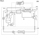
- Fig. 4 is a diagram showing an internal configuration of a refrigeration cycle apparatus 100A according to the second embodiment. As shown in Fig. 4 , refrigeration cycle apparatus 100A is different from refrigeration cycle apparatus 100 shown in Fig. 1 in including a pressure sensor 33.
- Pressure sensor 33 measures an intermediate pressure P2 which is a pressure at injection port 1p of compressor 1 and outputs a result of measurement to control device 70.
- Fig. 5 is a flowchart showing an exemplary flow in processing by control device 70 according to the second embodiment.
- Control device 70 performs a flow shown in Fig. 5 in parallel to the flow shown in Fig. 3 .
- control device 70 determines whether or not solenoid valve 14 is closed (step S11). When solenoid valve 14 is open (NO in step S11), control device 70 has the process return to step S11.
- control device 70 compares discharge pressure P1 of compressor 1 and a threshold value Th3 with each other and compares intermediate pressure P2 of compressor 1 and a threshold value Th4 with each other. Control device 70 determines whether or not at least one of a condition (1) and a condition (2) below is satisfied (step S12).
- control device 70 When neither of the condition (1) and the condition (2) is satisfied (NO in step S12), control device 70 has the process return to step S11.
- control device 70 controls solenoid valve 14 to open (step S13).
- solenoid valve 14 As solenoid valve 14 is opened, gas refrigerant is discharged from gas-liquid separator 7 and storage of liquid refrigerant in gas-liquid separator 7 is promoted.
- the amount of refrigerant in main circuit 50 thus decreases and discharge pressure P1 and intermediate pressure P2 lower. Consequently, even in transient operations until the stable state is reached, abrupt increase in pressure of refrigerant in main circuit 50 can be suppressed.
- discharge pressure P1 of compressor 1 lowers.
- discharge pressure P1 lowers, a compressed state (which is referred to as "overcompression” below) in which intermediate pressure P2 at injection port 1p becomes higher than discharge pressure P1 may occur in compressor 1.
- a refrigeration cycle apparatus solves also such a problem.
- Fig. 6 is a diagram showing an exemplary internal configuration of a refrigeration cycle apparatus 100B according to the third embodiment.
- refrigeration cycle apparatus 100B is different from refrigeration cycle apparatus 100 shown in Fig. 1 in including a pipe 18, solenoid valves 19 and 20, a capillary tube 22, a pressure sensor 34, and a temperature sensor 35.
- Pipe 18, solenoid valves 19 and 20, and capillary tube 22 are included in injection circuit 60.
- Pipe 18 connects a branch point 21 of pipe 10 and inlet 1i of compressor 1 in main circuit 50 to each other. In other words, pipe 18 allows flow of some of refrigerant that flows through pipe 10 toward a suction side of compressor 1. Branch point 21 is located between economizer 12 and injection port 1p.
- Solenoid valve 19 is provided in pipe 10 between branch point 21 and injection port 1p.
- Solenoid valve 20 is provided in pipe 18. Solenoid valve 19 or 20 is in any of an open state and a closed state.
- Capillary tube 22 is provided in pipe 18 between branch point 21 and solenoid valve 20. Capillary tube 22 decompresses refrigerant diverted from pipe 10.
- Pressure sensor 34 measures a suction pressure P3 which is a pressure of refrigerant on the suction side of compressor 1 and outputs a result of measurement to control device 70.
- Temperature sensor 35 measures an outdoor air temperature AT and outputs a result of measurement to control device 70.
- Fig. 7 is a flowchart showing an exemplary flow in processing by control device 70 according to the third embodiment.
- Control device 70 performs a flow shown in Fig. 7 in parallel to the flow shown in Fig. 3 .
- control device 70 determines whether or not solenoid valve 14 is open (step S21).
- control device 70 determines whether or not outdoor air temperature AT is lower than a threshold value Th5 (step S22).
- Threshold value Th5 is set, for example, to 0°C.
- control device 70 compares a compression ratio P1/P3 which is a value calculated by dividing discharge pressure P1 by suction pressure P3 with a threshold value Th6 and determines whether or not a condition of P1/P3 ⁇ Th6 is satisfied (step S23).
- Threshold value Th6 is determined in advance so as to be slightly larger than the compression ratio at the time when overcompression occurs, and is set, for example, to 1.4.
- control device 70 controls solenoid valves 14 and 19 to close and controls solenoid valve 20 to open (step S24).
- solenoid valve 14 As solenoid valve 14 is closed, gas refrigerant is no longer discharged from gas-liquid separator 7 and discharge of liquid refrigerant from gas-liquid separator 7 is promoted.
- solenoid valve 19 As solenoid valve 19 is closed, the backflow of refrigerant from injection port 1p to gas-liquid separator 7 can be prevented even on the occurrence of overcompression due to low outdoor air temperature AT.
- solenoid valve 20 is opened, refrigerant discharged from gas-liquid separator 7 passes through pipe 18 and returns to main circuit 50. The amount of refrigerant in main circuit 50 thus increases and occurrence of overcompression can be suppressed.
- Refrigerant that passes through pipe 18 is decompressed by capillary tube 22. Therefore, a pressure difference of refrigerant at a point of merge between pipe 18 and a pipe which composes main circuit 50 can be made smaller.
- a difference between the pressure of refrigerant upstream from solenoid valve 20 in pipe 18 and the pressure of refrigerant suctioned into compressor 1 is large, refrigerant suddenly flows from pipe 18 into main circuit 50 as a result of opening of solenoid valve 20. Occurrence of such sudden flow-in of refrigerant may cause frothing of liquid refrigerant stored in gas-liquid separator 7.
- liquid refrigerant may be discharged from pipe 9 provided in the upper portion of gas-liquid separator 7 due to such frothing.
- capillary tube 22 As capillary tube 22 is provided, however, such frothing and discharge of liquid refrigerant through pipe 9 are suppressed.
- capillary tube 22 does not have to be provided.
- control device 70 determines whether or not solenoid valve 20 is open (step S25). When solenoid valve 20 is closed (NO in step S25), control device 70 has the process return to step S21.
- control device 70 determines whether or not outdoor air temperature AT is lower than threshold value Th5 (step S26). When the condition of AT ⁇ Th5 is satisfied (YES in step S26), control device 70 compares compression ratio P1/P3 with threshold value Th6 and determines whether or not the condition of P1/P3 ⁇ Th6 is satisfied (step S27). When the condition of P1/P3 ⁇ Th6 is satisfied (YES in step S27), control device 70 has the process return to step S21.
- control device 70 controls solenoid valves 14 and 19 to open and controls solenoid valve 20 to close (step S28).
- determination as NO is made in step S26 or when determination as NO is made in step S27, possibility of occurrence of overcompression due to low outdoor air temperature AT is low. Therefore, as solenoid valve 14 is opened, gas refrigerant is discharged from gas-liquid separator 7. As solenoid valve 19 is opened and solenoid valve 20 is closed, refrigerant flows into injection port 1p, power consumption is reduced, and capability is improved.
- the refrigeration cycle apparatus determines whether or not the amount of refrigerant in main circuit 50 is excessive or insufficient based on degree of supercooling SC of refrigerant that has passed through condenser 2.
- a refrigeration cycle apparatus determines whether or not the amount of refrigerant in main circuit 50 is excessive or insufficient based on an evaporation temperature ET of refrigerant suctioned into compressor 1 and a liquid level in gas-liquid separator 7.
- Fig. 8 is a diagram showing an exemplary internal configuration of a refrigeration cycle apparatus 100C according to the fourth embodiment.
- refrigeration cycle apparatus 100C is different from refrigeration cycle apparatus 100 shown in Fig. 1 in including pressure sensor 34 and a liquid level sensor 36 instead of pressure sensor 31 and temperature sensor 32.
- Pressure sensor 34 measures suction pressure P3 of compressor 1 and outputs a result of measurement to control device 70 as described in the third embodiment.
- Liquid level sensor 36 is a sensor to sense a liquid level (a height of a liquid surface) in gas-liquid separator 7. Liquid level sensor 36 outputs a result of sensing to control device 70.
- Control device 70 calculates evaporation temperature ET of refrigerant suctioned into compressor 1 based on suction pressure P3.
- Control device 70 stores in advance a correspondence table in which a plurality of evaporation temperature zones and a plurality of height ranges are brought in correspondence, respectively.
- Control device 70 identifies an evaporation temperature zone to which evaporation temperature ET belongs among the plurality of evaporation temperature zones and determines as a subject height range, a height range corresponding to the identified evaporation temperature zone among the plurality of height ranges.
- Control device 70 controls the opening of flow rate regulation valve 13 and the open and closed state of solenoid valve 14 such that the liquid level in gas-liquid separator 7 is accommodated within the subject height range.
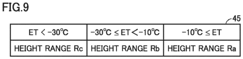
- Fig. 9 is a diagram showing an exemplary correspondence table 45 stored in control device 70 according to the fourth embodiment.
- correspondence table 45 an evaporation temperature zone lower than -30°C and a height range Rc are brought in correspondence with each other, an evaporation temperature zone not lower than -30°C and lower than -10°C and a height range Rb are brought in correspondence with each other, and an evaporation temperature zone not lower than -10°C and a height range Ra are brought in correspondence with each other.
- Fig. 10 is a diagram showing an exemplary height range set for gas-liquid separator 7 in the fourth embodiment.
- evaporation temperature ET is lower, an appropriate amount of refrigerant in main circuit 50 is smaller. Therefore, height range Rc corresponding to the evaporation temperature zone lower than -30°C is set to be higher than height range Rb corresponding to the evaporation temperature zone not lower than -30°C and lower than -10°C.
- height range Rb corresponding to the evaporation temperature zone not lower than -30°C and lower than -10°C is set to be higher than height range Ra corresponding to the evaporation temperature zone not lower than -10°C.
- the height range corresponding to the evaporation temperature zone lower in temperature of any two evaporation temperature zones selected from among the plurality of evaporation temperature zones is set to be higher than the height range corresponding to the evaporation temperature zone higher in temperature of the two evaporation temperature zones.
- the higher height range is set, the amount of liquid refrigerant stored in gas-liquid separator 7 becomes larger and the amount of refrigerant in main circuit 50 becomes smaller.
- the amount of refrigerant in main circuit 50 is adjusted to an appropriate amount.
- Refrigerant discharged from compressor 1 contains refrigerating machine oil of compressor 1. Therefore, refrigerating machine oil is contained also in liquid refrigerant stored in gas-liquid separator 7. Refrigerating machine oil discharged from compressor 1 is preferably collected in compressor 1. In an example where refrigerating machine oil is dissolved in refrigerant, refrigerating machine oil is collected in compressor 1 as liquid refrigerant is discharged from gas-liquid separator 7 through pipe 8. Alternatively, even in an example where refrigerating machine oil is not dissolved in refrigerant, so long as refrigerating machine oil is heavier in specific gravity than refrigerant, refrigerating machine oil is stored in the lower portion of gas-liquid separator 7.
- Refrigerating machine oil stored in the lower portion of gas-liquid separator 7 is discharged through pipe 8 and collected in compressor 1.
- refrigerating machine oil is stored in a form of a layer over liquid refrigerant in gas-liquid separator 7.
- liquid refrigerant is mainly discharged and refrigerating machine oil is less likely to be discharged through pipe 8. Therefore, refrigerating machine oil in gas-liquid separator 7 is less likely to be collected in compressor 1.
- Control device 70 controls the liquid level in gas-liquid separator 7 to reach a reference height LV (see Fig. 10 ) higher than one end 9a of pipe 9 every predetermined cycle in order to have refrigerating machine oil not dissolved in refrigerant and lighter in specific gravity than refrigerant collected in compressor 1.
- Fig. 11 is a diagram showing a state of gas-liquid separator 7 when the liquid level reaches reference height LV.
- one end 9a of pipe 9 is located in gas-liquid separator 7. Since the liquid level has reached reference height LV higher than one end 9a of pipe 9, one end 9a of pipe 9 is located within a layer 40 of refrigerating machine oil stored above liquid refrigerant. Refrigerating machine oil can thus be collected in compressor 1 through pipe 9.
- FIG. 12 is a flowchart showing a flow in steps S31 to S37 in processing by control device 70 according to the fourth embodiment.
- Fig. 13 is a flowchart showing a flow in steps S38 to S44 in processing by control device 70 according to the fourth embodiment.
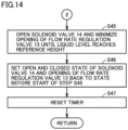
- Fig. 14 is a flowchart showing a flow in steps S45 to S47 in processing by control device 70 according to the fourth embodiment.
- control device 70 determines whether or not time T3 has elapsed since start-up or since the liquid refrigerant previously reached reference height LV (step S31).
- Time T3 is a cycle determined in advance, and set, for example, to sixty minutes.
- Control device 70 includes an internal timer for performing step S31, and at the time of start-up of refrigeration cycle apparatus 100C, it resets the internal timer and has the internal timer start counting. As the count value of the internal timer reaches time T3, control device 70 should only make determination as YES in step S31.
- control device 70 calculates evaporation temperature ET based on suction pressure P3 and determines whether or not a condition of ET ⁇ -30°C is satisfied (step S32). When the condition of ET ⁇ -30°C is not satisfied (NO in step S32), control device 70 determines whether or not a condition of -30°C ⁇ ET ⁇ -10°C is satisfied (step S33).
- control device 70 reads height range Rc corresponding to the evaporation temperature zone lower than -30°C as the subject height range from correspondence table 45 shown in Fig. 9 . Control device 70 determines whether or not the liquid level sensed by liquid level sensor 36 belongs to the subject height range (step S34).
- control device 70 reads height range Rb corresponding to the evaporation temperature zone not lower than -30°C and lower than -10°C as the subject height range from correspondence table 45 shown in Fig. 9 .
- Control device 70 determines whether or not the liquid level sensed by liquid level sensor 36 belongs to the subject height range (step S35).
- control device 70 reads height range Ra corresponding to the evaporation temperature zone not lower than -10°C as the subject height range from correspondence table 45 shown in Fig. 9 . Control device 70 determines whether or not the liquid level sensed by liquid level sensor 36 belongs to the subject height range (step S36).
- control device 70 When determination as YES is made in steps S34, S35, and S36, control device 70 maintains the opening of flow rate regulation valve 13 in the current state (step S37). After step S37, control device 70 has the process return to step S31.
- control device 70 determines whether or not the liquid level exceeds an upper limit of the subject height range (step S38).
- control device 70 determines whether or not the opening of flow rate regulation valve 13 is maximum (step S39).
- control device 70 increases the opening of flow rate regulation valve 13 by one level (step S40). The amount of refrigerant that flows through pipe 8 thus increases and liquid refrigerant is more likely to be discharged from gas-liquid separator 7. Consequently, the liquid level comes closer to the subject height range and the amount of refrigerant in main circuit 50 increases.
- control device 70 has the process return to step S31.
- control device 70 controls solenoid valve 14 to close (step S41).
- solenoid valve 14 As solenoid valve 14 is closed, gas refrigerant is stored in gas-liquid separator 7 and discharge of liquid refrigerant is promoted. Consequently, the liquid level comes closer to the subject height range and the amount of refrigerant in main circuit 50 increases.
- control device 70 After step S41, control device 70 has the process return to step S31.
- control device 70 determines whether or not the opening of flow rate regulation valve 13 is minimum (step S42). When the opening of flow rate regulation valve 13 is not minimum (NO in step S42), control device 70 decreases the opening of flow rate regulation valve 13 by one level (step S43). The amount of refrigerant that flows through pipe 8 thus decreases and liquid refrigerant is more likely to be stored in gas-liquid separator 7. Consequently, the liquid level comes closer to the subject height range and the amount of refrigerant in main circuit 50 decreases. After step S43, control device 70 has the process return to step S31.
- control device 70 controls solenoid valve 14 to open (step S43).
- solenoid valve 14 As solenoid valve 14 is opened, gas refrigerant is discharged from gas-liquid separator 7 and liquid refrigerant is further more likely to be stored in gas-liquid separator 7. Consequently, the liquid level comes closer to the subject height range and the amount of refrigerant in main circuit 50 increases.
- control device 70 After step S43, control device 70 has the process return to step S31.
- control device 70 controls solenoid valve 14 to open and minimizes the opening of flow rate regulation valve 13 (that is, controls flow rate regulation valve 13 to close) until the liquid level reaches reference height LV (step S45).
- flow rate regulation valve 13 is closed, discharge of liquid refrigerant from gas-liquid separator 7 is stopped.
- solenoid valve 14 is opened, gas refrigerant is discharged from gas-liquid separator 7 and storage of liquid refrigerant in gas-liquid separator 7 is promoted.
- reference height LV is higher than one end of pipe 9. Therefore, layer 40 of refrigerating machine oil is discharged through pipe 9 and refrigerating machine oil is collected in compressor 1 by the time when the liquid level reaches reference height LV after it reaches one end of pipe 9.
- Control device 70 may stand by for a certain time period after the liquid level reaches reference height LV. Refrigerating machine oil in gas-liquid separator 7 is thus more reliably collected in compressor 1.
- control device 70 sets the opening of flow rate regulation valve 13 and the open and closed state of solenoid valve 14 back to a state before start of step S45 (step S46). Then, control device 70 resets the internal timer used for performing step S31 (step S47). Thus, step S45 is performed each time time T3 elapses and refrigerating machine oil in gas-liquid separator 7 is periodically collected in compressor 1.
- Refrigeration cycle apparatus 100C determines whether or not the amount of refrigerant in main circuit 50 is excessive or insufficient based on evaporation temperature ET of refrigerant suctioned into compressor 1 and the height of the liquid surface in gas-liquid separator 7.
- a refrigeration cycle apparatus determines whether or not the amount of refrigerant in main circuit 50 is excessive or insufficient based on the outdoor air temperature, evaporation temperature ET, and the height of the liquid surface in gas-liquid separator 7.
- control device 70 determines the subject height range based on outdoor air temperature AT and evaporation temperature ET and controls the opening of flow rate regulation valve 13 and the open and closed state of solenoid valve 14 such that the liquid level in gas-liquid separator 7 is accommodated within the subject height range.
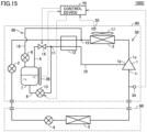
- Fig. 15 is a diagram showing an exemplary internal configuration of a refrigeration cycle apparatus 100D according to the fifth embodiment. As shown in Fig. 15 , refrigeration cycle apparatus 100D is different from refrigeration cycle apparatus 100C shown in Fig. 8 in further including temperature sensor 35. Temperature sensor 35 measures outdoor air temperature AT and outputs a result of measurement to control device 70 as described in the third embodiment.
- Control device 70 stores in advance a correspondence table in which a plurality of evaporation temperature zones and a plurality of height ranges are brought in correspondence, respectively, for each of a plurality of outdoor air temperature zones.
- Fig. 16 is a diagram showing an exemplary correspondence table 46 stored in control device 70 according to the fifth embodiment.
- correspondence table 46 includes a record 46a corresponding to an outdoor air temperature zone not lower than 10°C and a record 46b corresponding to an outdoor air temperature zone lower than 10°C.
- each of the evaporation temperature zone lower than -30°C, the evaporation temperature zone not lower than -30°C and lower than -10°C, and the evaporation temperature zone not lower than -10°C is brought in correspondence with the height range.
- each of records 46a and 46b is correspondence information in which the plurality of evaporation temperature zones and the plurality of height ranges are brought in correspondence, respectively.
- the evaporation temperature zone lower than -30°C is brought in correspondence with a height range Rf
- the evaporation temperature zone not lower than -30°C and lower than -10°C is brought in correspondence with a height range Re
- the evaporation temperature zone not lower than -10°C is brought in correspondence with a height range Rd.
- the evaporation temperature zone lower than -30°C is brought in correspondence with a height range Ri
- the evaporation temperature zone not lower than -30°C and lower than -10°C is brought in correspondence with a height range Rh
- the evaporation temperature zone not lower than -10°C is brought in correspondence with a height range Rg.
- Fig. 17 is a diagram showing an exemplary height range set for gas-liquid separator 7 in the fifth embodiment.
- evaporation temperature ET is lower, an appropriate amount of refrigerant in main circuit 50 is smaller. Therefore, height ranges Rf and Ri corresponding to the evaporation temperature zone lower than -30°C are set to be higher than height ranges Re and Rh corresponding to the evaporation temperature zone not lower than -30°C and lower than -10°C, respectively. Similarly, height ranges Re and Rh corresponding to the evaporation temperature zone not lower than -30°C and lower than -10°C are set to be higher than height ranges Rd and Rg corresponding to the evaporation temperature zone not lower than -10°C, respectively. As the higher height range is set, the amount of liquid refrigerant stored in gas-liquid separator 7 becomes larger and the amount of refrigerant in main circuit 50 becomes smaller.
- height ranges Rf, Re, and Rd corresponding to the outdoor air temperature zone not lower than 10°C are set to be lower than height ranges Ri, Rh, and Rg corresponding to the outdoor air temperature zone lower than 10°C.
- a plurality of height ranges included in a record corresponding to an outdoor air temperature zone higher in temperature of any two outdoor air temperature zones selected from among the plurality of outdoor air temperature zones are set to be lower than a plurality of height ranges included in a record corresponding to an outdoor air temperature zone lower in temperature of the two outdoor air temperature zones.
- Fig. 18 is a flowchart showing a flow in steps S51 to S59 in processing by control device 70 according to the fifth embodiment.
- control device 70 determines whether or not time T3 has elapsed since start-up or since the liquid level previously reached reference height LV (step S51). Details of step S51 are the same as those of step S31 shown in Fig. 12 .
- control device 70 determines whether or not outdoor air temperature AT received from temperature sensor 35 satisfies a condition of AT ⁇ 10°C (step S52).
- control device 70 reads record 46b corresponding to the outdoor air temperature zone lower than 10°C in correspondence table 46 shown in Fig. 16 (S53).
- control device 70 calculates evaporation temperature ET based on suction pressure P3 and determines whether or not the condition of ET ⁇ -30°C is satisfied (step S54). When the condition of ET ⁇ -30°C is not satisfied (NO in step S54), control device 70 determines whether or not the condition of -30°C ⁇ ET ⁇ -10°C is satisfied (step S55).
- control device 70 reads height range Ri corresponding to the evaporation temperature zone lower than -30°C as the subject height range from record 46b read in step S53. Control device 70 determines whether or not the liquid level sensed by liquid level sensor 36 belongs to the subject height range (step S56).
- control device 70 reads height range Rh corresponding to the evaporation temperature zone not lower than -30°C and lower than -10°C as the subject height range from record 46b read in step S53. Control device 70 determines whether or not the liquid level sensed by liquid level sensor 36 belongs to the subject height range (step S57).
- control device 70 reads height range Rg corresponding to the evaporation temperature zone not lower than -10°C as the subject height range from record 46b read in step S53. Control device 70 determines whether or not the liquid level sensed by liquid level sensor 36 belongs to the subject height range (step S58).
- control device 70 When determination as YES is made in steps S56 to S58, control device 70 maintains the opening of flow rate regulation valve 13 in the current state (step S59). After step S59, control device 70 has the process return to step S51.
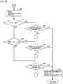
- Fig. 19 is a flowchart showing a flow in steps S60 to S66 in processing by control device 70 according to the fifth embodiment.
- control device 70 reads record 46a corresponding to the outdoor air temperature zone not lower than 10°C in correspondence table 46 shown in Fig. 16 (S60).
- control device 70 calculates evaporation temperature ET based on suction pressure P3 and determines whether or not the condition of ET ⁇ -30°C is satisfied (step S61). When the condition of ET ⁇ -30°C is not satisfied (NO in step S61), control device 70 determines whether or not the condition of -30°C ⁇ ET ⁇ -10°C is satisfied (step S62).
- control device 70 reads height range Rf corresponding to the evaporation temperature zone lower than -30°C as the subject height range from record 46a read in step S60. Control device 70 determines whether or not the liquid level sensed by liquid level sensor 36 belongs to the subject height range (step S63).
- control device 70 reads height range Re corresponding to the evaporation temperature zone not lower than -30°C and lower than -10°C as the subject height range from record 46a read in step S59. Control device 70 determines whether or not the liquid level sensed by liquid level sensor 36 belongs to the subject height range (step S64).
- control device 70 reads height range Rd corresponding to the evaporation temperature zone not lower than -10°C as the subject height range from record 46a read in step S59. Control device 70 determines whether or not the liquid level sensed by liquid level sensor 36 belongs to the subject height range (step S65).
- control device 70 When determination as YES is made in steps S63 to S65, control device 70 maintains the opening of flow rate regulation valve 13 in the current state (step S66). After step S66, control device 70 has the process return to step S51.
- control device 70 When determination as NO is made in steps S56 to S58 and S63 to S65, control device 70 performs steps S38 to S44 shown in Fig. 13 and thereafter has the process return to step S51 as in the fourth embodiment.
- step S51 When determination as YES is made in step S51, steps S45 to S47 shown in Fig. 14 are performed and thereafter the process returns to step S51 as in the fourth embodiment.
- economizer 12 exchanges heat between refrigerant that flows through pipe 10 and refrigerant that flows out of condenser 2.
- economizer 12 exchanges heat between refrigerant that flows through pipe 9 and refrigerant that flows out of condenser 2.
- Fig. 20 is a diagram showing an internal configuration of a refrigeration cycle apparatus 100E according to the sixth embodiment.
- economizer 12 is arranged in pipe 9 between solenoid valve 14 and point of merge 11.
- Pipe 8 does not pass through economizer 12 but merges with pipe 9 at point of merge 11.
- wetness of refrigerant in a gas-liquid two-phase state that flows into injection port 1p of compressor 1 is high and capability to lower a temperature of refrigerant discharged from compressor 1 can be enhanced.
- a degree of wetness of refrigerant in the gas-liquid two-phase state is adjusted by the opening of flow rate regulation valve 13 provided in pipe 8.
- economizer 12 exchanges heat between refrigerant that flows through pipe 8 and refrigerant that flows out of condenser 2.
- Fig. 21 is a diagram showing an internal configuration of a refrigeration cycle apparatus 100F according to the seventh embodiment.
- economizer 12 is arranged in pipe 8 between flow rate regulation valve 13 and point of merge 11.
- Pipe 9 does not pass through economizer 12 but merges with pipe 8 at point of merge 11.
- economizer 12 can enhance efficiency in heat exchange by making use of evaporation latent heat of liquid refrigerant that flows through pipe 8.
- a refrigeration cycle apparatus can switch a path in injection circuit 60 shown in Figs. 1 , 20 , and 21 .
- Fig. 22 is a diagram showing an internal configuration of a refrigeration cycle apparatus 100G according to the eighth embodiment. As shown in Fig. 22 , refrigeration cycle apparatus 100G is different from refrigeration cycle apparatus 100 shown in Fig. 1 in including pipes 23 to 30 and three-way valves 47 and 48.
- Three-way valve 47 includes three ports 47a, 47b, and 47c, and switches between a state in which port 47a and port 47b communicate with each other and a state in which port 47a and port 47c communicate with each other.
- Three-way valve 48 includes three ports 48a, 48b, and 48c, and switches between a state in which port 48a and port 48b communicate with each other and a state in which port 48a and port 48c communicate with each other.
- Pipe 23 is provided to discharge liquid refrigerant from gas-liquid separator 7.
- Pipe 23 connects gas-liquid separator 7 and port 47a of three-way valve 47 to each other.
- Flow rate regulation valve 13 is provided in pipe 23.
- Pipe 24 has one end connected to port 47b of three-way valve 47.
- Pipe 25 has one end connected to port 47c of three-way valve 47.
- Pipe 26 is provided to discharge gas refrigerant from gas-liquid separator 7.
- Pipe 26 connects gas-liquid separator 7 and port 48a of three-way valve 48 to each other.
- Solenoid valve 14 is provided in pipe 26.
- Pipe 27 has one end connected to port 48b of three-way valve 48.
- Pipe 28 has one end connected to port 48c of three-way valve 48.
- Pipe 25 has the other end connected to the other end of pipe 27.
- Pipe 25 has the other end connected to the other end of pipe 28.
- Pipe 29 connects a point of connection 11a between pipes 24 and 27 to a point of connection 11b between pipes 25 and 28.
- Pipe 29 passes through economizer 12. Therefore, heat is exchanged between refrigerant that flows through pipe 29 and refrigerant that has passed through condenser 2.
- Pipe 30 connects point of connection 11b between pipes 25 and 28 to injection port 1p of compressor 1.
- Control device 70 switches three-way valves 47 and 48 to any one of first to third states below.
- refrigerant that has passed through flow rate regulation valve 13 flows to point of connection 11b.
- Refrigerant that has passed through solenoid valve 14 passes through pipes 27 and 29 and flows to point of connection 11b.
- refrigerant that has passed through solenoid valve 14 exchanges heat with refrigerant that has passed through condenser 2 in economizer 12, and thereafter merges, at point of connection 11b, with refrigerant that has passed through flow rate regulation valve 13.
- Refrigerant that has passed through flow rate regulation valve 13 does not pass through economizer 12.
- Refrigerant that merges at point of connection 11b flows through pipe 30 to compressor 1. The path in injection circuit 60 in the sixth embodiment is thus realized.
- pipes 23 and 25 compose pipe 8 in Fig. 20
- pipes 26, 27, and 29 compose pipe 9 in Fig. 20
- pipe 30 composes pipe 10 in Fig. 20
- Point of connection 11b corresponds to point of merge 11 in Fig. 20 .
- refrigerant that has passed through solenoid valve 14 flows to point of connection 11b.
- Refrigerant that has passed through flow rate regulation valve 13 passes through pipes 24 and 29 and flows to point of connection 11b.
- refrigerant that has passed through flow rate regulation valve 13 exchanges heat with refrigerant that has passed through condenser 2 in economizer 12, and thereafter merges, at point of connection 11b, with refrigerant that has passed through solenoid valve 14.
- Refrigerant that has passed through solenoid valve 14 does not pass through economizer 12.
- Refrigerant that merges at point of connection 11b flows through pipe 30 to compressor 1. The path in injection circuit 60 in the seventh embodiment is thus realized.
- pipes 23, 24, and 29 compose pipe 8 in Fig. 21
- pipes 26 and 28 compose pipe 9 in Fig. 21
- pipe 30 composes pipe 10 in Fig. 21
- Point of connection 11b corresponds to point of merge 11 in Fig. 21 .
- Three-way valves 47 and 48 thus switch the pipe that passes through economizer 12 to any one of pipe 8, pipe 9, and pipe 10.
- control device 70 should only set three-way valves 47 and 48 to the first state except for the case of transient variation in discharge temperature of compressor 1. Then, control device 70 should only switch three-way valves 47 and 48 to the second state when the discharge temperature of compressor 1 abruptly increases (for example, to 115°C or higher). Furthermore, when the discharge temperature lowers and superheat of discharged refrigerant has not yet been secured (for example, superheat is equal to or lower than 20 K), control device 70 should only switch three-way valves 47 and 48 to the third state.
- pipe 18, solenoid valves 19 and 20, and capillary tube 22 may be provided in injection circuit 60 as in the third embodiment.
- liquid level sensor 36 senses the liquid level in gas-liquid separator 7. Therefore, in order to accurately sense the liquid level, the liquid surface is preferably stable in gas-liquid separator 7.
- capillary tube 22 is provided between branch point 21 and solenoid valve 20. As capillary tube 22 is provided, frothing of liquid refrigerant stored in gas-liquid separator 7 can be suppressed as described above. Consequently, the liquid surface is stabilized in gas-liquid separator 7 and liquid level sensor 36 can accurately sense the liquid level.
Landscapes
- Engineering & Computer Science (AREA)
- Physics & Mathematics (AREA)
- Mechanical Engineering (AREA)
- Thermal Sciences (AREA)
- General Engineering & Computer Science (AREA)
- Air Conditioning Control Device (AREA)
Applications Claiming Priority (1)
| Application Number | Priority Date | Filing Date | Title |
|---|---|---|---|
| PCT/JP2020/046094 WO2022123736A1 (fr) | 2020-12-10 | 2020-12-10 | Dispositif à cycle de réfrigération |
Publications (2)
| Publication Number | Publication Date |
|---|---|
| EP4261475A1 true EP4261475A1 (fr) | 2023-10-18 |
| EP4261475A4 EP4261475A4 (fr) | 2023-12-27 |
Family
ID=81973422
Family Applications (1)
| Application Number | Title | Priority Date | Filing Date |
|---|---|---|---|
| EP20965118.1A Pending EP4261475A4 (fr) | 2020-12-10 | 2020-12-10 | Dispositif à cycle de réfrigération |
Country Status (3)
| Country | Link |
|---|---|
| EP (1) | EP4261475A4 (fr) |
| JP (1) | JP7433476B2 (fr) |
| WO (1) | WO2022123736A1 (fr) |
Families Citing this family (3)
| Publication number | Priority date | Publication date | Assignee | Title |
|---|---|---|---|---|
| CN115264643B (zh) * | 2022-07-18 | 2025-11-14 | 青岛海信日立空调系统有限公司 | 一种空调系统及其控制方法 |
| JP7670996B2 (ja) * | 2023-03-31 | 2025-05-01 | ダイキン工業株式会社 | 冷凍装置 |
| CN119778898B (zh) * | 2024-12-30 | 2025-09-23 | 哈尔滨工业大学 | 一种蒸气压缩式热泵系统控制及蒸气压缩式热泵系统 |
Family Cites Families (6)
| Publication number | Priority date | Publication date | Assignee | Title |
|---|---|---|---|---|
| DK2147264T3 (en) * | 2007-04-24 | 2019-03-04 | Carrier Corp | Refrigerant vapor compression system |
| US8671703B2 (en) * | 2007-05-14 | 2014-03-18 | Carrier Corporation | Refrigerant vapor compression system with flash tank economizer |
| JP2010127531A (ja) | 2008-11-27 | 2010-06-10 | Mitsubishi Electric Corp | 冷凍空調装置 |
| JP6420686B2 (ja) | 2015-02-24 | 2018-11-07 | 日立ジョンソンコントロールズ空調株式会社 | 冷凍サイクル装置 |
| JP6472527B2 (ja) * | 2015-08-28 | 2019-02-20 | 三菱電機株式会社 | 冷凍サイクル装置 |
| US11473814B2 (en) * | 2019-05-13 | 2022-10-18 | Heatcraft Refrigeration Products Llc | Integrated cooling system with flooded air conditioning heat exchanger |
-
2020
- 2020-12-10 WO PCT/JP2020/046094 patent/WO2022123736A1/fr not_active Ceased
- 2020-12-10 EP EP20965118.1A patent/EP4261475A4/fr active Pending
- 2020-12-10 JP JP2022567979A patent/JP7433476B2/ja active Active
Also Published As
| Publication number | Publication date |
|---|---|
| JPWO2022123736A1 (fr) | 2022-06-16 |
| JP7433476B2 (ja) | 2024-02-19 |
| EP4261475A4 (fr) | 2023-12-27 |
| WO2022123736A1 (fr) | 2022-06-16 |
Similar Documents
| Publication | Publication Date | Title |
|---|---|---|
| EP2320159A1 (fr) | Dispositif de réfrigération | |
| EP4261475A1 (fr) | Dispositif à cycle de réfrigération | |
| JP4888500B2 (ja) | 冷凍装置 | |
| JP6134477B2 (ja) | 冷凍装置及び冷凍機ユニット | |
| EP4137756A1 (fr) | Unité de source de chaleur, dispositif à cycle de réfrigération et réfrigérateur | |
| EP2317250B1 (fr) | Dispositif de réfrigération | |
| EP3106779A1 (fr) | Dispositif de réfrigération | |
| EP3282208B1 (fr) | Appareil de réfrigération | |
| JP2013155972A (ja) | 冷凍装置 | |
| JP6490237B2 (ja) | 冷媒量管理装置及び冷媒量管理システム | |
| KR100614364B1 (ko) | 냉동 장치 | |
| CN101223405A (zh) | 冷冻装置 | |
| JP4868049B2 (ja) | 冷凍装置 | |
| US20090077985A1 (en) | Refrigerating Apparatus | |
| JP6112388B2 (ja) | 冷凍装置 | |
| JP6094859B2 (ja) | 冷凍装置 | |
| JP7367222B2 (ja) | 冷凍サイクル装置 | |
| JP2015068571A (ja) | 冷凍装置 | |
| JP7412639B2 (ja) | 熱源ユニット | |
| JP2019128050A (ja) | コンデンシングユニット、冷凍装置、及び制御方法 | |
| JP7661154B2 (ja) | 冷凍装置及び冷凍システム並びに冷凍装置の制御方法 | |
| EP3486578A1 (fr) | Dispositif de réfrigération | |
| EP4685414A1 (fr) | Dispositif de commande, unité de condensation, procédé de commande et programme de commande | |
| JP7466645B2 (ja) | 冷凍サイクル装置 | |
| JPS63286664A (ja) | ヒ−トポンプ式空気調和機 |
Legal Events
| Date | Code | Title | Description |
|---|---|---|---|
| STAA | Information on the status of an ep patent application or granted ep patent |
Free format text: STATUS: THE INTERNATIONAL PUBLICATION HAS BEEN MADE |
|
| PUAI | Public reference made under article 153(3) epc to a published international application that has entered the european phase |
Free format text: ORIGINAL CODE: 0009012 |
|
| STAA | Information on the status of an ep patent application or granted ep patent |
Free format text: STATUS: REQUEST FOR EXAMINATION WAS MADE |
|
| 17P | Request for examination filed |
Effective date: 20230425 |
|
| AK | Designated contracting states |
Kind code of ref document: A1 Designated state(s): AL AT BE BG CH CY CZ DE DK EE ES FI FR GB GR HR HU IE IS IT LI LT LU LV MC MK MT NL NO PL PT RO RS SE SI SK SM TR |
|
| REG | Reference to a national code |
Ref country code: DE Ref legal event code: R079 Free format text: PREVIOUS MAIN CLASS: F25B0001000000 Ipc: F25B0041000000 |
|
| A4 | Supplementary search report drawn up and despatched |
Effective date: 20231123 |
|
| RIC1 | Information provided on ipc code assigned before grant |
Ipc: F25B 49/02 20060101ALI20231117BHEP Ipc: F25B 41/39 20210101ALI20231117BHEP Ipc: F25B 41/00 20210101AFI20231117BHEP |
|
| DAV | Request for validation of the european patent (deleted) | ||
| DAX | Request for extension of the european patent (deleted) | ||
| STAA | Information on the status of an ep patent application or granted ep patent |
Free format text: STATUS: EXAMINATION IS IN PROGRESS |
|
| 17Q | First examination report despatched |
Effective date: 20251111 |