EP4261485A1 - Système de traitement pour pâtes alimentaires à coupe longue - Google Patents
Système de traitement pour pâtes alimentaires à coupe longue Download PDFInfo
- Publication number
- EP4261485A1 EP4261485A1 EP23167688.3A EP23167688A EP4261485A1 EP 4261485 A1 EP4261485 A1 EP 4261485A1 EP 23167688 A EP23167688 A EP 23167688A EP 4261485 A1 EP4261485 A1 EP 4261485A1
- Authority
- EP
- European Patent Office
- Prior art keywords
- long
- section
- pasta
- trajectory
- air flow
- Prior art date
- Legal status (The legal status is an assumption and is not a legal conclusion. Google has not performed a legal analysis and makes no representation as to the accuracy of the status listed.)
- Granted
Links
Images

Classifications
-
- A—HUMAN NECESSITIES
- A21—BAKING; EDIBLE DOUGHS
- A21D—TREATMENT OF FLOUR OR DOUGH FOR BAKING, e.g. BY ADDITION OF MATERIALS; BAKING; BAKERY PRODUCTS
- A21D8/00—Methods for preparing or baking dough
- A21D8/02—Methods for preparing dough; Treating dough prior to baking
-
- F—MECHANICAL ENGINEERING; LIGHTING; HEATING; WEAPONS; BLASTING
- F26—DRYING
- F26B—DRYING SOLID MATERIALS OR OBJECTS BY REMOVING LIQUID THEREFROM
- F26B15/00—Machines or apparatus for drying objects with progressive movement; Machines or apparatus with progressive movement for drying batches of material in compact form
- F26B15/10—Machines or apparatus for drying objects with progressive movement; Machines or apparatus with progressive movement for drying batches of material in compact form with movement in a path composed of one or more straight lines, e.g. compound, the movement being in alternate horizontal and vertical directions
- F26B15/12—Machines or apparatus for drying objects with progressive movement; Machines or apparatus with progressive movement for drying batches of material in compact form with movement in a path composed of one or more straight lines, e.g. compound, the movement being in alternate horizontal and vertical directions the lines being all horizontal or slightly inclined
- F26B15/122—Machines or apparatus for drying objects with progressive movement; Machines or apparatus with progressive movement for drying batches of material in compact form with movement in a path composed of one or more straight lines, e.g. compound, the movement being in alternate horizontal and vertical directions the lines being all horizontal or slightly inclined the objects or batches of material being carried by transversely moving rollers or rods which may rotate
- F26B15/126—Machines or apparatus for drying objects with progressive movement; Machines or apparatus with progressive movement for drying batches of material in compact form with movement in a path composed of one or more straight lines, e.g. compound, the movement being in alternate horizontal and vertical directions the lines being all horizontal or slightly inclined the objects or batches of material being carried by transversely moving rollers or rods which may rotate the material being "pasta" products, e.g. spaghetti
-
- F—MECHANICAL ENGINEERING; LIGHTING; HEATING; WEAPONS; BLASTING
- F26—DRYING
- F26B—DRYING SOLID MATERIALS OR OBJECTS BY REMOVING LIQUID THEREFROM
- F26B2210/00—Drying processes and machines for solid objects characterised by the specific requirements of the drying goods
- F26B2210/06—Long pasta, e.g. spaghetti
Definitions
- the present invention refers to a treatment system for long-cut pasta.
- long-cut pasta it is understood to mean pasta that has a threadlike or ribbon-like conformation, with a length much greater (at least 20 times greater) than its transversal extension, such as spaghetti, linguine, beideni, tagliatelle, etc.; it should also be noted that in the present text, even when not specified, the expression “pasta” will always refer to "long-cut pasta”.
- treatment systems for long-cut pasta comprising a drying device and a cooling device which is placed downstream of said drying device.
- the long-cut pasta once extruded, is typically loaded astride rods, the so-called “pipes”, arranged with their horizontal longitudinal axis, which are moved, perpendicularly to their longitudinal axis, inside the drying device and, subsequently, the cooling device.
- the pasta is subjected, for predetermined time intervals, to predetermined values of temperature and relative humidity, so that a desired amount of water is removed therefrom, and a desired stiffening is achieved (the so-called vitrification).
- solutions are known in which the pasta remains in a region of pre-drying of the drying device for a period of time lasting about 40-45 minutes, with indicative increasing temperature from 50 to 90°C, during which the average humidity percentage of pasta goes from about 28% to about 16-18%.
- the pasta then passes to a region of drying of the drying device, where it remains for a period of time equal to about 2 hours, in which its average humidity percentage drops to around 12-12.5%.
- the percentage of humidity in the central core of the pasta still remains at a higher value than the average humidity, and in particular higher than the humidity level on the external surface of the pasta.
- the pasta is then brought in a region of stabilisation of the drying device, where it is subjected for a certain time to predetermined values of temperature and relative humidity, such as to increase by a certain degree (usually about 2-3%) the humidity level on the external surface of the pasta, and thus bring it closer to the value of the humidity in the core thereof.
- the inlet of the cooling device is positioned spaced from the outlet of the drying device; in such known systems, the rods on which the pasta is loaded, once they have exited from the drying device, do not thus enter directly into the cooling device, but they are first passed through a transfer device that has the purpose of creating a discontinuity between the internal zone of the drying device and the internal zone of the cooling device and, at the same time, of allowing a continuity in the movement of the support elements between the two devices.
- the rods, and the pasta loaded on them are then introduced into the cooling device.
- the pasta By passing through the cooling device, the pasta is cooled in a controlled temperature environment, so that it exits from said cooling device at a temperature close to ambient temperature (generally comprised between 20 and 30°C) .
- the cooling along the cooling device must take place gradually, so as to ensure a good organoleptic and aesthetic quality to the final product.
- the gradual cooling is achieved with a slow cooling, guaranteed by a reduced temperature difference between the pasta and the surrounding air, throughout the cooling device.
- the pasta which exits from the drying device at a temperature equal to about 80°C, after passing through the transfer device (where it remains in contact with the external environment, at a temperature generally comprised between 20°C and 30°C, for a time comprised between 40 and 60 seconds, cooling down by at most 3-4°C) enters the cooling device at a still very high temperature, generally comprised between 75°C and 77°C, causing a high heating of the air inside said cooling device; this phenomenon is more accentuated in the initial section of the cooling device.
- the heating of the air inside the cooling device decreases its relative humidity, causing a high evaporation of the water contained in the pasta, which thus dries in an uncontrolled and potentially uneven manner; the high evaporation of the water contained in the pasta also causes an increase in the humidity of the air, which humidity then condenses in the zone of contact with the heat exchangers of the cooling device, in which cold water flows, which are generally positioned above the region in which the pasta passes, with the consequent problem of the condensation water dripping on the pasta, which causes visible aesthetic defects on the surface thereof, and the formation of water stagnations that can cause the generation of bad smells and result in corrosion problems.
- cooling device since gradual cooling, and hence a reduced temperature difference between the pasta and the surrounding air, must be ensured throughout the cooling device, as the temperature of the pasta entering the cooling device is quite high, said cooling device must be relatively very long (typically from 4 to 10 m, as a function of the production size), and therefore bulky and expensive.
- the main aim of the present invention is to solve the problems listed above, and therefore to realize a treatment system for long-cut pasta that allows to reduce the temperature of the long-cut pasta, and of the rods that support it, entering the cooling device, and consequently the temperature of the air inside the cooling device, in particular near the inlet region for pasta.
- an object of the present invention is to allow reducing the encumbrance, and consequently also the cost, of the cooling device of a treatment system for long-cut pasta with respect to the cited prior art.
- Another object of the present invention is to eliminate or reduce the consumption of nebulised water to lower the temperature of the air entering the cooling device.
- Yet another object is to reduce the energy consumption related to the decrease of the temperature of the water in the heat exchangers for cooling the air inside the cooling device.
- a further object of the present invention is to prevent a rapid and an uncontrolled evaporation of the humidity contained in the pasta from taking place within the cooling device, such that an excessive drying thereof is caused.
- a treatment system for long-cut pasta comprising:
- end portion substantially straight of the long-cut pasta is understood to mean a portion of the long-cut pasta (which has a threadlike or ribbon-like conformation) which starts from a free end thereof and extends longitudinally for a certain stretch, and is arranged along a straight or substantially straight line; in particular, when the long-cut pasta is hung on the support means, the first end portion is kept substantially straight and in a substantially vertical position by effect of the force of gravity acting thereon.
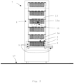
- the system rests on a horizontal surface 17, such as for example the floor of an industrial plant for the production of pasta.
- the treatment system 1 for long-cut pasta 2 comprises support means 3 for hanging long-cut pasta 2 in such a way that it protrudes from said support means 3 with at least one first end portion 4a of its, substantially straight and arranged in a substantially vertical position.
- end portion substantially straight of the long-cut pasta 2 it is understood to mean a portion of the long-cut pasta 2 (which has a threadlike or ribbon-like conformation) which starts from a free end thereof and extends longitudinally for a certain stretch, and is arranged along a straight or substantially straight line; in particular, when the long-cut pasta 2 is hung on the support means 3, the first end portion 4a is kept substantially straight and in a substantially vertical position by effect of the force of gravity acting thereon.
- the support means 3 comprise a plurality of rods 3a, substantially straight, preferably tubular in shape, preferably made of metallic material, such as for example anodized aluminium.
- the long-cut pasta 2 hanging on the support means 3 protrudes therefrom also with a second end portion 4b of its, substantially straight and arranged in a substantially vertical position; it is pointed out that when the long-cut pasta 2 is hung on the support means 3, the second end portion 4b is kept substantially straight and in a substantially vertical position by effect of the force of gravity acting thereon.
- the long-cut pasta 2 is hung on the support means 3 by folding said long-cut pasta 2 approximately in half, so as to assume, in a side view, like for example the one of Figure 1 , an approximately inverted "U" arrangement, in which the first end portion 4a and the second end portion 4b constitute the two arms of the "U", and are joined to each other by an intermediate, curved, portion 4c that engages with the support means 3 (in particular with a rod 3a in the case where the support means 3 comprise a plurality of rods 3a) .
- the system 1 comprises a drying device 5 (schematically represented in the accompanying figures as a rectangle), for drying and stabilising the long-cut pasta 2; such a drying device 5 is known in the field of the systems for the treatment of pasta, and will therefore not be described in detail.
- a drying device 5 (schematically represented in the accompanying figures as a rectangle), for drying and stabilising the long-cut pasta 2; such a drying device 5 is known in the field of the systems for the treatment of pasta, and will therefore not be described in detail.
- the system 1 further comprises a cooling device 6 (schematically represented in the accompanying figures as a rectangle), for cooling long-cut pasta 2; also the cooling device 6 is known in the sector of the systems for the treatment of pasta, and will therefore not be described in detail.
- a cooling device 6 (schematically represented in the accompanying figures as a rectangle), for cooling long-cut pasta 2; also the cooling device 6 is known in the sector of the systems for the treatment of pasta, and will therefore not be described in detail.
- the system 1 further comprises a transfer device 7, positioned between the drying device 5 and the cooling device 6, wherein long-cut pasta 2, coming out of the drying device 5, is passed before reaching the cooling device 6.
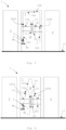
- the transfer device 7 comprises transport means 9 configured to transport the support means 3 along a trajectory 10 which comprises a first section 101, having a vertical component directed upwards (schematically indicated in Figures 3 and 4 with an arrow 1010), and a second section 102, having a vertical component directed downwards (schematically indicated in Figures 3 and 4 with an arrow 1020) .
- the support means 3, and the long-cut pasta 2 supported by them are in contact with the environment external to the system 1, and therefore with the ambient temperature and pressure.
- the transport means 9 are configured in such a way that the support means 3, and the long-cut pasta 2 supported by them, travel the first section 101 in a time comprised between 22 and 50 seconds, preferably as a function of the production size of the system 1.
- the transport means 9 are configured to move the rods 3a along a trajectory 10 perpendicular to the longitudinal axis of said rods 3a, keeping the same parallel to each other.
- the transport means 9 can be transport chains configured so as to transport the rods 3a along the trajectory 10, keeping the same parallel to each other and arranged with their longitudinal axis perpendicular to the trajectory 10.
- the transfer device 7 comprises a frame 8 which supports the transport means 9.
- the trajectory 10 comprises a third section 103, having a component substantially horizontal, which connects the first section 101 and the second section 102 together.
- the first section 101 and the second section 102 are straight and substantially vertical, and the third section 103, which joins them, is substantially straight and substantially horizontal, so that the trajectory 10 has, in a side view, a substantially inverted "U" shape.
- the first section 101 is joined, at one end thereof, directly to the second section 102, so that the trajectory 10 has, in a side view, a substantially inverted "V" shape, preferably with the vertex of the V rounded.
- the transfer device 7 comprises ventilation means 11 positioned in such a way as to send a first air flow 12 (schematically represented in the accompanying figures by arrows), generated by them, towards the long-cut pasta 2 supported by the support means 3 while they travel the first section 101 and/or the second section 102 of the trajectory 10.
- a first air flow 12 (schematically represented in the accompanying figures by arrows), generated by them, towards the long-cut pasta 2 supported by the support means 3 while they travel the first section 101 and/or the second section 102 of the trajectory 10.
- the ventilation means 11 are positioned in such a way that said first air flow 12 hits the first end portion 4a of the long-cut pasta 2 substantially perpendicularly to it.
- the ventilation means 11 are positioned in such a way that said first air flow 12 also hits the second end portion 4b, if present, of the long-cut pasta 2, more preferably substantially perpendicularly to it.
- the ventilation means 11 comprise one or more fans 13, preferably comprising a delivery duct 14 configured to direct a first air flow 12, generated by the one or more fans 13, toward long-cut pasta 2 supported by the support means 3 while they travel the first section 101 and/or the second section 102 of the trajectory.
- the one or more fans 13 comprise an axial flow fan 13a.
- the one or more fans 13 may comprise a tangential flow fan, not represented in the accompanying figures.
- an intermediate region 18 is comprised, and the ventilation means 11 are positioned in said intermediate region 18.
- the length of the trajectory 10 is comprised between 7 and 8 meters.
- the ventilation means 11 are configured to suck a second air flow 19 (schematically illustrated in the accompanying figures by arrows) which passes through long-cut pasta 2 supported by the support means 3 while they travel the first section 101 and/or the second section 102 of the trajectory 10.
- the ventilation means 11 comprise at least one axial flow fan 13a, and the same is arranged in the intermediate region 18, such at least one axial flow fan 13a is configured to generate a first air flow 12, which is directed toward long-cut pasta 2 supported by the support means 3 while they travel the first section 101 of the trajectory 10, and to suck a second air flow 19 which passes through the long-cut pasta 2 supported by the support means 3 while they travel the second section 102 of the trajectory 10.
- the transfer device 7 comprises electronic control means 16 (schematically represented in Figure 1 with a rectangle) operatively connected to the ventilation means 11 and to the transport means 9 in order to control the same;
- the ventilation means 11 are configured in such a way as to be able to vary the flow-rate of the first air flow 12 generated by them, and the electronic control means 16 are advantageously configured for controlling the ventilation means 11 in such a way as to make them deliver a desired air flow-rate (for example comprised between 16,000 and 24,000 m 3 /hour).
- the transport means 9 are configured in such a way as to be able to vary the speed of advance along the trajectory 10 of the support means 3, and the electronic control means 16 are advantageously configured to control the transport means 9 in such a way as to advance the support means 3 at a desired speed along the trajectory 10 (for example comprised between 4 and 9 m/min, preferably as a function of the production size of the system 1).
- the transport means 9 are configured in such a way that the support means 3, and the long-cut pasta 2 supported by them, travel the first section 101 in a time comprised between 20 and 50 seconds, preferably as a function of the production size of the system 1.
- the transport means 9 are configured in such a way that the support means 3, and the long-cut pasta 2 supported by them travel the second section 102 in a time comprised between 20 and 50 seconds, preferably as a function of the production size of the system 1.
- the transport means 9 are configured in such a way that the support means 3, and the long-cut pasta 2 supported by them, travel the entire trajectory 10 in a time comprised between 50 and 120 seconds, advantageously as a function of the production size of the system 1.
- the electronic control means 16 are configured to control the flow-rate of the first air flow 12 and the speed of advance of the support means 3 along the trajectory 10 the one as a function of the other, or independently of each other.
- the ventilation means 11 are configured to generate a first air flow 12 having a temperature and a humidity substantially equal to those of the environment (for example the interior of an industrial warehouse for the production of pasta) in which the transfer device 7 is positioned; for example, in the case where the ventilation means 11 comprise one or more fans 13, these are configured to suck air directly from the environment in which the transfer device 7 is positioned, and to generate the first air flow 12 by moving that air, without changing the temperature or the humidity thereof.
- the ventilation means 11 are configured to generate a first air flow 12 having a temperature and/or a humidity different from those of the environment in which the transfer device 7 is positioned.
- the ventilation means 11 may advantageously comprise conditioning means 15 (schematically illustrated in the accompanying figures by a rectangle), for example a heat exchanger (for example of the air-fluid type), not illustrated, for conditioning the air that passes through the ventilation means 11 and generates the first air flow 12.
- the electronic control means 16 are operatively connected to the conditioning means 15 and configured for controlling them in such a way as to control the temperature of the air that passes through the ventilation means 11 and generates the first air flow 12.
- the latter After having loaded long-cut pasta 2 to be dried onto the support means 3 (for example onto a plurality of rods 3a), the latter are introduced into the drying device 5, from which they come out with a desired value of temperature (advantageously equal to about 80°C) and of humidity; after having come out from the drying device 5, said support means 3, and the long-cut pasta 2 supported by them, pass to the transfer device 7, where the support means 3 are associated with the transport means 9.
- the support means 3, and the long-cut pasta 2 supported by them, are then moved by the transport means 9 along the trajectory 10, travelling first the first section 101, then, if present, the third section 103, and finally the second section 102, until they exit the transfer device 7, from which they then pass into the cooling device 6, in which the long-cut pasta 2 is subjected to the desired cooling, so as to then exit the cooling device 6 itself at a temperature close to ambient temperature (comprised between about 20 and 30 °C).
- the ventilation means 11 In the transfer device 7, while the long-cut pasta 2 passes through the first section 101 and/or the second section 102 of the trajectory 10, the ventilation means 11 generate a first air flow 12, at ambient temperature (therefore between about 20°C and 30°C) or at conditioned temperature (for example lower than ambient temperature) that hits said long-cut pasta 2, reducing the temperature thereof, for example by about 10-15°C.
- the temperature of the long-cut pasta 2 that enters the cooling device 6 is therefore much lower than in the prior art, and preferably equal to or lower than about 65-70°C.
- the use of a system for the treatment of long-cut pasta according to the invention allows to introduce the long-cut pasta inside the cooling device at a significantly lower temperature than known treatment systems for pasta, thus reducing the temperature of the air inside said cooling device, in particular near the inlet region for the pasta.
- a lower inlet temperature in the cooling device allows to reduce the length of the cooling section necessary to bring the temperature of the pasta from the inlet temperature to the ambient temperature, thus allowing to reduce the length, and therefore the overall encumbrance and the related costs, of such cooling device.
- a lower temperature of the pasta entering in the cooling device allows to reduce the energy consumptions necessary to cool the air inside it.
- a lower temperature of the pasta entering the cooling device prevents an undesired evaporation of the humidity contained in the pasta, and an excessive drying thereof in said cooling device.
Landscapes
- Engineering & Computer Science (AREA)
- Mechanical Engineering (AREA)
- General Engineering & Computer Science (AREA)
- Life Sciences & Earth Sciences (AREA)
- Food Science & Technology (AREA)
- Noodles (AREA)
Applications Claiming Priority (1)
| Application Number | Priority Date | Filing Date | Title |
|---|---|---|---|
| IT102022000007514A IT202200007514A1 (it) | 2022-04-14 | 2022-04-14 | Sistema di trattamento per pasta lunga. |
Publications (2)
| Publication Number | Publication Date |
|---|---|
| EP4261485A1 true EP4261485A1 (fr) | 2023-10-18 |
| EP4261485B1 EP4261485B1 (fr) | 2024-06-26 |
Family
ID=82308344
Family Applications (1)
| Application Number | Title | Priority Date | Filing Date |
|---|---|---|---|
| EP23167688.3A Active EP4261485B1 (fr) | 2022-04-14 | 2023-04-13 | Système de traitement pour pâtes alimentaires à coupe longue |
Country Status (3)
| Country | Link |
|---|---|
| EP (1) | EP4261485B1 (fr) |
| BR (1) | BR102023006984A2 (fr) |
| IT (1) | IT202200007514A1 (fr) |
Citations (6)
| Publication number | Priority date | Publication date | Assignee | Title |
|---|---|---|---|---|
| US2583847A (en) * | 1948-11-22 | 1952-01-29 | Buehler Ag Geb | Continuous-type spaghetti drier |
| US2732627A (en) * | 1956-01-31 | Drying apparatus for alimentary paste of | ||
| US3094398A (en) * | 1956-10-24 | 1963-06-18 | Buehler Ag Geb | Apparatus for drying macaroni products |
| FR1457877A (fr) * | 1965-12-03 | 1966-11-04 | Procédé de séchage des pâtes alimentaires et séchoir perfectionné pour la miseen oeuvre de ce procédé | |
| JPS58170445A (ja) * | 1982-04-01 | 1983-10-07 | Hoshino Bussan Kk | 落麺を防止し、活性を持続させ、かつ製造管理が容易なる麺の乾燥方法およびその装置 |
| EP0195394B1 (fr) * | 1985-03-21 | 1991-08-14 | PAVAN MAPIMPIANTI S.p.A. | Dispositif pour le séchage de pâtes alimentaires ou matières similaires |
-
2022
- 2022-04-14 IT IT102022000007514A patent/IT202200007514A1/it unknown
-
2023
- 2023-04-13 EP EP23167688.3A patent/EP4261485B1/fr active Active
- 2023-04-13 BR BR102023006984-3A patent/BR102023006984A2/pt unknown
Patent Citations (6)
| Publication number | Priority date | Publication date | Assignee | Title |
|---|---|---|---|---|
| US2732627A (en) * | 1956-01-31 | Drying apparatus for alimentary paste of | ||
| US2583847A (en) * | 1948-11-22 | 1952-01-29 | Buehler Ag Geb | Continuous-type spaghetti drier |
| US3094398A (en) * | 1956-10-24 | 1963-06-18 | Buehler Ag Geb | Apparatus for drying macaroni products |
| FR1457877A (fr) * | 1965-12-03 | 1966-11-04 | Procédé de séchage des pâtes alimentaires et séchoir perfectionné pour la miseen oeuvre de ce procédé | |
| JPS58170445A (ja) * | 1982-04-01 | 1983-10-07 | Hoshino Bussan Kk | 落麺を防止し、活性を持続させ、かつ製造管理が容易なる麺の乾燥方法およびその装置 |
| EP0195394B1 (fr) * | 1985-03-21 | 1991-08-14 | PAVAN MAPIMPIANTI S.p.A. | Dispositif pour le séchage de pâtes alimentaires ou matières similaires |
Also Published As
| Publication number | Publication date |
|---|---|
| EP4261485B1 (fr) | 2024-06-26 |
| BR102023006984A2 (pt) | 2023-10-24 |
| IT202200007514A1 (it) | 2023-10-14 |
Similar Documents
| Publication | Publication Date | Title |
|---|---|---|
| EP4261485A1 (fr) | Système de traitement pour pâtes alimentaires à coupe longue | |
| CN1572735A (zh) | 加热玻璃的方法和装置 | |
| CN208292866U (zh) | 用于玻璃纤维直接无捻粗纱的拉丝成型装置 | |
| CN110388805A (zh) | 一种烘房结构及烘干方法 | |
| WO2011050169A2 (fr) | Dispositif de séchage pour œufs conditionné à flux laminaire | |
| JP2010267533A (ja) | エナメル線焼付装置 | |
| CN205741574U (zh) | 布料连续染色生产线 | |
| CN106643025B (zh) | 带导流装置的木材干燥室 | |
| CN105177976B (zh) | 一种吹线机 | |
| CN209493477U (zh) | 一种用于调整平板玻璃厚度高点的装置 | |
| CN206760625U (zh) | 泵环连续式果蔬烘干预冷速冻隧道 | |
| WO2011024637A1 (fr) | Appareil et procédé de couchage à nappe | |
| JP6429487B2 (ja) | 乾燥装置、乾燥装置の制御方法、およびその制御装置 | |
| JP7481249B2 (ja) | 熱処理装置 | |
| EP1079011B1 (fr) | Dispositif de séchage à air chaud pour installation d'encollage de fils de chaîne | |
| US11808519B2 (en) | Drying system and method for manufacturing coated metal plate | |
| DE102012007689A1 (de) | Handtuchtrockner | |
| JP5552557B2 (ja) | 給気システムおよび給気方法 | |
| CN110253004B (zh) | 一种铸件用输送冷却装置 | |
| KR101312047B1 (ko) | 냉각탑의 강제히팅에 의한 백연절감장치 | |
| CN221571058U (zh) | 一种粮食烘干塔用调风机构 | |
| JP4036563B2 (ja) | 恒温・恒湿空気供給装置 | |
| JP7481230B2 (ja) | 熱処理装置 | |
| CN106693626A (zh) | 微电脑智能控制干燥器 | |
| CN207674673U (zh) | 一种绞纱烘干车间 |
Legal Events
| Date | Code | Title | Description |
|---|---|---|---|
| PUAI | Public reference made under article 153(3) epc to a published international application that has entered the european phase |
Free format text: ORIGINAL CODE: 0009012 |
|
| STAA | Information on the status of an ep patent application or granted ep patent |
Free format text: STATUS: THE APPLICATION HAS BEEN PUBLISHED |
|
| AK | Designated contracting states |
Kind code of ref document: A1 Designated state(s): AL AT BE BG CH CY CZ DE DK EE ES FI FR GB GR HR HU IE IS IT LI LT LU LV MC ME MK MT NL NO PL PT RO RS SE SI SK SM TR |
|
| STAA | Information on the status of an ep patent application or granted ep patent |
Free format text: STATUS: REQUEST FOR EXAMINATION WAS MADE |
|
| GRAP | Despatch of communication of intention to grant a patent |
Free format text: ORIGINAL CODE: EPIDOSNIGR1 |
|
| STAA | Information on the status of an ep patent application or granted ep patent |
Free format text: STATUS: GRANT OF PATENT IS INTENDED |
|
| 17P | Request for examination filed |
Effective date: 20240119 |
|
| RBV | Designated contracting states (corrected) |
Designated state(s): AL AT BE BG CH CY CZ DE DK EE ES FI FR GB GR HR HU IE IS IT LI LT LU LV MC ME MK MT NL NO PL PT RO RS SE SI SK SM TR |
|
| INTG | Intention to grant announced |
Effective date: 20240227 |
|
| GRAS | Grant fee paid |
Free format text: ORIGINAL CODE: EPIDOSNIGR3 |
|
| GRAA | (expected) grant |
Free format text: ORIGINAL CODE: 0009210 |
|
| STAA | Information on the status of an ep patent application or granted ep patent |
Free format text: STATUS: THE PATENT HAS BEEN GRANTED |
|
| P01 | Opt-out of the competence of the unified patent court (upc) registered |
Effective date: 20240516 |
|
| AK | Designated contracting states |
Kind code of ref document: B1 Designated state(s): AL AT BE BG CH CY CZ DE DK EE ES FI FR GB GR HR HU IE IS IT LI LT LU LV MC ME MK MT NL NO PL PT RO RS SE SI SK SM TR |
|
| REG | Reference to a national code |
Ref country code: GB Ref legal event code: FG4D |
|
| REG | Reference to a national code |
Ref country code: CH Ref legal event code: EP |
|
| REG | Reference to a national code |
Ref country code: DE Ref legal event code: R096 Ref document number: 602023000181 Country of ref document: DE |
|
| PG25 | Lapsed in a contracting state [announced via postgrant information from national office to epo] |
Ref country code: BG Free format text: LAPSE BECAUSE OF FAILURE TO SUBMIT A TRANSLATION OF THE DESCRIPTION OR TO PAY THE FEE WITHIN THE PRESCRIBED TIME-LIMIT Effective date: 20240626 |
|
| PG25 | Lapsed in a contracting state [announced via postgrant information from national office to epo] |
Ref country code: HR Free format text: LAPSE BECAUSE OF FAILURE TO SUBMIT A TRANSLATION OF THE DESCRIPTION OR TO PAY THE FEE WITHIN THE PRESCRIBED TIME-LIMIT Effective date: 20240626 Ref country code: FI Free format text: LAPSE BECAUSE OF FAILURE TO SUBMIT A TRANSLATION OF THE DESCRIPTION OR TO PAY THE FEE WITHIN THE PRESCRIBED TIME-LIMIT Effective date: 20240626 |
|
| REG | Reference to a national code |
Ref country code: LT Ref legal event code: MG9D |
|
| PG25 | Lapsed in a contracting state [announced via postgrant information from national office to epo] |
Ref country code: GR Free format text: LAPSE BECAUSE OF FAILURE TO SUBMIT A TRANSLATION OF THE DESCRIPTION OR TO PAY THE FEE WITHIN THE PRESCRIBED TIME-LIMIT Effective date: 20240927 |
|
| PG25 | Lapsed in a contracting state [announced via postgrant information from national office to epo] |
Ref country code: LV Free format text: LAPSE BECAUSE OF FAILURE TO SUBMIT A TRANSLATION OF THE DESCRIPTION OR TO PAY THE FEE WITHIN THE PRESCRIBED TIME-LIMIT Effective date: 20240626 |
|
| REG | Reference to a national code |
Ref country code: NL Ref legal event code: MP Effective date: 20240626 |
|
| PG25 | Lapsed in a contracting state [announced via postgrant information from national office to epo] |
Ref country code: NO Free format text: LAPSE BECAUSE OF FAILURE TO SUBMIT A TRANSLATION OF THE DESCRIPTION OR TO PAY THE FEE WITHIN THE PRESCRIBED TIME-LIMIT Effective date: 20240926 Ref country code: LV Free format text: LAPSE BECAUSE OF FAILURE TO SUBMIT A TRANSLATION OF THE DESCRIPTION OR TO PAY THE FEE WITHIN THE PRESCRIBED TIME-LIMIT Effective date: 20240626 Ref country code: HR Free format text: LAPSE BECAUSE OF FAILURE TO SUBMIT A TRANSLATION OF THE DESCRIPTION OR TO PAY THE FEE WITHIN THE PRESCRIBED TIME-LIMIT Effective date: 20240626 Ref country code: GR Free format text: LAPSE BECAUSE OF FAILURE TO SUBMIT A TRANSLATION OF THE DESCRIPTION OR TO PAY THE FEE WITHIN THE PRESCRIBED TIME-LIMIT Effective date: 20240927 Ref country code: FI Free format text: LAPSE BECAUSE OF FAILURE TO SUBMIT A TRANSLATION OF THE DESCRIPTION OR TO PAY THE FEE WITHIN THE PRESCRIBED TIME-LIMIT Effective date: 20240626 Ref country code: BG Free format text: LAPSE BECAUSE OF FAILURE TO SUBMIT A TRANSLATION OF THE DESCRIPTION OR TO PAY THE FEE WITHIN THE PRESCRIBED TIME-LIMIT Effective date: 20240626 Ref country code: RS Free format text: LAPSE BECAUSE OF FAILURE TO SUBMIT A TRANSLATION OF THE DESCRIPTION OR TO PAY THE FEE WITHIN THE PRESCRIBED TIME-LIMIT Effective date: 20240926 |
|
| PG25 | Lapsed in a contracting state [announced via postgrant information from national office to epo] |
Ref country code: NL Free format text: LAPSE BECAUSE OF FAILURE TO SUBMIT A TRANSLATION OF THE DESCRIPTION OR TO PAY THE FEE WITHIN THE PRESCRIBED TIME-LIMIT Effective date: 20240626 |
|
| REG | Reference to a national code |
Ref country code: AT Ref legal event code: MK05 Ref document number: 1698027 Country of ref document: AT Kind code of ref document: T Effective date: 20240626 |
|
| PG25 | Lapsed in a contracting state [announced via postgrant information from national office to epo] |
Ref country code: NL Free format text: LAPSE BECAUSE OF FAILURE TO SUBMIT A TRANSLATION OF THE DESCRIPTION OR TO PAY THE FEE WITHIN THE PRESCRIBED TIME-LIMIT Effective date: 20240626 |
|
| PG25 | Lapsed in a contracting state [announced via postgrant information from national office to epo] |
Ref country code: PT Free format text: LAPSE BECAUSE OF FAILURE TO SUBMIT A TRANSLATION OF THE DESCRIPTION OR TO PAY THE FEE WITHIN THE PRESCRIBED TIME-LIMIT Effective date: 20241028 |
|
| PG25 | Lapsed in a contracting state [announced via postgrant information from national office to epo] |
Ref country code: PT Free format text: LAPSE BECAUSE OF FAILURE TO SUBMIT A TRANSLATION OF THE DESCRIPTION OR TO PAY THE FEE WITHIN THE PRESCRIBED TIME-LIMIT Effective date: 20241028 |
|
| PG25 | Lapsed in a contracting state [announced via postgrant information from national office to epo] |
Ref country code: PL Free format text: LAPSE BECAUSE OF FAILURE TO SUBMIT A TRANSLATION OF THE DESCRIPTION OR TO PAY THE FEE WITHIN THE PRESCRIBED TIME-LIMIT Effective date: 20240626 |
|
| PG25 | Lapsed in a contracting state [announced via postgrant information from national office to epo] |
Ref country code: EE Free format text: LAPSE BECAUSE OF FAILURE TO SUBMIT A TRANSLATION OF THE DESCRIPTION OR TO PAY THE FEE WITHIN THE PRESCRIBED TIME-LIMIT Effective date: 20240626 |
|
| PG25 | Lapsed in a contracting state [announced via postgrant information from national office to epo] |
Ref country code: IS Free format text: LAPSE BECAUSE OF FAILURE TO SUBMIT A TRANSLATION OF THE DESCRIPTION OR TO PAY THE FEE WITHIN THE PRESCRIBED TIME-LIMIT Effective date: 20241026 Ref country code: AT Free format text: LAPSE BECAUSE OF FAILURE TO SUBMIT A TRANSLATION OF THE DESCRIPTION OR TO PAY THE FEE WITHIN THE PRESCRIBED TIME-LIMIT Effective date: 20240626 |
|
| PG25 | Lapsed in a contracting state [announced via postgrant information from national office to epo] |
Ref country code: CZ Free format text: LAPSE BECAUSE OF FAILURE TO SUBMIT A TRANSLATION OF THE DESCRIPTION OR TO PAY THE FEE WITHIN THE PRESCRIBED TIME-LIMIT Effective date: 20240626 |
|
| PG25 | Lapsed in a contracting state [announced via postgrant information from national office to epo] |
Ref country code: SK Free format text: LAPSE BECAUSE OF FAILURE TO SUBMIT A TRANSLATION OF THE DESCRIPTION OR TO PAY THE FEE WITHIN THE PRESCRIBED TIME-LIMIT Effective date: 20240626 Ref country code: RO Free format text: LAPSE BECAUSE OF FAILURE TO SUBMIT A TRANSLATION OF THE DESCRIPTION OR TO PAY THE FEE WITHIN THE PRESCRIBED TIME-LIMIT Effective date: 20240626 |
|
| PG25 | Lapsed in a contracting state [announced via postgrant information from national office to epo] |
Ref country code: ES Free format text: LAPSE BECAUSE OF FAILURE TO SUBMIT A TRANSLATION OF THE DESCRIPTION OR TO PAY THE FEE WITHIN THE PRESCRIBED TIME-LIMIT Effective date: 20240626 Ref country code: SM Free format text: LAPSE BECAUSE OF FAILURE TO SUBMIT A TRANSLATION OF THE DESCRIPTION OR TO PAY THE FEE WITHIN THE PRESCRIBED TIME-LIMIT Effective date: 20240626 |
|
| PG25 | Lapsed in a contracting state [announced via postgrant information from national office to epo] |
Ref country code: SM Free format text: LAPSE BECAUSE OF FAILURE TO SUBMIT A TRANSLATION OF THE DESCRIPTION OR TO PAY THE FEE WITHIN THE PRESCRIBED TIME-LIMIT Effective date: 20240626 Ref country code: SK Free format text: LAPSE BECAUSE OF FAILURE TO SUBMIT A TRANSLATION OF THE DESCRIPTION OR TO PAY THE FEE WITHIN THE PRESCRIBED TIME-LIMIT Effective date: 20240626 Ref country code: RO Free format text: LAPSE BECAUSE OF FAILURE TO SUBMIT A TRANSLATION OF THE DESCRIPTION OR TO PAY THE FEE WITHIN THE PRESCRIBED TIME-LIMIT Effective date: 20240626 Ref country code: PL Free format text: LAPSE BECAUSE OF FAILURE TO SUBMIT A TRANSLATION OF THE DESCRIPTION OR TO PAY THE FEE WITHIN THE PRESCRIBED TIME-LIMIT Effective date: 20240626 Ref country code: IS Free format text: LAPSE BECAUSE OF FAILURE TO SUBMIT A TRANSLATION OF THE DESCRIPTION OR TO PAY THE FEE WITHIN THE PRESCRIBED TIME-LIMIT Effective date: 20241026 Ref country code: ES Free format text: LAPSE BECAUSE OF FAILURE TO SUBMIT A TRANSLATION OF THE DESCRIPTION OR TO PAY THE FEE WITHIN THE PRESCRIBED TIME-LIMIT Effective date: 20240626 Ref country code: EE Free format text: LAPSE BECAUSE OF FAILURE TO SUBMIT A TRANSLATION OF THE DESCRIPTION OR TO PAY THE FEE WITHIN THE PRESCRIBED TIME-LIMIT Effective date: 20240626 Ref country code: CZ Free format text: LAPSE BECAUSE OF FAILURE TO SUBMIT A TRANSLATION OF THE DESCRIPTION OR TO PAY THE FEE WITHIN THE PRESCRIBED TIME-LIMIT Effective date: 20240626 Ref country code: AT Free format text: LAPSE BECAUSE OF FAILURE TO SUBMIT A TRANSLATION OF THE DESCRIPTION OR TO PAY THE FEE WITHIN THE PRESCRIBED TIME-LIMIT Effective date: 20240626 |
|
| REG | Reference to a national code |
Ref country code: DE Ref legal event code: R097 Ref document number: 602023000181 Country of ref document: DE |
|
| PG25 | Lapsed in a contracting state [announced via postgrant information from national office to epo] |
Ref country code: DK Free format text: LAPSE BECAUSE OF FAILURE TO SUBMIT A TRANSLATION OF THE DESCRIPTION OR TO PAY THE FEE WITHIN THE PRESCRIBED TIME-LIMIT Effective date: 20240626 |
|
| PGFP | Annual fee paid to national office [announced via postgrant information from national office to epo] |
Ref country code: TR Payment date: 20250327 Year of fee payment: 3 |
|
| PLBE | No opposition filed within time limit |
Free format text: ORIGINAL CODE: 0009261 |
|
| STAA | Information on the status of an ep patent application or granted ep patent |
Free format text: STATUS: NO OPPOSITION FILED WITHIN TIME LIMIT |
|
| 26N | No opposition filed |
Effective date: 20250327 |
|
| PGFP | Annual fee paid to national office [announced via postgrant information from national office to epo] |
Ref country code: DE Payment date: 20250305 Year of fee payment: 3 |
|
| PGFP | Annual fee paid to national office [announced via postgrant information from national office to epo] |
Ref country code: IT Payment date: 20250430 Year of fee payment: 3 |
|
| PG25 | Lapsed in a contracting state [announced via postgrant information from national office to epo] |
Ref country code: SE Free format text: LAPSE BECAUSE OF FAILURE TO SUBMIT A TRANSLATION OF THE DESCRIPTION OR TO PAY THE FEE WITHIN THE PRESCRIBED TIME-LIMIT Effective date: 20240626 |
|
| PG25 | Lapsed in a contracting state [announced via postgrant information from national office to epo] |
Ref country code: LU Free format text: LAPSE BECAUSE OF NON-PAYMENT OF DUE FEES Effective date: 20250413 |
|
| PG25 | Lapsed in a contracting state [announced via postgrant information from national office to epo] |
Ref country code: MC Free format text: LAPSE BECAUSE OF FAILURE TO SUBMIT A TRANSLATION OF THE DESCRIPTION OR TO PAY THE FEE WITHIN THE PRESCRIBED TIME-LIMIT Effective date: 20240626 |
|
| REG | Reference to a national code |
Ref country code: BE Ref legal event code: MM Effective date: 20250430 |
|
| PG25 | Lapsed in a contracting state [announced via postgrant information from national office to epo] |
Ref country code: BE Free format text: LAPSE BECAUSE OF NON-PAYMENT OF DUE FEES Effective date: 20250430 |
|
| PG25 | Lapsed in a contracting state [announced via postgrant information from national office to epo] |
Ref country code: IE Free format text: LAPSE BECAUSE OF NON-PAYMENT OF DUE FEES Effective date: 20250413 |
|
| PGFP | Annual fee paid to national office [announced via postgrant information from national office to epo] |
Ref country code: FR Payment date: 20260309 Year of fee payment: 4 |