EP4261548B1 - Kalibriermethode, kalibrierinstallation und methode zur montage eines stromsensors für schaltanlagen, zugehöriger stromsensor - Google Patents
Kalibriermethode, kalibrierinstallation und methode zur montage eines stromsensors für schaltanlagen, zugehöriger stromsensor Download PDFInfo
- Publication number
- EP4261548B1 EP4261548B1 EP23166770.0A EP23166770A EP4261548B1 EP 4261548 B1 EP4261548 B1 EP 4261548B1 EP 23166770 A EP23166770 A EP 23166770A EP 4261548 B1 EP4261548 B1 EP 4261548B1
- Authority
- EP
- European Patent Office
- Prior art keywords
- rogowski coil
- magnetic circuit
- current transformer
- current sensor
- casing
- Prior art date
- Legal status (The legal status is an assumption and is not a legal conclusion. Google has not performed a legal analysis and makes no representation as to the accuracy of the status listed.)
- Active
Links
Images


Classifications
-
- G—PHYSICS
- G01—MEASURING; TESTING
- G01R—MEASURING ELECTRIC VARIABLES; MEASURING MAGNETIC VARIABLES
- G01R35/00—Testing or calibrating of apparatus covered by the other groups of this subclass
- G01R35/005—Calibrating; Standards or reference devices, e.g. voltage or resistance standards, "golden" references
-
- G—PHYSICS
- G01—MEASURING; TESTING
- G01R—MEASURING ELECTRIC VARIABLES; MEASURING MAGNETIC VARIABLES
- G01R15/00—Details of measuring arrangements of the types provided for in groups G01R17/00 - G01R29/00, G01R33/00 - G01R33/26 or G01R35/00
- G01R15/14—Adaptations providing voltage or current isolation, e.g. for high-voltage or high-current networks
- G01R15/18—Adaptations providing voltage or current isolation, e.g. for high-voltage or high-current networks using inductive devices, e.g. transformers
- G01R15/181—Adaptations providing voltage or current isolation, e.g. for high-voltage or high-current networks using inductive devices, e.g. transformers using coils without a magnetic core, e.g. Rogowski coils
-
- G—PHYSICS
- G01—MEASURING; TESTING
- G01R—MEASURING ELECTRIC VARIABLES; MEASURING MAGNETIC VARIABLES
- G01R35/00—Testing or calibrating of apparatus covered by the other groups of this subclass
- G01R35/02—Testing or calibrating of apparatus covered by the other groups of this subclass of auxiliary devices, e.g. of instrument transformers according to prescribed transformation ratio, phase angle, or wattage rating
Definitions
- the present invention relates to the field of methods for calibrating a current sensor for electrical cut-off apparatus, the field of installations for calibrating a current sensor for electrical cut-off apparatus, the field of methods for assembling a current sensor for electrical cut-off apparatus and the field of current sensors for electrical cut-off apparatus.
- the invention relates to electrical cut-off devices in the tertiary sector, such as, for example, air circuit breakers usually designated by the acronym ACB or molded case circuit breakers.
- the current measurement in such circuit breakers is carried out by the current sensor subassembly which is made up of two parts.
- the first part is a Rogowski coil which is used to measure the current.
- the second part is a current transformer which is used, if necessary, to supply the electronic elements of the electrical cut-off apparatus, for example an air circuit breaker.
- the sensitivity of the Rogowski coil can vary from one Rogowski coil to another, in particular due to the non-repeatability of the manufacturing of the Rogowski coil.
- the plastic part forming the support on which the wire of the Rogowski coil is wound and the wire of the Rogowski coil can have tiny variations in dimensions.
- the circuit breaker that integrates the current sensor has a current path that is not uniform.
- the variations in sensitivity of the Rogowski coil affect the measurement of the current due to the non-uniformity of the current path, which is not desirable.
- the current path has, for example, a U shape, which creates a non-uniform magnetic field and causes the sensitivity of the Rogowski coil to vary. depending on its positioning relative to the current path due to the lack of control of dimensional variations.
- CN 106 645 861 A And CN 104 764 928 A disclose the calibration of a Rogowski current sensor.
- the present invention aims to overcome at least one of these drawbacks and also to propose a solution making it possible to limit the influence of the non-repeatability of manufacturing of the Rogowski coil on the current measurement.
- the invention relates to a method for calibrating a current sensor for an electrical cut-off device, said current sensor comprising at least one current transformer and a Rogowski coil with an axis of rotation, the current transformer comprising at least one magnetic circuit on which the Rogowski coil is capable of being superimposed so as to be capable of being crossed by a conductor,
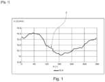
- a step of measuring the sensitivity of the Rogowski coil during which a current is applied to said conductor so as to generate a non-uniform magnetic field and a voltage measurement at the output of the Rogowski coil is carried out as a function of the position of the Rogowski coil relative to the position of the magnetic circuit around the axis of rotation,
- a Rogowski coil position selection step wherein a so-called selected position of the Rogowski coil relative to said position of the magnetic circuit about the axis of rotation is selected based on the sensitivity measurements made during said Rogowski coil sensitivity measurement step, such that at the so-called selected position, the sensitivity is equal to a predetermined target sensitivity.
- the invention also relates to an installation for calibrating a current sensor for electrical cut-off equipment, said current sensor comprising at least one current transformer or a reference current transformer and a Rogowski coil with an axis of rotation, the current transformer comprising at least one magnetic circuit or the reference current transformer comprising at least one reference magnetic circuit, said one magnetic circuit or reference magnetic circuit on which the Rogowski coil is capable of being superimposed so as to be capable of being crossed by a conductor, and for the implementation of the calibration method according to the invention,
- a rotating element arranged to rotate at least the Rogowski coil or at least the magnetic circuit or the reference magnetic circuit about the axis of rotation
- a blocking element arranged to block rotation about the axis of rotation of the Rogowski coil or the magnetic circuit or the reference magnetic circuit respectively when rotating the magnetic circuit or the reference magnetic circuit or when rotating the Rogowski coil by said element.
- the invention also relates to a current sensor for an electrical cut-off device, said current sensor comprising at least one current transformer and a Rogowski coil with an axis of rotation, the current transformer comprising at least one magnetic circuit on which the Rogowski coil is capable of being superimposed so as to be capable of being crossed by a conductor,
- said current sensor is characterized in that it comprises immobilization means arranged to immobilize the so-called selected position of the Rogowski coil relative to said position of the magnetic circuit, which being selected at the end of said step of selecting the position of the Rogowski coil of the method of calibrating a current sensor for electrical cut-off equipment according to the invention.
- the invention also relates to a method of assembling a current sensor according to the invention, comprising at least one housing comprising a first shell and a second shell, the first shell having a first receiving zone of a shape complementary to that at least of the Rogowski coil receiving the Rogowski coil and the second shell having a second receiving zone of a shape complementary to that at least of the current transformer receiving said current transformer, said assembly method is characterized in that it comprises at least:
- a third step of assembling a second shell during which the second shell is assembled to the first shell so as to assemble the housing containing the calibrated subassembly and the current transformer.
- the invention relates to a method for calibrating a current sensor 1 for an electrical cut-off device, said current sensor 1 comprising at least one current transformer 2 and a Rogowski coil 3 with an axis of rotation A1, the current transformer 2 comprising at least one magnetic circuit 4 on which the Rogowski coil 3 is capable of being superimposed so as to be capable of being crossed by a conductor L.
- the calibration method according to the invention makes it possible to angularly position the Rogowski coil 3 relative to the current transformer 2 in a position, called the so-called selected position PS for which the sensitivity is equal to a predetermined target sensitivity.
- this predetermined target sensitivity corresponds to the sensitivity of an ideal theoretical coil.
- the conductor L has a U shape as illustrated in figure 11 .
- the conductor L does not have a linear or bar shape.
- said step of measuring the sensitivity of the Rogowski coil 3 makes it possible to obtain a curve Z of the voltage U at the output of the Rogowski coil 3 as a function of the position P of the Rogowski coil 3 at a current I.
- the method for calibrating a current sensor 1 for an electrical cut-off device may further comprise a step of immobilizing the so-called selected position PS of the Rogowski coil 3, during which the so-called selected position PS of the Rogowski coil 3, which being selected at the end of said step of selecting the position P of the Rogowski coil 3, is immobilized by immobilization means 5 relative to said position of the magnetic circuit 4.
- the immobilization step makes it possible to freeze the so-called selected position PS of the Rogowski coil 3 with respect to the current transformer 2.
- This immobilization by the immobilization means can be direct or indirect.
- the immobilization means 5 may comprise, alone or in combination, bonding means, such as glue or double-sided adhesive, other equivalent means of fixing or assembly may be envisaged, in particular using additional parts, means of locating or marking the so-called selected position PS, such as a marker or a symbol.
- the Rogowski coil 3 is rotated about the axis of rotation A1 by a rotating element relative to the magnetic circuit 4 of the current transformer 2 or to a reference magnetic circuit of a reference current transformer which is fixed or the magnetic circuit 4 or the reference magnetic circuit is rotated about the axis of rotation A1 by said rotating element relative to the Rogowski coil 3 which is fixed.
- reference current transformer (not shown) is understood to mean a current transformer comprising a reference magnetic circuit (not shown) which is specifically dedicated to the calibration method according to the invention.
- the reference current transformer differs from the current transformer 2 which is part of the current sensor 1 according to the invention.
- the measurement of voltage U at the output of the Rogowski coil 3 and the rotation around the axis of rotation A1 of the Rogowski coil 3 or of the magnetic circuit 4 or of the reference magnetic circuit are carried out simultaneously.
- this simultaneity makes it possible to make the solution industrializable, since it is possible to achieve a cycle time making it possible to implement the calibration method according to the invention on the entire set of current sensors 1 to be calibrated.
- the U voltage measurement can be performed at the same time as the rotation.
- the U voltage measurement can be performed at one or more static positions, in which case the rotation is performed in the absence of U voltage measurement, then when a desired position is reached the U voltage measurement is performed at this desired position without rotation and so on.
- said step of measuring the sensitivity of the Rogowski coil 3 is carried out for angular positions P of the Rogowski coil 3 relative to a reference position of the magnetic circuit 4 which are between 0 degrees and 360 degrees.
- the invention also relates to an installation for calibrating a current sensor 1 for an electrical cut-off device, said current sensor 1 comprising at least one current transformer 2 or a reference current transformer and a Rogowski coil 3 with an axis of rotation A1, the current transformer 2 comprising at least one magnetic circuit 4 or the reference current transformer comprising at least one reference magnetic circuit, said magnetic circuit 4 or said reference magnetic circuit on which the Rogowski coil 3 is capable of being superimposed so as to be capable of being crossed by a conductor L, and for implementing the calibration method according to the invention.
- said rotating element is a rotation plate.
- Said rotating element may comprise for example a motor (not shown) and a support whose shape makes it possible to receive and/or matches the shape of the Rogowski coil 3 or that of the magnetic circuit 4 or that of the reference magnetic circuit.
- said locking element 7 consists of means for exerting a pressing force on the Rogowski coil 3 preferably in a direction substantially perpendicular to the axis of rotation A1.
- the locking element may be a clamp or a clamping means or the like.
- the invention also relates to a current sensor 1 as illustrated in particular by the figures 2 And 6 to 11 .
- Said current sensor 1 comprises at least the current transformer 2 and the Rogowski coil 3 with rotation axis A1.
- the current transformer 2 comprises at least the magnetic circuit 4 on which the Rogowski coil 3 is capable of being superimposed so as to be capable of being crossed by a conductor L.
- said current sensor 1 is characterized in that it comprises immobilization means 5 arranged to immobilize the so-called selected position PS of the Rogowski coil 3 relative to said position of the magnetic circuit 4, which being selected at the end of said step of selecting the position P of the Rogowski coil 3 of the method of calibrating a current sensor 1 for an electrical cut-off device according to the invention and as described above.
- the immobilization means 5 make it possible to identify and/or freeze the so-called selected position PS of the Rogowski coil 3 relative to said position of the magnetic circuit 4.
- These immobilization means 5 may comprise bonding means, such as glue or double-sided adhesive, other equivalent fixing or assembly means may be envisaged, in particular using additional parts.
- the Rogowski coil 3 consists of a non-magnetic torus around which a wire is wound.
- the current sensor 1 comprises bonding means or equivalent fixing or assembly means located between said magnetic circuit 4 and the Rogowski coil 3, to fix the Rogowski coil 3 according to the so-called selected position PS on the magnetic circuit 4 of the current transformer 2.
- the immobilization means 5 comprise at least the gluing means or the equivalent means of fixing or assembly and the immobilization is direct.
- the Rogowski coil 3 is glued or fixed or assembled on the magnetic circuit 4 according to the so-called selected position PS.
- the current sensor 1 comprises a housing comprising a first shell and a second shell, the first shell having a first receiving zone of shape complementary to that at least of the Rogowski coil 3 receiving the Rogowski coil 3 and the second shell having a second receiving zone of shape complementary to that at least of the current transformer 2 receiving said current transformer 2 and comprises bonding means or equivalent fixing or assembly means located between the Rogowski coil 3 and the second shell, for fixing the Rogowski coil 3 according to the so-called selected position PS relative to the magnetic circuit 4 of the current transformer 2.
- the immobilization means 5 comprise at least the bonding means or the equivalent means of fixing or assembly and the immobilization is indirect, since it is carried out by means of the second shell of the housing.
- the Rogowski coil 3 is superimposed directly on the magnetic circuit 4 according to the so-called selected position PS and is glued or fixed or assembled to the second shell.
- the current sensor 1 comprises a housing comprising a first shell and a second shell, the first shell having a first receiving zone of shape complementary to that at least of the Rogowski coil 3 receiving the Rogowski coil and the second shell having a second receiving zone of shape complementary to that at least of the current transformer 2 receiving said current transformer 2 and comprises bonding means or equivalent fixing or assembly means located between the Rogowski coil 3 and the first shell, for fixing the Rogowski coil 3 according to the so-called selected position PS relative to the magnetic circuit 4 of the current transformer 2.
- the immobilization means 5 comprise at least the bonding means or the equivalent means of fixing or assembly and the immobilization is indirect, since it is carried out by means of the first shell of the housing.
- the Rogowski coil 3 is superimposed directly on the magnetic circuit 4 according to the so-called selected position PS and is glued or fixed or assembled to the first shell.
- the current sensor 1 comprises an intermediate element 8, arranged to be disposed between said magnetic circuit 4 and the Rogowski coil 3, on which the Rogowski coil 3 is fixed according to the so-called selected position PS by fixing means 9 and said intermediate element 8 comprises at least one foolproofing member 10 for assembly at least with said magnetic circuit 4 of the current transformer 2 and/or with the first shell 12, said intermediate element 8 fixed to the Rogowski coil 3 forming a calibrated subassembly 11.
- the immobilization means 5 comprise at least said intermediate element 8 and the fixing means 9 and the immobilization is indirect, since it is carried out by means of the intermediate element 8.
- the intermediate element 8 is interposed between the Rogowski coil 3 and the magnetic circuit 4.
- the Rogowski coil 3 is therefore superimposed directly on the intermediate element 8 according to the so-called selected position PS and is glued or fixed or assembled thereon.
- Said at least one foolproofing member 10, 21 makes it possible to assemble the intermediate element 8 with said magnetic circuit 4 so that the Rogowski coil 3 is arranged relative to said position of the magnetic circuit 4 in the so-called selected position PS.
- Said intermediate element 8 may be in the form of a flat part provided with an annular portion 18 comprising a receiving face 19 which has dimensions and a shape allowing it to receive the Rogowski coil 3, as illustrated in figure 5 .
- Said intermediate element 8 is preferably made of cardboard or equivalent.
- the Rogowski coil 3 is preferably glued or fixed or assembled on the receiving face 19 by the fixing means 9.
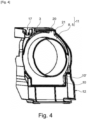
- the current sensor 1 may comprise a housing 14 which contains at least the current transformer 2 and the Rogowski coil 3.
- This housing 14 contains the intermediate element 8.
- the housing 14 comprises a first shell 12 and a second shell 13.
- the first shell 12 preferably has a first receiving zone 15 of a shape complementary to that of at least the Rogowski coil 3 and the current transformer 2.
- the second shell 13 preferably has a second receiving zone (not visible) of a shape complementary to that at least of the current transformer 2.
- the first shell 12 and the second shell 13 are made of plastic.
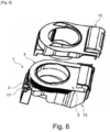
- Said intermediate element 8 comprises at least one foolproofing member 10, 20 which is provided in particular to cooperate with a complementary portion 21, 10' of the first receiving zone 15 of the first shell 12 in order to facilitate the positioning of the calibrated subassembly 11 in the first shell 12.
- a foolproofing member 10, 21 may comprise at least one tab that is inserted into a complementary portion 21, 10' of the first receiving zone 15 of the first shell 12.
- the intermediate element 8 comprises three tabs.
- the foolproofing member may comprise at least one hole that is inserted into a projecting stud of the first receiving zone 15.
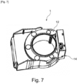
- the first shell 12 preferably comprises a connection zone 17 for the output of the two wires of the Rogowski coil 3.
- the two wires of the Rogowski coil 3 are twisted to immunize the Rogowski coil 3 to electrical and/or magnetic disturbances.
- the length of wires preferably has a sufficient length to allow positioning at the opposite extreme, i.e. 180 degrees, from the connection zone 17.
- this configuration allows the output of the two wires of the Rogowski coil 3 to be found in all possible positions P of the Rogowski coil 3 and preferably between 0 degrees and 360 degrees.
- the Rogowski coil 3 is polarized. This polarity is determined by the winding process of the Rogowski coil 3. One of the two wires is shorter so as not to lose this polarity information.
- the invention also relates to an electrical cut-off device comprising at least one current sensor 1 according to the invention.
- said electrical cut-off device is a circuit breaker, for example of the air circuit breaker or ACB (Air Circuit Breaker) type or an MCCB (Molded Case Circuit Breaker).
- ACB Air Circuit Breaker
- MCCB Molded Case Circuit Breaker
- the Rogowski coil 3 of the current sensor 1 is used to measure the current of a current path (not shown) included in the electrical cut-off device.
- this current path has a U shape and is not linear or bar-shaped.
- the current transformer 2 of the current sensor can, for example, supply power to an electronic unit (not shown) included in the electrical cut-off device.
- the assembly method comprises a step of orienting the output of the two wires of the Rogowski coil 3, which is carried out between the first step and the second step, during which the output of the two wires of the Rogowski coil 3 is oriented opposite the connection zone 17.
- the Rogowski coil 3 being polarized, during the orientation step, the surplus of one of the two wires is not cut to preserve the information on the polarity.
- the calibration method according to the invention is first implemented, then the assembly method is implemented.
- the current sensor 1 according to the invention is advantageously obtained, represented in particular in Figures 6 to 11 .
- the current transformer 2, the intermediate element 8 and the Rogowski coil 3 are made available and placed on an installation according to the invention.
- the Rogowski coil 3 is immobilized by the blocking element 7 of this installation, while the magnetic circuit 4 of the current transformer 2 is arranged on the rotating element of this installation.
- the intermediate element 8 is preferably assembled with said magnetic circuit 4 of the current transformer 2 by assembly means or placed on said magnetic circuit 4 of the current transformer 2 preferably using said at least one foolproofing member 10, 21.
- a second step said step of measuring the sensitivity of the Rogowski coil 3 is carried out.
- the magnetic circuit 4 is rotated about the axis of rotation A1 by said rotating element relative to the Rogowski coil 3 which is fixed and the measurement of voltage U at the output of the Rogowski coil 3 is carried out.
- a third step the step of selecting the position P of the Rogowski coil 3 is carried out, which makes it possible to obtain the value of the so-called selected position PS.
- the step of immobilizing the so-called selected position PS of the Rogowski coil 3 is implemented during which the so-called selected position PS of the Rogowski coil 3 is immobilized by immobilization means 5 relative to said position of the magnetic circuit 4.
- the Rogowski coil 3 can be fixed on the intermediate element 8 according to the so-called selected position PS by fixing means 9, which can consist of bonding means, such as glue or a double-sided adhesive, other equivalent means may be envisaged, for example assembly means.
- the intermediate element 8 is thus arranged between said magnetic circuit 4 and the Rogowski coil 3.
- a calibrated subassembly 11 is advantageously obtained comprising said intermediate element 8 fixed to the Rogowski coil 3.
- the calibrated subassembly 11 is arranged in the first shell 12 which has a first receiving zone 15 of a shape complementary to that of the calibrated subassembly 11. Said at least one foolproofing member 10, 20 and the complementary portion 10', 21 of the first receiving zone 15 are assembled to facilitate positioning in the first shell 12.
- Fastening means 22 such as bonding means, for example glue or double-sided adhesive or other equivalent means can be envisaged, are preferably used between the first receiving zone 15 of the first shell 12 and a face 16 of the Rogowski coil opposite a face 16' on which the intermediate element 8 is fixed to hold the calibrated subassembly 11 in the first shell 12, as can be seen in the figure. figure 10 .
- the second step of assembly of the current transformer 2 is carried out.
- the Rogowski coil 3 is immobilized in the so-called selected position PS with respect to the current transformer 2.
- the third step of assembling a second shell 13 is carried out to close the housing 14 using the second shell 13.
Landscapes
- Physics & Mathematics (AREA)
- General Physics & Mathematics (AREA)
- Engineering & Computer Science (AREA)
- Power Engineering (AREA)
- Measuring Instrument Details And Bridges, And Automatic Balancing Devices (AREA)
Claims (12)
- Verfahren zur Kalibrierung eines Stromsensors (1) für ein elektrisches Abschaltgerät, wobei der Stromsensor (1) mindestens einen Stromwandler (2) und eine Rogowskispule (3) mit einer Drehachse (A1) enthält, wobei der Stromwandler (2) mindestens einen Magnetkreis (4) enthält, auf den die Rogowskispule (3) überlagert werden kann, um von einem Leiter (L) durchquert werden zu können,
wobei das Kalibrierungsverfahren dadurch gekennzeichnet ist, dass es mindestens enthält:- einen Schritt der Messung der Empfindlichkeit der Rogowskispule (3), in dem ein Strom (I) an den Leiter (L) angelegt wird, um ein ungleichförmiges Magnetfeld zu erzeugen, und eine Spannungsmessung am Ausgang der Rogowskispule (3) abhängig von der Position (P) der Rogowskispule (3) bezüglich der Position des Magnetkreises (4) um die Drehachse (A1) herum ausgeführt wird,- einen Schritt der Auswahl der Position (P) der Rogowskispule (3), in dem eine so genannte ausgewählte Position (PS) der Rogowskispule (3) bezüglich der Position des Magnetkreises (4) um die Drehachse (A1) abhängig von den Empfindlichkeitsmessungen ausgewählt wird, die im Schritt der Messung der Empfindlichkeit der Rogowskispule (3) durchgeführt werden, so dass in der so genannten ausgewählten Position (PS) die Empfindlichkeit gleich einer vorbestimmten Ziel-Empfindlichkeit ist. - Kalibrierungsverfahren eines Stromsensors (1) für ein elektrisches Abschaltgerät nach Anspruch 1, dadurch gekennzeichnet, dass es außerdem einen Schritt der Immobilisierung der so genannten ausgewählten Position (PS) der Rogowskispule (3) enthält, in dem die so genannte ausgewählte Position (PS) der Rogowskispule (3), die am Ende des Auswahlschritts der Position (P) der Rogowskispule (3) ausgewählt wird, durch Immobilisierungseinrichtungen (5) bezüglich der Position des Magnetkreises (4) immobilisiert wird.
- Kalibrierungsverfahren eines Stromsensors (1) für ein elektrisches Abschaltgerät nach einem der Ansprüche 1 bis 2, dadurch gekennzeichnet, dass im Messschritt der Empfindlichkeit der Rogowskispule (3) die Rogowskispule (3) durch ein drehbares Element bezüglich des Magnetkreises (4) des Stromwandlers (2) oder eines Bezugs-Magnetkreises eines Bezugs-Stromwandlers, der ortsfest ist, um die Drehachse (A1) in Drehung versetzt wird, oder der Magnetkreis (4) oder der Bezugs-Magnetkreis durch das drehbare Element (6) bezüglich der Rogowskispule (3), die ortsfest ist, um die Drehachse (A1) in Drehung versetzt wird.
- Kalibrierungsverfahren eines Stromsensors (1) für ein elektrisches Abschaltgerät nach Anspruch 3, dadurch gekennzeichnet, dass im Messschritt der Empfindlichkeit der Rogowskispule (3) die Spannungsmessung (U) am Ausgang der Rogowskispule (3) und die Drehung der Rogowskispule (3) oder des Magnetkreises (4) oder des Bezugs-Magnetkreises um die Drehachse (A1) gleichzeitig durchgeführt werden.
- Kalibrierungsverfahren eines Stromsensors (1) für ein elektrisches Abschaltgerät nach einem der Ansprüche 1 bis 4, dadurch gekennzeichnet, dass der Messschritt der Empfindlichkeit der Rogowskispule (3) für Winkelpositionen (P) der Rogowskispule (3) bezüglich einer Bezugsposition des Magnetkreises (4) durchgeführt wird, die zwischen 0 Grad und 360 Grad liegen.
- Kalibrierungsanlage eines Stromsensors (1) für ein elektrisches Abschaltgerät, wobei der Stromsensor (1) mindestens einen Stromwandler (2) oder einen Bezugs-Stromwandler und eine Rogowskispule (3) mit einer Drehachse (A1) enthält, wobei der Stromwandler (2) mindestens einen Magnetkreis (4) enthält oder der Bezugs-Stromwandler mindestens einen Bezugs-Magnetkreis enthält, den einen Magnetkreis (4) oder Bezugs-Magnetkreis, auf den die Rogowskispule (3) überlagert werden kann, um von einem Leiter (L) durchquert zu werden, und für die Durchführung des Kalibrierungsverfahrens nach einem der Ansprüche 3 bis 5,
die Anlage ist dadurch gekennzeichnet, dass sie mindestens enthält:- ein drehbares Element, das eingerichtet ist, um mindestens die Rogowskispule (3) oder mindestens den Magnetkreis (4) oder den Bezugs-Magnetkreis um die Drehachse (A1) in Drehung zu versetzen,- ein Blockierelement (7), das eingerichtet ist, um die Drehung der Rogowskispule (3) oder des Magnetkreises (4) oder des Bezugs-Magnetkreises um die Drehachse A1 beim Indrehungversetzen des Magnetkreises (4) bzw. des Bezugs-Magnetkreises oder beim Indrehungversetzen der Rogowskispule (3) durch das drehbare Element (6) zu blockieren. - Stromsensor (1) für ein elektrisches Abschaltgerät, wobei der Stromsensor (1) mindestens einen Stromwandler (2) und eine Rogowskispule (3) mit einer Drehachse (A1) enthält, wobei der Stromwandler (2) mindestens einen Magnetkreis (4) enthält, auf den die Rogowskispule (3) überlagert werden kann, um von einem Leiter (L) durchquert werden zu können,
der Stromsensor (1) ist dadurch gekennzeichnet, dass er Immobilisierungseinrichtungen (5) enthält, die eingerichtet sind, um die so genannte ausgewählte Position (PS) der Rogowskispule (3) bezüglich der Position des Magnetkreises (4) zu immobilisieren, die am Ende des Auswahlschritts der Position (P) der Rogowskispule (3) des Kalibrierungsverfahrens eines Stromsensors (1) für ein elektrisches Abschaltgerät nach einem der Ansprüche 1 bis 5 ausgewählt wird. - Stromsensor für ein elektrisches Abschaltgerät nach Anspruch 7, dadurch gekennzeichnet, dass er Klebeeinrichtungen oder äquivalente Befestigungs- oder Zusammenbaueinrichtungen enthält, die sich zwischen dem Magnetkreis (4) und der Rogowskispule (3) befinden, um die Rogowskispule (3) gemäß der so genannten ausgewählten Position (PS) auf dem Magnetkreis (4) des Stromwandlers (2) zu befestigen.
- Stromsensor für ein elektrisches Abschaltgerät nach Anspruch 7, dadurch gekennzeichnet, dass er ein Gehäuse enthält, das eine erste Schale und eine zweite Schale enthält, wobei die erste Schale einen ersten Aufnahmebereich einer Form komplementär mindestens zu derjenigen der Rogowskispule (3) aufweist, der die Rogowskispule (3) aufnimmt, und die zweite Schale einen zweiten Aufnahmebereich einer Form komplementär zu mindestens derjenigen des Stromwandlers (2) aufweist, der den Stromwandler (2) aufnimmt, und dass er Klebeeinrichtungen oder äquivalente Befestigungs- oder Zusammenbaueinrichtungen enthält, die sich zwischen der Rogowskispule (3) und der zweiten Schale befinden, um die Rogowskispule (3) gemäß der so genannten ausgewählten Position (PS) bezüglich des Magnetkreises (4) des Stromwandlers (2) zu befestigen.
- Stromsensor (1) für ein elektrisches Abschaltgerät nach Anspruch 7, dadurch gekennzeichnet, dass er ein Gehäuse enthält, das eine erste Schale und eine zweite Schale enthält, wobei die erste Schale einen ersten Aufnahmebereich einer Form komplementär zu mindestens derjenigen der Rogowskispule (3) aufweist, der die Rogowskispule aufnimmt, und die zweite Schale einen zweiten Aufnahmebereich einer Form komplementär zu mindestens derjenigen des Stromwandlers (2) aufweist, der den Stromwandler (2) aufnimmt, und dass er Klebeeinrichtungen oder äquivalente Befestigungs- oder Zusammenbaueinrichtungen enthält, die sich zwischen der Rogowskispule (3) und der ersten Schale befinden, um die Rogowskispule (3) gemäß der so genannten ausgewählten Position PS bezüglich des Magnetkreises (4) des Stromwandlers zu befestigen.
- Stromsensor (1) für ein elektrisches Abschaltgerät nach Anspruch 7, dadurch gekennzeichnet, dass er ein Zwischenelement (8) enthält, das eingerichtet ist, um zwischen dem Magnetkreis (4) und der Rogowskispule (3) angeordnet zu werden, an dem die Rogowskispule (3) gemäß der so genannten ausgewählten Position (PS) durch Befestigungseinrichtungen (9) befestigt wird, und dass das Zwischenelement (8) mindestens eine Unverwechselbarkeitseinrichtung (10, 21) für den Zusammenbau mindestens mit dem Magnetkreis (4) des Stromwandlers (2) enthält, wobei das an der Rogowskispule (3) befestigte Zwischenelement (8) eine kalibrierte Untereinheit (11) bildet.
- Verfahren zum Zusammenbau eines Stromsensors (1) für ein elektrisches Abschaltgerät nach Anspruch 11, der mindestens ein Gehäuse (14) enthält, das eine erste Schale (12) und eine zweite Schale (13) enthält, wobei die erste Schale (12) einen ersten Aufnahmebereich (15) einer Form komplementär zu mindestens derjenigen der Rogowskispule (3) aufweist, der die Rogowskispule (3) aufnimmt, und die zweite Schale (13) einen zweiten Aufnahmebereich einer Form komplementär mindestens zu derjenigen des Stromwandlers (2) aufweist, der den Stromwandler (2) aufnimmt, das Zusammenbauverfahren ist dadurch gekennzeichnet, dass es mindestens enthält:- einen ersten Schritt des Zusammenbaus der kalibrierten Untereinheit (11), in dem die kalibrierte Untereinheit (11) mit der ersten Schale (12) zusammengebaut wird,- einen zweiten Schritt des Zusammenbaus des Stromwandlers (2), in dem der Magnetkreis (4) des Stromwandlers (2) auf das Zwischenelement (8) überlagert wird,- einen dritten Schritt des Zusammenbaus einer zweiten Schale (13), in dem die zweite Schale (13) mit der erste Schale (12) zusammengebaut wird, um das die kalibrierte Untereinheit (11) und den Stromwandler (2) umfassende Gehäuse (14) zusammenzubauen.
Applications Claiming Priority (1)
| Application Number | Priority Date | Filing Date | Title |
|---|---|---|---|
| FR2203454A FR3134633B1 (fr) | 2022-04-14 | 2022-04-14 | Procédé de calibration, installation de calibration et procédé d’assemblage d’un capteur de courant pour appareillage électrique de coupure, capteur de courant associé |
Publications (2)
| Publication Number | Publication Date |
|---|---|
| EP4261548A1 EP4261548A1 (de) | 2023-10-18 |
| EP4261548B1 true EP4261548B1 (de) | 2024-08-21 |
Family
ID=84053486
Family Applications (1)
| Application Number | Title | Priority Date | Filing Date |
|---|---|---|---|
| EP23166770.0A Active EP4261548B1 (de) | 2022-04-14 | 2023-04-05 | Kalibriermethode, kalibrierinstallation und methode zur montage eines stromsensors für schaltanlagen, zugehöriger stromsensor |
Country Status (3)
| Country | Link |
|---|---|
| EP (1) | EP4261548B1 (de) |
| CN (1) | CN116908761A (de) |
| FR (1) | FR3134633B1 (de) |
Family Cites Families (2)
| Publication number | Priority date | Publication date | Assignee | Title |
|---|---|---|---|---|
| CN104764928B (zh) * | 2015-03-10 | 2017-11-10 | 三峡大学 | 一种适合变电站现场的便携式脉冲大电流测量装置 |
| CN106645861B (zh) * | 2017-02-17 | 2020-11-10 | 三峡大学 | 基于钳形Rogowski线圈的电流互感器在线校验系统 |
-
2022
- 2022-04-14 FR FR2203454A patent/FR3134633B1/fr active Active
-
2023
- 2023-04-05 EP EP23166770.0A patent/EP4261548B1/de active Active
- 2023-04-13 CN CN202310392716.XA patent/CN116908761A/zh active Pending
Also Published As
| Publication number | Publication date |
|---|---|
| CN116908761A (zh) | 2023-10-20 |
| EP4261548A1 (de) | 2023-10-18 |
| FR3134633A1 (fr) | 2023-10-20 |
| FR3134633B1 (fr) | 2024-04-05 |
Similar Documents
| Publication | Publication Date | Title |
|---|---|---|
| EP0729582B1 (de) | Inkrementaler geschwindigkeits- und / oder lagegeber | |
| EP1053457B1 (de) | Drehmomentsensor für eine drehende welle | |
| FR2698421A1 (fr) | Logement pour fixation radiale d'un roulement. | |
| EP1744163B1 (de) | Geschwindigkeitsaufnehmer für das Rad eines Flugzeugs | |
| EP1330630A1 (de) | Mit sensor ausgestattetes wälzlager für lenkräder | |
| EP4261548B1 (de) | Kalibriermethode, kalibrierinstallation und methode zur montage eines stromsensors für schaltanlagen, zugehöriger stromsensor | |
| FR2562254A1 (fr) | Accelerometre | |
| EP4133237B1 (de) | Rotorlagemesseinrichtung für eine statoreinheit einer elektrischen drehmaschine | |
| FR2680920A1 (fr) | Moteur electrique avec un dispositif pour la detection de la position du rotor de la vitesse de rotation et/ou du sens de rotation. | |
| FR2812387A1 (fr) | Dispositif detecteur de rotation | |
| FR2713347A1 (fr) | Magnétomètre à polarisation lumineuse et à champ de radiofréquence couplés. | |
| EP0549430A1 (de) | Dauermagnetläufer und elektrodynamische Maschine, zum Beispiel ein kollektorloser Motor, damit ausgerüstet | |
| WO2022058667A1 (fr) | Rotor pour moteur électrique équipé d'un circuit électronique | |
| FR3059202B1 (fr) | Procede de fabrication sur une plaque de maintien d'un module electronique avec des formes de positionnement depassant du surmoulage final | |
| FR3123118A1 (fr) | Dispositif de détection de position pour véhicule | |
| EP0859222B1 (de) | Einrichtung zur Messung der Drehung eines rotierenden Objektes | |
| EP0958984B1 (de) | Drehgestell für ein Schienenfahrzeug | |
| EP0959362A1 (de) | Vorrichtung zur Messung einer mit der Rotation eines Organs zusammenhängenden physikalischen Grösse | |
| EP1029226B1 (de) | Vorrichtung zur messung eines drehmoments auf einem mechanischen element | |
| EP3895290A1 (de) | Rotor mit einem magnetischen detektor für den rotationsparameter des rotors | |
| FR2739901A1 (fr) | Dispositif de palier pour le rotor d'un compresseur radial ou diagonal | |
| FR2896882A1 (fr) | Detecteur electromagnetique de vitesse de rotation d'un organe tournant | |
| FR2977093A1 (fr) | Moteur electrique comprenant au moins un capteur de flux magnetique | |
| FR3076172B1 (fr) | Dispositif electronique pour la determination de la position angulaire d'un arbre d'un vehicule automobile | |
| FR3080679A1 (fr) | Dispositif de detection de la position angulaire d'un rotor d'une machine electrique tournante |
Legal Events
| Date | Code | Title | Description |
|---|---|---|---|
| PUAI | Public reference made under article 153(3) epc to a published international application that has entered the european phase |
Free format text: ORIGINAL CODE: 0009012 |
|
| STAA | Information on the status of an ep patent application or granted ep patent |
Free format text: STATUS: THE APPLICATION HAS BEEN PUBLISHED |
|
| AK | Designated contracting states |
Kind code of ref document: A1 Designated state(s): AL AT BE BG CH CY CZ DE DK EE ES FI FR GB GR HR HU IE IS IT LI LT LU LV MC ME MK MT NL NO PL PT RO RS SE SI SK SM TR |
|
| STAA | Information on the status of an ep patent application or granted ep patent |
Free format text: STATUS: REQUEST FOR EXAMINATION WAS MADE |
|
| GRAP | Despatch of communication of intention to grant a patent |
Free format text: ORIGINAL CODE: EPIDOSNIGR1 |
|
| STAA | Information on the status of an ep patent application or granted ep patent |
Free format text: STATUS: GRANT OF PATENT IS INTENDED |
|
| 17P | Request for examination filed |
Effective date: 20240311 |
|
| RBV | Designated contracting states (corrected) |
Designated state(s): AL AT BE BG CH CY CZ DE DK EE ES FI FR GB GR HR HU IE IS IT LI LT LU LV MC ME MK MT NL NO PL PT RO RS SE SI SK SM TR |
|
| RIC1 | Information provided on ipc code assigned before grant |
Ipc: G01R 35/02 20060101ALI20240326BHEP Ipc: G01R 35/00 20060101ALI20240326BHEP Ipc: G01R 15/18 20060101AFI20240326BHEP |
|
| INTG | Intention to grant announced |
Effective date: 20240417 |
|
| GRAS | Grant fee paid |
Free format text: ORIGINAL CODE: EPIDOSNIGR3 |
|
| GRAA | (expected) grant |
Free format text: ORIGINAL CODE: 0009210 |
|
| STAA | Information on the status of an ep patent application or granted ep patent |
Free format text: STATUS: THE PATENT HAS BEEN GRANTED |
|
| AK | Designated contracting states |
Kind code of ref document: B1 Designated state(s): AL AT BE BG CH CY CZ DE DK EE ES FI FR GB GR HR HU IE IS IT LI LT LU LV MC ME MK MT NL NO PL PT RO RS SE SI SK SM TR |
|
| REG | Reference to a national code |
Ref country code: GB Ref legal event code: FG4D Free format text: NOT ENGLISH |
|
| REG | Reference to a national code |
Ref country code: CH Ref legal event code: EP |
|
| REG | Reference to a national code |
Ref country code: IE Ref legal event code: FG4D Free format text: LANGUAGE OF EP DOCUMENT: FRENCH |
|
| REG | Reference to a national code |
Ref country code: DE Ref legal event code: R096 Ref document number: 602023000417 Country of ref document: DE |
|
| REG | Reference to a national code |
Ref country code: LT Ref legal event code: MG9D |
|
| REG | Reference to a national code |
Ref country code: NL Ref legal event code: MP Effective date: 20240821 |
|
| PG25 | Lapsed in a contracting state [announced via postgrant information from national office to epo] |
Ref country code: NO Free format text: LAPSE BECAUSE OF FAILURE TO SUBMIT A TRANSLATION OF THE DESCRIPTION OR TO PAY THE FEE WITHIN THE PRESCRIBED TIME-LIMIT Effective date: 20241121 |
|
| REG | Reference to a national code |
Ref country code: AT Ref legal event code: MK05 Ref document number: 1715985 Country of ref document: AT Kind code of ref document: T Effective date: 20240821 |
|
| PG25 | Lapsed in a contracting state [announced via postgrant information from national office to epo] |
Ref country code: NL Free format text: LAPSE BECAUSE OF FAILURE TO SUBMIT A TRANSLATION OF THE DESCRIPTION OR TO PAY THE FEE WITHIN THE PRESCRIBED TIME-LIMIT Effective date: 20240821 Ref country code: PL Free format text: LAPSE BECAUSE OF FAILURE TO SUBMIT A TRANSLATION OF THE DESCRIPTION OR TO PAY THE FEE WITHIN THE PRESCRIBED TIME-LIMIT Effective date: 20240821 Ref country code: FI Free format text: LAPSE BECAUSE OF FAILURE TO SUBMIT A TRANSLATION OF THE DESCRIPTION OR TO PAY THE FEE WITHIN THE PRESCRIBED TIME-LIMIT Effective date: 20240821 Ref country code: GR Free format text: LAPSE BECAUSE OF FAILURE TO SUBMIT A TRANSLATION OF THE DESCRIPTION OR TO PAY THE FEE WITHIN THE PRESCRIBED TIME-LIMIT Effective date: 20241122 Ref country code: PT Free format text: LAPSE BECAUSE OF FAILURE TO SUBMIT A TRANSLATION OF THE DESCRIPTION OR TO PAY THE FEE WITHIN THE PRESCRIBED TIME-LIMIT Effective date: 20241223 |
|
| PG25 | Lapsed in a contracting state [announced via postgrant information from national office to epo] |
Ref country code: BG Free format text: LAPSE BECAUSE OF FAILURE TO SUBMIT A TRANSLATION OF THE DESCRIPTION OR TO PAY THE FEE WITHIN THE PRESCRIBED TIME-LIMIT Effective date: 20240821 |
|
| PG25 | Lapsed in a contracting state [announced via postgrant information from national office to epo] |
Ref country code: LV Free format text: LAPSE BECAUSE OF FAILURE TO SUBMIT A TRANSLATION OF THE DESCRIPTION OR TO PAY THE FEE WITHIN THE PRESCRIBED TIME-LIMIT Effective date: 20240821 |
|
| PG25 | Lapsed in a contracting state [announced via postgrant information from national office to epo] |
Ref country code: AT Free format text: LAPSE BECAUSE OF FAILURE TO SUBMIT A TRANSLATION OF THE DESCRIPTION OR TO PAY THE FEE WITHIN THE PRESCRIBED TIME-LIMIT Effective date: 20240821 Ref country code: IS Free format text: LAPSE BECAUSE OF FAILURE TO SUBMIT A TRANSLATION OF THE DESCRIPTION OR TO PAY THE FEE WITHIN THE PRESCRIBED TIME-LIMIT Effective date: 20241221 |
|
| PG25 | Lapsed in a contracting state [announced via postgrant information from national office to epo] |
Ref country code: HR Free format text: LAPSE BECAUSE OF FAILURE TO SUBMIT A TRANSLATION OF THE DESCRIPTION OR TO PAY THE FEE WITHIN THE PRESCRIBED TIME-LIMIT Effective date: 20240821 |
|
| PG25 | Lapsed in a contracting state [announced via postgrant information from national office to epo] |
Ref country code: ES Free format text: LAPSE BECAUSE OF FAILURE TO SUBMIT A TRANSLATION OF THE DESCRIPTION OR TO PAY THE FEE WITHIN THE PRESCRIBED TIME-LIMIT Effective date: 20240821 Ref country code: RS Free format text: LAPSE BECAUSE OF FAILURE TO SUBMIT A TRANSLATION OF THE DESCRIPTION OR TO PAY THE FEE WITHIN THE PRESCRIBED TIME-LIMIT Effective date: 20241121 |
|
| PG25 | Lapsed in a contracting state [announced via postgrant information from national office to epo] |
Ref country code: RS Free format text: LAPSE BECAUSE OF FAILURE TO SUBMIT A TRANSLATION OF THE DESCRIPTION OR TO PAY THE FEE WITHIN THE PRESCRIBED TIME-LIMIT Effective date: 20241121 Ref country code: PT Free format text: LAPSE BECAUSE OF FAILURE TO SUBMIT A TRANSLATION OF THE DESCRIPTION OR TO PAY THE FEE WITHIN THE PRESCRIBED TIME-LIMIT Effective date: 20241223 Ref country code: PL Free format text: LAPSE BECAUSE OF FAILURE TO SUBMIT A TRANSLATION OF THE DESCRIPTION OR TO PAY THE FEE WITHIN THE PRESCRIBED TIME-LIMIT Effective date: 20240821 Ref country code: NO Free format text: LAPSE BECAUSE OF FAILURE TO SUBMIT A TRANSLATION OF THE DESCRIPTION OR TO PAY THE FEE WITHIN THE PRESCRIBED TIME-LIMIT Effective date: 20241121 Ref country code: NL Free format text: LAPSE BECAUSE OF FAILURE TO SUBMIT A TRANSLATION OF THE DESCRIPTION OR TO PAY THE FEE WITHIN THE PRESCRIBED TIME-LIMIT Effective date: 20240821 Ref country code: LV Free format text: LAPSE BECAUSE OF FAILURE TO SUBMIT A TRANSLATION OF THE DESCRIPTION OR TO PAY THE FEE WITHIN THE PRESCRIBED TIME-LIMIT Effective date: 20240821 Ref country code: IS Free format text: LAPSE BECAUSE OF FAILURE TO SUBMIT A TRANSLATION OF THE DESCRIPTION OR TO PAY THE FEE WITHIN THE PRESCRIBED TIME-LIMIT Effective date: 20241221 Ref country code: HR Free format text: LAPSE BECAUSE OF FAILURE TO SUBMIT A TRANSLATION OF THE DESCRIPTION OR TO PAY THE FEE WITHIN THE PRESCRIBED TIME-LIMIT Effective date: 20240821 Ref country code: GR Free format text: LAPSE BECAUSE OF FAILURE TO SUBMIT A TRANSLATION OF THE DESCRIPTION OR TO PAY THE FEE WITHIN THE PRESCRIBED TIME-LIMIT Effective date: 20241122 Ref country code: FI Free format text: LAPSE BECAUSE OF FAILURE TO SUBMIT A TRANSLATION OF THE DESCRIPTION OR TO PAY THE FEE WITHIN THE PRESCRIBED TIME-LIMIT Effective date: 20240821 Ref country code: ES Free format text: LAPSE BECAUSE OF FAILURE TO SUBMIT A TRANSLATION OF THE DESCRIPTION OR TO PAY THE FEE WITHIN THE PRESCRIBED TIME-LIMIT Effective date: 20240821 Ref country code: BG Free format text: LAPSE BECAUSE OF FAILURE TO SUBMIT A TRANSLATION OF THE DESCRIPTION OR TO PAY THE FEE WITHIN THE PRESCRIBED TIME-LIMIT Effective date: 20240821 Ref country code: AT Free format text: LAPSE BECAUSE OF FAILURE TO SUBMIT A TRANSLATION OF THE DESCRIPTION OR TO PAY THE FEE WITHIN THE PRESCRIBED TIME-LIMIT Effective date: 20240821 |
|
| PG25 | Lapsed in a contracting state [announced via postgrant information from national office to epo] |
Ref country code: DK Free format text: LAPSE BECAUSE OF FAILURE TO SUBMIT A TRANSLATION OF THE DESCRIPTION OR TO PAY THE FEE WITHIN THE PRESCRIBED TIME-LIMIT Effective date: 20240821 Ref country code: SM Free format text: LAPSE BECAUSE OF FAILURE TO SUBMIT A TRANSLATION OF THE DESCRIPTION OR TO PAY THE FEE WITHIN THE PRESCRIBED TIME-LIMIT Effective date: 20240821 Ref country code: RO Free format text: LAPSE BECAUSE OF FAILURE TO SUBMIT A TRANSLATION OF THE DESCRIPTION OR TO PAY THE FEE WITHIN THE PRESCRIBED TIME-LIMIT Effective date: 20240821 |
|
| PG25 | Lapsed in a contracting state [announced via postgrant information from national office to epo] |
Ref country code: EE Free format text: LAPSE BECAUSE OF FAILURE TO SUBMIT A TRANSLATION OF THE DESCRIPTION OR TO PAY THE FEE WITHIN THE PRESCRIBED TIME-LIMIT Effective date: 20240821 |
|
| PG25 | Lapsed in a contracting state [announced via postgrant information from national office to epo] |
Ref country code: CZ Free format text: LAPSE BECAUSE OF FAILURE TO SUBMIT A TRANSLATION OF THE DESCRIPTION OR TO PAY THE FEE WITHIN THE PRESCRIBED TIME-LIMIT Effective date: 20240821 |
|
| PG25 | Lapsed in a contracting state [announced via postgrant information from national office to epo] |
Ref country code: IT Free format text: LAPSE BECAUSE OF FAILURE TO SUBMIT A TRANSLATION OF THE DESCRIPTION OR TO PAY THE FEE WITHIN THE PRESCRIBED TIME-LIMIT Effective date: 20240821 Ref country code: SK Free format text: LAPSE BECAUSE OF FAILURE TO SUBMIT A TRANSLATION OF THE DESCRIPTION OR TO PAY THE FEE WITHIN THE PRESCRIBED TIME-LIMIT Effective date: 20240821 |
|
| REG | Reference to a national code |
Ref country code: DE Ref legal event code: R097 Ref document number: 602023000417 Country of ref document: DE |
|
| PLBE | No opposition filed within time limit |
Free format text: ORIGINAL CODE: 0009261 |
|
| STAA | Information on the status of an ep patent application or granted ep patent |
Free format text: STATUS: NO OPPOSITION FILED WITHIN TIME LIMIT |
|
| PGFP | Annual fee paid to national office [announced via postgrant information from national office to epo] |
Ref country code: DE Payment date: 20250429 Year of fee payment: 3 |
|
| PGFP | Annual fee paid to national office [announced via postgrant information from national office to epo] |
Ref country code: FR Payment date: 20250425 Year of fee payment: 3 |
|
| 26N | No opposition filed |
Effective date: 20250522 |
|
| PG25 | Lapsed in a contracting state [announced via postgrant information from national office to epo] |
Ref country code: SE Free format text: LAPSE BECAUSE OF FAILURE TO SUBMIT A TRANSLATION OF THE DESCRIPTION OR TO PAY THE FEE WITHIN THE PRESCRIBED TIME-LIMIT Effective date: 20240821 |
|
| PG25 | Lapsed in a contracting state [announced via postgrant information from national office to epo] |
Ref country code: LU Free format text: LAPSE BECAUSE OF NON-PAYMENT OF DUE FEES Effective date: 20250405 |
|
| PG25 | Lapsed in a contracting state [announced via postgrant information from national office to epo] |
Ref country code: MC Free format text: LAPSE BECAUSE OF FAILURE TO SUBMIT A TRANSLATION OF THE DESCRIPTION OR TO PAY THE FEE WITHIN THE PRESCRIBED TIME-LIMIT Effective date: 20240821 |
|
| REG | Reference to a national code |
Ref country code: BE Ref legal event code: MM Effective date: 20250430 |
|
| PG25 | Lapsed in a contracting state [announced via postgrant information from national office to epo] |
Ref country code: BE Free format text: LAPSE BECAUSE OF NON-PAYMENT OF DUE FEES Effective date: 20250430 |
|
| PG25 | Lapsed in a contracting state [announced via postgrant information from national office to epo] |
Ref country code: IE Free format text: LAPSE BECAUSE OF NON-PAYMENT OF DUE FEES Effective date: 20250405 |