EP4261588A1 - Système optique et module de caméra le comprenant - Google Patents
Système optique et module de caméra le comprenant Download PDFInfo
- Publication number
- EP4261588A1 EP4261588A1 EP21903900.5A EP21903900A EP4261588A1 EP 4261588 A1 EP4261588 A1 EP 4261588A1 EP 21903900 A EP21903900 A EP 21903900A EP 4261588 A1 EP4261588 A1 EP 4261588A1
- Authority
- EP
- European Patent Office
- Prior art keywords
- lens
- optical system
- equation
- image
- optical axis
- Prior art date
- Legal status (The legal status is an assumption and is not a legal conclusion. Google has not performed a legal analysis and makes no representation as to the accuracy of the status listed.)
- Pending
Links
Images

Classifications
-
- G—PHYSICS
- G02—OPTICS
- G02B—OPTICAL ELEMENTS, SYSTEMS OR APPARATUS
- G02B13/00—Optical objectives specially designed for the purposes specified below
- G02B13/001—Miniaturised objectives for electronic devices, e.g. portable telephones, webcams, PDAs, small digital cameras
- G02B13/0015—Miniaturised objectives for electronic devices, e.g. portable telephones, webcams, PDAs, small digital cameras characterised by the lens design
- G02B13/002—Miniaturised objectives for electronic devices, e.g. portable telephones, webcams, PDAs, small digital cameras characterised by the lens design having at least one aspherical surface
- G02B13/0045—Miniaturised objectives for electronic devices, e.g. portable telephones, webcams, PDAs, small digital cameras characterised by the lens design having at least one aspherical surface having five or more lenses
-
- G—PHYSICS
- G02—OPTICS
- G02B—OPTICAL ELEMENTS, SYSTEMS OR APPARATUS
- G02B13/00—Optical objectives specially designed for the purposes specified below
- G02B13/18—Optical objectives specially designed for the purposes specified below with lenses having one or more non-spherical faces, e.g. for reducing geometrical aberration
-
- G—PHYSICS
- G02—OPTICS
- G02B—OPTICAL ELEMENTS, SYSTEMS OR APPARATUS
- G02B3/00—Simple or compound lenses
- G02B3/0087—Simple or compound lenses with index gradient
-
- G—PHYSICS
- G02—OPTICS
- G02B—OPTICAL ELEMENTS, SYSTEMS OR APPARATUS
- G02B9/00—Optical objectives characterised both by the number of the components and their arrangements according to their sign, i.e. + or -
- G02B9/64—Optical objectives characterised both by the number of the components and their arrangements according to their sign, i.e. + or - having more than six components
-
- G—PHYSICS
- G03—PHOTOGRAPHY; CINEMATOGRAPHY; ANALOGOUS TECHNIQUES USING WAVES OTHER THAN OPTICAL WAVES; ELECTROGRAPHY; HOLOGRAPHY
- G03B—APPARATUS OR ARRANGEMENTS FOR TAKING PHOTOGRAPHS OR FOR PROJECTING OR VIEWING THEM; APPARATUS OR ARRANGEMENTS EMPLOYING ANALOGOUS TECHNIQUES USING WAVES OTHER THAN OPTICAL WAVES; ACCESSORIES THEREFOR
- G03B17/00—Details of cameras or camera bodies; Accessories therefor
- G03B17/02—Bodies
- G03B17/12—Bodies with means for supporting objectives, supplementary lenses, filters, masks, or turrets
-
- H—ELECTRICITY
- H04—ELECTRIC COMMUNICATION TECHNIQUE
- H04N—PICTORIAL COMMUNICATION, e.g. TELEVISION
- H04N23/00—Cameras or camera modules comprising electronic image sensors; Control thereof
- H04N23/50—Constructional details
- H04N23/55—Optical parts specially adapted for electronic image sensors; Mounting thereof
-
- G—PHYSICS
- G02—OPTICS
- G02B—OPTICAL ELEMENTS, SYSTEMS OR APPARATUS
- G02B13/00—Optical objectives specially designed for the purposes specified below
- G02B13/02—Telephoto objectives, i.e. systems of the type + - in which the distance from the front vertex to the image plane is less than the equivalent focal length
-
- G—PHYSICS
- G02—OPTICS
- G02B—OPTICAL ELEMENTS, SYSTEMS OR APPARATUS
- G02B3/00—Simple or compound lenses
- G02B2003/0093—Simple or compound lenses characterised by the shape
Definitions
- An embodiment relates to an optical system for improved optical efficiency and a camera module including the same.
- the camera module captures an object and stores it as an image or video, and is installed in various applications.
- the camera module is produced in a very small size and is applied to not only portable devices such as smartphones, tablet PCs, and laptops, but also drones and vehicles to provide various functions.
- the optical system of the camera module may include an imaging lens for forming an image, and an image sensor for converting the formed image into an electrical signal.
- the camera module may perform an autofocus (AF) function of aligning the focal lengths of the lenses by automatically adjusting the distance between the image sensor and the imaging lens, and may perform a zooning function of zooming up or zooning out by increasing or decreasing the magnification of a remote object through a zoom lens.
- AF autofocus
- the camera module employs an image stabilization (IS) technology to correct or prevent image stabilization due to an unstable fixing device or a camera movement caused by a user's movement.
- IS image stabilization
- the most important element for this camera module to obtain an image is an imaging lens that forms an image side.
- Recently, interest in high efficiency such as high image quality and high resolution is increasing, and research on an optical system including plurality of lenses is being conducted in order to realize this. For example, research using a plurality of imaging lenses having positive (+) and/or negative (-) refractive power to implement a high-efficiency optical system is being conducted.
- the embodiment provides an optical system with improved optical properties.
- the embodiment provides an optical system capable of reducing the size.
- An optical system comprises first to seventh lenses sequentially arranged along an optical axis from an object side to an image side, wherein the first lens has a positive refractive power, the second lens has a negative refractive power, an object-side surface of the first lens may be convex, an image-side surface of the second lens may be concave, and the first lens may satisfy the following Equation 1:
- Equation 1 0.5 ⁇ f1/F ⁇ 1.1 (In Equation 1, F means an effective focal length of the optical system, and f1 means a focal length of the first lens).
- the first and third lenses may satisfy the following Equation 2:
- Equation 2 0.6 ⁇ (SD L3SI) / (SD L1S1) ⁇ 0.95 (In Equation 2, SD L1S1 means an effective radius (Semi-aperture) of the object-side surface of the first lens, SD L3S1 means an effective radius of the object-side surface of the third lens).
- the third lens may have positive refractive power, and an image-side surface of the third lens may be convex.
- the sixth and seventh lenses may satisfy the following Equation 3:
- Equation 3 0.75 ⁇ (SD L6S2) / (SD L7S1) ⁇ 0.95 (in Equation 3, SD L6S2 means an effective radius of an image-side surface of the sixth lens, SD L7S1 means an effective radius of an object-side surface of the seventh lens).
- the sixth lens may have positive refractive power, and an object-side surface of the sixth lens may be convex.
- the seventh lens may have negative refractive power, and an image-side surface of the seventh lens may be concave.
- An optical system includes first to seventh lenses sequentially arranged along an optical axis from an object side to an image side, wherein the first lens has a positive refractive power, and the second lens has a negative refractive power, the sixth lens has a positive refractive power, an object-side surface of the first lens is convex, an image-side surface of the second lens is concave, and the sixth lens has a convex meniscus shape toward the object side, the sixth lens may include a first inflection point disposed on an object-side surface and a second inflection point disposed on an image-side surface.
- the first inflection point may be disposed in a position of 35% to 65% with respect to a direction perpendicular to the optical axis when the optical axis is a starting point and an end of the object-side surface of the sixth lens is an end point.
- the second inflection point may be disposed at a position of 33% to 63% with respect to the direction perpendicular to the optical axis when the optical axis is a starting point and an end point of the image-side surface of the sixth lens is an end point.
- At least one of an object-side surface and an image-side surface of the fifth lens may include an inflection point.
- the seventh lens may include a third inflection point disposed on a object-side surface and a fourth inflection point disposed on an image-side surface.
- a distance between the optical axis and the fourth inflection point with respect to a vertical direction of the optical axis may be greater than a distance between the optical axis and the third inflection point.
- the optical system and the camera module according to the embodiment may have improved optical properties.
- the optical system and the camera module may satisfy at least one of a plurality of equations, thereby blocking unnecessary light rays entering the optical system. Accordingly, the optical system and the camera module may improve aberration characteristics.
- the optical system according to the embodiment may have a slim structure. Accordingly, the device including the optical system, for example, the camera module may be provided in a slimmer and more compact form.
- the terms used in the embodiments of the invention are for explaining the embodiments and are not intended to limit the invention.
- the singular forms also may include plural forms unless otherwise specifically stated in a phrase, and in the case in which at least one (or one or more) of A and (and) B, C is stated, it may include one or more of all combinations that may be combined with A, B, and C.
- first, second, A, B, (a), and (b) may be used. Such terms are only for distinguishing the component from other component, and may not be determined by the term by the nature, sequence or procedure etc. of the corresponding constituent element. And when it is described that a component is “connected “, “coupled” or “joined” to another component, the description may include not only being directly connected, coupled or joined to the other component but also being “connected “, “coupled” or “joined” by another component between the component and the other component.
- the convex surface of the lens may mean that the lens surface of the region corresponding to the optical axis has a convex shape
- the concave lens surface means that the lens surface of the region corresponding to the optical axis has a concave shape.
- object-side surface may mean the surface of the lens facing the object side with respect to the optical axis
- image-side surface may mean the surface of the lens toward the imaging surface with respect to the optical axis.
- the vertical direction may mean a direction perpendicular to the optical axis, and the end of the lens or the lens surface may mean the end of the effective region of the lens through which the incident light passes.
- the optical system 1000 may include a plurality of lenses 100 and an image sensor 300.
- the optical system 1000 according to the embodiment may include five or more lenses.
- the optical system 1000 may include seven lenses. That is, the optical system 1000 includes a first lens 110, a second lens 120, a third lens 130, a fourth lens 140, a fifth lens 150, a sixth lens 160, a seventh lens 170 and an image sensor 300 which are sequentially arranged from the object side to the image side or the sensor side.
- the first to seventh lenses 110, 120, 130, 140, 150, 160, and 170 may be sequentially disposed along the optical axis OA of the optical system 1000.
- the light corresponding to the information of the object may incident on the image sensor 300 through the first lens 110, the second lens 120, the third lens 130, the fourth lens 140, the fifth lens 150, the sixth lens 160 and the seventh lens 170.
- Each of the plurality of lenses 100 may include an effective region and an ineffective region.
- the effective region may be a region through which light incident on each of the first to seventh lenses 110, 120, 130, 140, 150, 160 and 170 passes. That is, the effective region may be a region in which incident light is refracted to realize optical properties.
- the ineffective region may be disposed around the effective region.
- the ineffective region may be a region to which the light is not incident. That is, the ineffective region may be a region independent of the optical characteristic. Also, the ineffective region may be a region fixed to a barrel (not shown) for accommodating the lens.
- the image sensor 300 may detect light. In detail, the image sensor 300 detects light sequentially passing through the plurality of lenses 100, in detail, the first to seventh lenses 110, 120, 130, 140, 150, 160, and 170.
- the image sensor 300 may include a charge coupled device (CCD) or a complementary metal oxide semiconductor (CMOS).
- CMOS complementary metal oxide semiconductor
- the optical system 1000 according to the embodiment may further include a filter 500.
- the filter 500 may be disposed between the plurality of lenses 100 and the image sensor 300.
- the filter 500 may be disposed between the last lens (a seventh lens 170) closest to the image sensor 300 among the plurality of lenses 100 and the image sensor 300.
- the filter 500 may include at least one of an infrared filter and an optical filter such as a cover glass.
- the filter 500 may pass light of a set wavelength band and filter light of a different wavelength band.
- the filter 500 includes an infrared filter, radiant heat emitted from external light may be blocked from being transmitted to the image sensor 300.
- the filter 500 may transmit visible light and reflect infrared light.
- the optical system 1000 may include an aperture stop (not shown).
- the aperture stop may control the amount of light incident on the optical system 1000.
- the aperture stop may be positioned in front of the first lens 110 or disposed between two lenses selected from among the first to seventh lenses 110, 120, 130, 140, 150, 160 and 170.
- the aperture stop may be disposed between the second lens 120 and the third lens 130.
- at least one of the first to seventh lenses 110, 120, 130, 140, 150, 160, and 170 may function as an aperture stop.
- the object-side surfaces or image-side surfaces of one lens selected from among the first to seventh lenses 110, 120, 130, 140, 150, 160 and 170 serves as an aperture stop for controlling the amount of light.
- the object-side surface (a fifth surface S5) of the second lens 120 may serve as an aperture stop.
- the optical system 1000 may further include a light path changing member (not shown).
- the light path changing member may change the path of the light by reflecting the light incident from the outside.
- the light path changing member may include a reflector and a prism.
- the light path changing member may include a right-angle prism.
- the light path changing member may change the path of the light by reflecting the path of the incident light at an angle of 90 degrees.
- the light path changing member may be disposed closer to the object side than the first to seventh lenses 110, 120, 130, 140, 150, 160, and 170.
- the optical path changing member when the optical system 1000 includes the optical path changing member, the optical path changing member, the first lens 110, the second lens 120, and the third lens 130, the fourth lens 140, the fifth lens 150, the sixth lens 160, the seventh lens 170, the filter 500, and the image sensor 300 may be disposed in order from the object side to the image side direction.
- the light path changing member may reflect light incident from the outside to change the path of the light in a set direction.
- the light path changing member may reflect the light incident on the light path changing member to change the path of the light toward the first to seventh lenses 110, 120, 130, 140, 150, 160, and 170.
- the optical system 1000 when the optical system 1000 includes a light path changing member, the optical system may be applied to a folded camera capable of reducing the thickness of the camera.
- the optical system 1000 when the optical system 1000 includes the light path changing member, light incident in a direction perpendicular to the surface of the applied device may be changed in a direction parallel to the surface of the device. Accordingly, the optical system 1000 including the plurality of lenses may have a thinner thickness in the device, and thus the device may be provided thinner. In more detail, when the optical system 1000 does not include the light path changing member, the plurality of lenses may be disposed to extend in a direction perpendicular to the surface of the device in the device. Accordingly, the optical system 1000 including the plurality of lenses may have a high height in a direction perpendicular to the surface of the device, and it may be difficult to form a thin thickness of the device.
- the optical system 1000 when the optical system 1000 includes the light path changing member, it may be applied to a folded camera, and the plurality of lenses may be arranged to extend in a direction parallel to the surface of the device. That is, the optical system 1000 may be disposed such that the optical axis OA is parallel to the surface of the device. Accordingly, the optical system 1000 including the plurality of lenses may have a low height in a direction perpendicular to the surface of the device. Accordingly, the folded camera including the optical system 1000 may have a thin thickness in the device, and the thickness of the device may also be reduced.
- the first lens 110 may have positive (+) refractive power.
- the first lens 110 may include a plastic or glass material.
- the first lens 110 may be made of a plastic material.
- the first lens 110 may include a first surface S1 defined as an obj ect-side surface and a second surface S2 defined as an image-side surface.
- the first surface S1 may be convex, and the second surface S2 may be concave. That is, the first lens 110 may have a meniscus shape convex toward the object side.
- the first surface S1 may be convex
- the second surface S2 may be convex. That is, the first lens 110 may have a shape in which both surfaces are convex.
- the image side or the image-side surface may be a sensor side or a sensor-side surface.
- At least one of the first surface S1 and the second surface S2 may be an aspherical surface.
- both the first surface S1 and the second surface S2 may be aspherical.
- the second lens 120 may have negative (-) refractive power.
- the second lens 120 may include a plastic or glass material.
- the second lens 120 may be made of a plastic material.
- the second lens 120 may include a third surface S3 defined as an object-side surface and a fourth surface S4 defined as an image-side surface.
- the third surface S3 may be convex, and the fourth surface S4 may be concave. That is, the second lens 120 may have a meniscus shape convex toward the object side.
- the third surface S3 may be concave, and the fourth surface S4 may be concave. That is, the second lens 120 may have a shape in which both surfaces are concave.
- At least one of the third surface S3 and the fourth surface S4 may be an aspherical surface.
- both the third surface S3 and the fourth surface S4 may be aspherical.
- the third lens 130 may have positive (+) or negative (-) refractive power.
- the third lens 130 may include a plastic or glass material.
- the third lens 130 may be made of a plastic material.
- the third lens 130 may include a fifth surface S5 defined as an object-side surface and a sixth surface S6 defined as an image-side surface.
- the fifth surface S5 may be convex
- the sixth surface S6 may be convex. That is, the third lens 130 may have a shape in which both surfaces are convex.
- the fifth surface S5 may be concave
- the sixth surface S6 may be convex. That is, the third lens 130 may have a meniscus shape convex toward the image side.
- At least one of the fifth surface S5 and the sixth surface S6 may be an aspherical surface.
- both the fifth surface S5 and the sixth surface S6 may be aspherical.
- the fourth lens 140 may have positive (+) or negative (-) refractive power.
- the fourth lens 140 may include a plastic or glass material.
- the fourth lens 140 may be made of a plastic material.
- the fourth lens 140 may include a seventh surface S7 defined as an object-side surface and an eighth surface S8 defined as an image-side surface.
- the seventh surface S7 may be concave, and the eighth surface S8 may be convex. That is, the fourth lens 140 may have a meniscus shape convex toward the image side.
- At least one of the seventh surface S7 and the eighth surface S8 may be an aspherical surface.
- both the seventh surface S7 and the eighth surface S8 may be aspherical.
- the fifth lens 150 may have positive (+) or negative (-) refractive power.
- the fifth lens 150 may include a plastic or glass material.
- the fifth lens 150 may be made of a plastic material.
- the fifth lens 150 may include a ninth surface S9 defined as an object-side surface and a tenth surface S10 defined as an image-side surface.
- the ninth surface S9 may be convex, and the tenth surface S10 may be concave. That is, the fifth lens 150 may have a meniscus shape convex toward the object side.
- the ninth surface S9 may be convex, and the tenth surface S10 may be convex. That is, the fifth lens 150 may have a shape in which both surfaces are convex.
- the ninth surface S9 may be concave, and the tenth surface S10 may be convex. That is, the fifth lens 150 may have a meniscus shape convex toward the image side.
- the ninth surface S9 may be concave, and the tenth surface S10 may be concave. That is, the fifth lens 150 may have a shape in which both surfaces are concave.
- At least one of the ninth surface S9 and the tenth surface S10 may be an aspherical surface.
- both the ninth surface S9 and the tenth surface S10 may be aspherical.
- the fifth lens 150 may include at least one inflection point. In detail, at least one of the ninth surface S9 and the tenth surface S10 may include an inflection point.
- the ninth surface S9 may include a first inflection point (not shown) defined as an inflection point.
- the first inflection point may be disposed at a position less than or equal to about 60% when the optical axis OA is a starting point and the end of the ninth surface S9 of the fifth lens 150 is an end point.
- the first inflection point may be disposed at a position of about 30% to 60% when the optical axis OA is a starting point and the end of the ninth surface S9 of the fifth lens 150 is an end point.
- the first inflection point may be disposed at a position of about 35% to about 55% when the optical axis OA is a starting point and the end of the ninth surface S9 of the fifth lens 150 is the end point.
- the end of the ninth surface S9 may mean the end of the effective region of the ninth surface S9 of the fifth lens 150, and the position of the first inflection point may be a position set with respect to a vertical direction of the optical axis OA.
- the sixth lens 160 may have positive (+) refractive power.
- the sixth lens 160 may include a plastic or glass material.
- the sixth lens 160 may be made of a plastic material.
- the sixth lens 160 may include an eleventh surface S11 defined as an object-side surface and a twelfth surface S12 defined as an image-side surface.
- the eleventh surface S11 may be convex, and the twelfth surface S12 may be concave. That is, the sixth lens 160 may have a meniscus shape convex toward the object side.
- At least one of the eleventh surface S11 and the twelfth surface S12 may be an aspherical surface.
- both the eleventh surface S11 and the twelfth surface S12 may be aspherical.
- the sixth lens 160 may include at least one inflection point.
- at least one of the eleventh surface S11 and the twelfth surface S12 may include an inflection point.
- the eleventh surface S11 may include a second inflection point (not shown) defined as an inflection point.
- the second inflection point may be disposed at a position less than or equal to about 65% when the optical axis OA is a starting point and the end of the eleventh surface S11 of the sixth lens 160 is an end point.
- the second inflection point may be disposed at a position of about 35% to about 65% when the optical axis OA is a starting point and the end of the eleventh surface S11 of the sixth lens 160 is the end point.
- the second inflection point may be disposed at a position of about 40% to about 60% when the optical axis OA is a starting point and the end of the eleventh surface S11 of the sixth lens 160 is an end point.
- the end of the eleventh surface S11 may mean the end of the effective region of the eleventh surface S11 of the sixth lens 160
- the position of the second inflection point may be a position set with respect to a vertical direction of the optical axis OA.
- the twelfth surface S12 may include a third inflection point (not shown) defined as an inflection point.
- the third inflection point may be disposed at a position less than or equal to about 63% when the optical axis OA is a starting point and the end of the twelfth surface S12 of the sixth lens 160 is an end point.
- the third inflection point may be disposed at a position of about 33% to about 63% when the optical axis OA is a starting point and the end of the twelfth surface S12 of the sixth lens 160 is the end point.
- the third inflection point may be disposed at a position of about 38% to about 58% when the optical axis OA is a starting point and the end of the twelfth surface S12 of the sixth lens 160 is the end point.
- the end of the twelfth surface S12 may mean the end of the effective region of the twelfth surface S12 of the sixth lens 160, and the position of the third inflection point may be a position set with respect to a vertical direction of the optical axis OA.
- the third inflection point may be located at a greater distance than the second inflection point with respect to the optical axis OA.
- a distance between the optical axis OA and the third inflection point in a vertical direction of the optical axis OA may be greater than a distance between the optical axis OA and the second inflection point.
- the seventh lens 170 may have negative (-) refractive power.
- the seventh lens 170 may include a plastic or glass material.
- the seventh lens 170 may be made of a plastic material.
- the seventh lens 170 may include a thirteenth surface S13 defined as an object-side surface and a fourteenth surface S14 defined as an image-side surface.
- the thirteenth surface S13 may be convex, and the fourteenth surface S14 may be concave. That is, the seventh lens 170 may have a meniscus shape convex toward the object side.
- the thirteenth surface S13 may be concave, and the fourteenth surface S14 may be concave. That is, the seventh lens 170 may have a shape in which both surfaces are concave.
- At least one of the thirteenth surface S13 and the fourteenth surface S14 may be an aspherical surface.
- both the thirteenth surface S13 and the fourteenth surface S14 may be aspherical.
- the seventh lens 170 may include at least one inflection point.
- at least one of the thirteenth surface S13 and the fourteenth surface S14 may include an inflection point.
- the thirteenth surface S13 may include a fourth inflection point (not shown) defined as an inflection point.
- the fourth inflection point may be disposed at a position less than or equal to about 30% when the optical axis OA is a starting point and the end of the thirteenth surface S13 of the seventh lens 170 is an end point.
- the fourth inflection point may be disposed at a position of about 5% to about 30% when the optical axis OA is a starting point and the end of the thirteenth surface S13 of the seventh lens 170 is the end point.
- the fourth inflection point may be disposed at a position of about 5% to about 25% when the optical axis OA is a starting point and the end of the thirteenth surface S13 of the seventh lens 170 is the end point.
- the end of the thirteenth surface S13 may mean the end of the effective region of the thirteenth surface S13 of the seventh lens 170
- the position of the fourth inflection point may be a position set with respect to a vertical direction of the optical axis OA.
- the fourteenth surface S14 may include a fifth inflection point (not shown) defined as an inflection point.
- the fifth inflection point may be disposed at a position less than or equal to about 45% when the optical axis OA is a starting point and the end of the fourteenth surface S14 of the seventh lens 170 is the end point.
- the fifth inflection point is disposed at a position of about 15% to about 45% when the optical axis OA is a starting point and the end of the fourteenth surface S14 of the seventh lens 170 is the end point.
- the fifth inflection point is at a position of about 20% to about 40% when the optical axis OA is a starting point and the end of the fourteenth surface S14 of the seventh lens 170 is the end point.
- the end of the fourteenth surface S14 may mean the end of the effective region of the fourteenth surface S14 of the seventh lens 170, and the position of the fifth inflection point may be a position set with respect to a vertical direction of the optical axis OA.
- the fifth inflection point may be located at a greater distance than the fourth inflection point with respect to the optical axis OA.
- a distance between the optical axis OA and the fifth inflection point in a vertical direction of the optical axis OA may be greater than a distance between the optical axis OA and the fourth inflection point.
- the optical system 1000 according to the embodiment may satisfy at least one of the following equations. Accordingly, the optical system 1000 according to the embodiment may have an optically improved effect and may have a slimmer structure. 0.5 ⁇ f 1 / F ⁇ 1.1
- Equation 1 F means an effective focal length of the optical system 1000, and f1 means a focal length of the first lens 110. 0.6 ⁇ SD L 3 S 1 / SD L 1 S 1 ⁇ 0.95
- SD L1S1 means an effective radius (Semi-aperture) of the object-side surface (first surface S 1) of the first lens 110
- SD L3S1 means an effective radius (Semi-aperture) of the object-side surface S5 of the third lens 130. 0.75 ⁇ SD L6S2 / SD L7S 1 ⁇ 0.95
- SD L6S2 means an effective radius (Semi-aperture) of the image-side surface (twelfth surface S12) of the sixth lens 160
- SD L7S1 means an effective radius (Semi-aperture) of the object-side surface S13 of the seventh lens 170. 0.65 ⁇ SD L3S2 / SD L4S2 ⁇ 0.95
- SD L3 S2 means an effective radius (Semi-aperture) of the image-side surface (sixth surface S6) of the third lens 130
- SD L4S2 means an effective radius (Semi-aperture) of the image-side surface S8 of the fourth lens 140.
- SD L1S1 means an effective radius (Semi-aperture) of the object-side surface (first surface S1) of the first lens 110
- L1_CT means the center thickness of the first lens 110.
- L1_CT means a center thickness of the first lens 110
- L2_CT means a center thickness of the second lens 120. 2 ⁇ L 1 _ CT / L 4 _ CT ⁇ 2.8
- L1_CT means a center thickness of the first lens 110
- L4_CT means a center thickness of the fourth lens 140. 4 ⁇ L 1 _ CT / d 12 ⁇ 6.3
- L1_CT means a center thickness of the first lens 110
- d12 means a center interval between the first lens 110 and the second lens 120. 0.75 ⁇ d 67 / L 6 _ CT ⁇ 0.95
- Equation 9 d67 means a center interval between the sixth lens 160 and the seventh lens 170, and L6_CT means a center thickness of the sixth lens 160. 0.9 ⁇ d 67 / L 7 _ CT ⁇ 1.3
- Equation 10 d67 means a center interval between the sixth lens 160 and the seventh lens 170, and L7_CT means a center thickness of the seventh lens 170. 2.8 ⁇ L 1 R 2 / L 1 R 1 ⁇ 4
- L1R1 means the radius of curvature of the object-side surface (first surface S1) of the first lens 110
- L1R2 means the radius of curvature of the image-side surface (second surface S2) of the first lens 110.
- L1R1 means the radius of curvature of the object-side surface (first surface S 1) of the first lens 110
- L6R1 means the radius of curvature of the object-side surface (eleventh surface S 11) of the sixth lens 160.
- L1R1 means the radius of curvature of the object-side surface (first surface S1) of the first lens 110
- SD L1S1 means the effective radius (Semi-aperture) of the object-side surface (first surface S 1) of the first lens.
- L1R1 means the radius of curvature of the object-side surface (first surface S1) of the first lens 110
- L1_CT means the center thickness of the first lens 110.
- L6R1 means the radius of curvature of the object-side surface (eleventh surface S 11) of the sixth lens 160
- L7R2 means the radius of curvature of the image-side surface (fourteenth surface S14) of the seventh lens 170.
- L6R2 means the radius of curvature of the image-side surface (the twelfth surface S12) of the sixth lens 160
- L7R2 means the radius of curvature of the image-side surface (fourteenth surface S14) of the seventh lens 170.
- Equation 17 f1 means a focal length of the first lens 110, and f2 means a focal length of the second lens 120. 0.5 ⁇ f 1 / f7 ⁇ 1.4
- f1 means a focal length of the first lens 110
- f7 means a focal length of the seventh lens 170.
- Equation 19 f6 means a focal length of the sixth lens 160, and f7 means a focal length of the seventh lens 170. 1.4 ⁇ n 1 d ⁇ 1.6
- n1d means a refractive index of the first lens 110.
- n1d means a refractive index of the first lens 110 at the d-line. 10 ⁇ V 2 d ⁇ 30
- V2d means the Abbe's number of the second lens 120. 0.5 ⁇ TTL / ImgH ⁇ 0.8
- TTL Total Track Length
- OA optical axis
- first surface S1 first surface S1
- ImgH means the vertical distance of the optical axis OA from the 0 field region, which is a center of the upper surface of the image sensor 300 overlapping the optical axis OA, to the 1.0 field region of the image sensor 300. That is, the ImgH means a value of 1/2 of the length in the diagonal direction of the effective region of the image sensor 300. 0.09 ⁇ BFL / ImgH ⁇ 0.12
- BFL Back focal length
- ImgH means the vertical distance of the optical axis OA from the 0 field region, which is a center of the upper surface of the image sensor 300 overlapping the optical axis OA, to the 1.0 field region of the image sensor 300. That is, the ImgH means a value of 1/2 of the length in the diagonal direction of the effective region of the image sensor 300. 6 ⁇ TTL / BFL ⁇ 7.5
- TTL Total Track Length
- BFL Back focal length
- F means an effective focal length of the optical system 1000
- TTL means a distance in a direction of the optical axis (OA) from the apex of the object-side surface (first surface S 1) of the first lens 110 to the upper surface of the image sensor 300.
- F means an effective focal length of the optical system 1000
- BFL Back focal length means the distance in direction of the optical axis OA from the apex of the image-side surface (fourteenth surface S14) of the seventh lens 170 to the upper surface of the image sensor 300.
- Equation 27 F means an effective focal length of the optical system 1000, and EPD means an entrance pupil diameter of the optical system 1000.
- Z cY 2 1 + 1 ⁇ 1 + K c 2 Y 2 + AY 4 + BY 6 + CY 8 + DY 10 + EY 12 + FY 14 + ⁇
- Z is Sag, which may mean a distance in the optical axis direction from an arbitrary position on the aspherical surface to the apex of the aspherical surface.
- Y may mean a distance in a direction perpendicular to the optical axis from an arbitrary position on the aspherical surface to the optical axis.
- c may mean a curvature of the lens
- K may mean a conic constant
- A, B, C, D, E, and F may mean an aspheric constant.
- the optical system 1000 may satisfy at least one of Equations 1 to 27.
- the optical system 1000 may have improved optical properties.
- the optical system 1000 may block unnecessary light rays entering the optical system 1000 to improve aberration characteristics.
- the optical system 1000 may have a slimmer structure, thereby providing a slimmer and more compact device or apparatus including the optical system 1000.
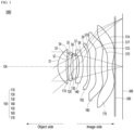
- FIG. 1 is a configuration diagram of an optical system according to a first embodiment
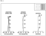
- FIG. 2 is a graph illustrating aberration characteristics of the optical system according to the first embodiment.
- the optical system 1000 may include a first lens 110, a second lens 120, a third lens 130, a fourth lens 140, a fifth lens 150, a sixth lens 160, a seventh lens 170, and an image sensor 300 sequentially arranged from the object side to the image side.
- the first to seventh lenses 110, 120, 130, 140, 150, 160, and 170 may be sequentially disposed along the optical axis OA of the optical system 1000.
- an aperture stop (not shown) may be disposed between the second lens 120 and the third lens 130.
- a filter 500 may be disposed between the plurality of lenses 100 and the image sensor 300.
- the filter 500 may be disposed between the seventh lens 170 and the image sensor 300.
- Table 1 shows a radius of curvature of the first to seventh lenses 110, 120, 130, 140, 150, 160, and 170 according to the first embodiment, a thickness of each lens, the interval between lenses, respectively, the refractive index, the Abbe's Number, and the effective radius (Semi-aperture).
- the first lens 110 of the optical system 1000 according to the first embodiment may have a positive refractive power.
- the first surface S1 of the first lens 110 may be convex, and the second surface S2 may be concave.
- the first lens 110 may have a meniscus shape convex toward the object side.
- the first surface S1 may be an aspherical surface, and the second surface S2 may be an aspherical surface.
- the second lens 120 may have negative (-) refractive power.
- the third surface S3 of the second lens 120 may be convex, and the fourth surface S4 may be concave.
- the second lens 120 may have a meniscus shape convex toward the object side.
- the third surface S3 may be an aspherical surface, and the fourth surface S4 may be an aspherical surface.
- the third lens 130 may have positive (+) refractive power.
- the fifth surface S5 of the third lens 130 may be concave, and the sixth surface S6 may be convex.
- the third lens 130 may have a meniscus shape convex toward the image side.
- the fifth surface S5 may be an aspherical surface
- the sixth surface S6 may be an aspherical surface.
- the fourth lens 140 may have negative (-) refractive power.
- the seventh surface S7 of the fourth lens 140 may be concave, and the eighth surface S8 may be convex.
- the fourth lens 140 may have a meniscus shape convex toward the image side.
- the seventh surface S7 may be an aspherical surface, and the eighth surface S8 may be an aspherical surface.
- the fifth lens 150 may have positive (+) refractive power.
- the ninth surface S9 of the fifth lens 150 may be convex, and the tenth surface S10 may be concave.
- the fifth lens 150 may have a meniscus shape convex toward the object side.
- the ninth surface S9 may be an aspherical surface, and the tenth surface S10 may be an aspherical surface.
- the sixth lens 160 may have positive (+) refractive power.
- the eleventh surface S11 of the sixth lens 160 may be convex, and the twelfth surface S12 may be concave.
- the sixth lens 160 may have a meniscus shape convex toward the object side.
- the seventh lens 170 may have negative (-) refractive power.
- the thirteenth surface S13 of the seventh lens 170 may be convex, and the fourteenth surface S14 may be concave.
- the seventh lens 170 may have a meniscus shape convex toward the object side.
- the thirteenth surface S13 may be an aspherical surface
- the fourteenth surface S14 may be an aspherical surface.
- Table 3 relates to the items of the above-described equations in the optical system 1000 according to the first embodiment, and relates TTL (total track length), BFL (back focal length), F value, ImgH, and Focal lengths f1, f2, f3, f4, f5, f6, and f7 of each of the first to seventh lenses 110, 120, 130, 140, 150, 160, and 170 and the entrance pupil diameter (EPD), etc.
- Table 4 shows the result values of Equations 1 to 27 described above in the optical system 1000 according to the first embodiment. Referring to Table 4, it may be seen that the optical system 1000 according to the first embodiment satisfies at least one of Equations 1 to 27. In detail, it may be seen that the optical system 1000 according to the first embodiment satisfies all of Equations 1 to 27 above.
- the optical system 1000 according to the first embodiment may be provided with a slimmer structure.
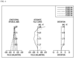
- the optical system 1000 may have improved optical characteristics and aberration characteristics as shown in FIG. 2 .
- FIG. 2 is a graph of the aberration characteristics of the optical system 1000 according to the first embodiment, and this is graph measuring longitudinal spherical aberration, astigmatic field curves, and distortion aberration from left to right.
- the X-axis may indicate a focal length (mm) and distortion (%)
- the Y-axis may indicate the height of an image side.
- the graph for spherical aberration is a graph for light in a wavelength band of about 470 nm, about 510 nm, about 555 nm, about 610 nm, and about 650 nm
- the graph for astigmatism and distortion aberration is a graph for light in a wavelength band of 555 nm.
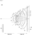
- FIG. 3 is a configuration diagram of an optical system according to a second embodiment
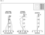
- FIG. 4 is a graph illustrating aberration characteristics of the optical system according to the second embodiment.
- the optical system 1000 may include a first lens 110, a second lens 120, a third lens 130, a fourth lens 140, a fifth lens 150, a sixth lens 160, a seventh lens 170, and an image sensor 300 sequentially disposed along the optical axis OA of the optical system 1000 from the object side to the image side.
- the first to seventh lenses 110, 120, 130, 140, 150, 160, and 170 may be sequentially disposed along the optical axis OA of the optical system 1000.
- an aperture stop (not shown) may be disposed between the second lens 120 and the third lens 130.
- a filter 500 may be disposed between the plurality of lenses 100 and the image sensor 300. In detail, the filter 500 may be disposed between the seventh lens 170 and the image sensor 300.
- Table 5 shows the radius of curvature of the first to seventh lenses 110, 120, 130, 140, 150, 160, and 170 according to the second embodiment, the thickness of each lens, the interval between lenses, respectively, the refractive index, the Abbe's Number, and the effective radius (Semi-aperture).
- the first lens 110 of the optical system 1000 according to the second embodiment may have a positive refractive power.
- the first surface S1 of the first lens 110 may be convex, and the second surface S2 may be concave.
- the first lens 110 may have a meniscus shape convex toward the object side.
- the first surface S1 may be an aspherical surface
- the second surface S2 may be an aspherical surface.
- the second lens 120 may have negative (-) refractive power.
- the third surface S3 of the second lens 120 may be convex, and the fourth surface S4 may be concave.
- the second lens 120 may have a meniscus shape convex toward the object side.
- the third surface S3 may be an aspherical surface, and the fourth surface S4 may be an aspherical surface.
- the third lens 130 may have positive (+) refractive power.
- the fifth surface S5 of the third lens 130 may be concave, and the sixth surface S6 may be convex.
- the third lens 130 may have a meniscus shape convex toward the image side.
- the fifth surface S5 may be an aspherical surface
- the sixth surface S6 may be an aspherical surface.
- the fourth lens 140 may have negative (-) refractive power.
- the seventh surface S7 of the fourth lens 140 may be concave, and the eighth surface S8 may be convex.
- the fourth lens 140 may have a meniscus shape convex toward the image side.
- the seventh surface S7 may be an aspherical surface, and the eighth surface S8 may be an aspherical surface.
- the fifth lens 150 may have positive (+) refractive power.
- the ninth surface S9 of the fifth lens 150 may be convex, and the tenth surface S10 may be concave.
- the fifth lens 150 may have a meniscus shape convex toward the object side.
- the ninth surface S9 may be an aspherical surface, and the tenth surface S10 may be an aspherical surface.
- the sixth lens 160 may have positive (+) refractive power.
- the eleventh surface S11 of the sixth lens 160 may be convex, and the twelfth surface S12 may be concave.
- the sixth lens 160 may have a meniscus shape convex toward the object side.
- the seventh lens 170 may have negative (-) refractive power.
- the thirteenth surface S13 of the seventh lens 170 may be convex, and the fourteenth surface S14 may be concave.
- the seventh lens 170 may have a meniscus shape convex toward the object side.
- the thirteenth surface S13 may be an aspherical surface
- the fourteenth surface S14 may be an aspherical surface.
- Table 7 relates to the items of the above-described equations in the optical system 1000 according to the second embodiment, and relates TTL (total track length), BFL (back focal length), F value, ImgH, and Focal lengths f1, f2, f3, f4, f5, f6, and f7 of each of the first to seventh lenses 110, 120, 130, 140, 150, 160, and 170 and the entrance pupil diameter (EPD), etc.
- Table 8 shows the result values of Equations 1 to 27 described above in the optical system 1000 according to the second embodiment. Referring to Table 8, it may be seen that the optical system 1000 according to the second embodiment satisfies at least one of Equations 1 to 27. In detail, it may be seen that the optical system 1000 according to the second embodiment satisfies all of Equations 1 to 27 above.
- the optical system 1000 according to the second embodiment may be provided with a slimmer structure.
- the optical system 1000 may have improved optical characteristics and aberration characteristics as shown in FIG. 4 .
- FIG. 4 is a graph of the aberration characteristics of the optical system 1000 according to the second embodiment, and this is graph measuring longitudinal spherical aberration, astigmatic field curves, and distortion aberration from left to right.
- the X-axis may indicate a focal length (mm) and distortion (%)
- the Y-axis may indicate the height of an image side.
- the graph for spherical aberration is a graph for light in a wavelength band of about 470 nm, about 510 nm, about 555 nm, about 610 nm, and about 650 nm
- the graph for astigmatism and distortion aberration is a graph for light in a wavelength band of 555 nm.
- FIG. 5 is a configuration diagram of an optical system according to the third embodiment
- FIG. 6 is a graph illustrating aberration characteristics of the optical system according to the third embodiment.
- the optical system 1000 may include a first lens 110, a second lens 120, a third lens 130, a fourth lens 140, a fifth lens 150, a sixth lens 160, a seventh lens 170, and an image sensor 300 sequentially disposed along the optical axis OA of the optical system 1000 from the object side to the image side.
- an aperture stop (not shown) may be disposed between the second lens 120 and the third lens 130.
- a filter 500 may be disposed between the plurality of lenses 100 and the image sensor 300.
- the filter 500 may be disposed between the seventh lens 170 and the image sensor 300.
- Table 9 shows the radius of curvature of the first to seventh lenses 110, 120, 130, 140, 150, 160, and 170 according to the third embodiment, the thickness of each lens, the interval between lenses, respectively, the refractive index, the Abbe's Number, and the effective radius (Semi-aperture).
- the first lens 110 of the optical system 1000 according to the third embodiment may have a positive refractive power.
- the first surface S1 of the first lens 110 may be convex, and the second surface S2 may be concave.
- the first lens 110 may have a meniscus shape convex toward the object side.
- the first surface S1 may be an aspherical surface
- the second surface S2 may be an aspherical surface.
- the second lens 120 may have negative (-) refractive power.
- the third surface S3 of the second lens 120 may be convex, and the fourth surface S4 may be concave.
- the second lens 120 may have a meniscus shape convex toward the object side.
- the third surface S3 may be an aspherical surface, and the fourth surface S4 may be an aspherical surface.
- the third lens 130 may have positive (+) refractive power.
- the fifth surface S5 of the third lens 130 may be concave, and the sixth surface S6 may be convex.
- the third lens 130 may have a meniscus shape convex toward the image side.
- the fifth surface S5 may be an aspherical surface
- the sixth surface S6 may be an aspherical surface.
- the fourth lens 140 may have negative (-) refractive power.
- the seventh surface S7 of the fourth lens 140 may be concave, and the eighth surface S8 may be convex.
- the fourth lens 140 may have a meniscus shape convex toward the image side.
- the seventh surface S7 may be an aspherical surface, and the eighth surface S8 may be an aspherical surface.
- the fifth lens 150 may have positive (+) refractive power.
- the ninth surface S9 of the fifth lens 150 may be convex, and the tenth surface S10 may be concave.
- the fifth lens 150 may have a meniscus shape convex toward the object side.
- the ninth surface S9 may be an aspherical surface, and the tenth surface S10 may be an aspherical surface.
- the sixth lens 160 may have positive (+) refractive power.
- the eleventh surface S11 of the sixth lens 160 may be convex, and the twelfth surface S12 may be concave.
- the sixth lens 160 may have a meniscus shape convex toward the object side.
- the seventh lens 170 may have negative (-) refractive power.
- the thirteenth surface S13 of the seventh lens 170 may be convex, and the fourteenth surface S14 may be concave.
- the seventh lens 170 may have a meniscus shape convex toward the object side.
- the thirteenth surface S13 may be an aspherical surface
- the fourteenth surface S14 may be an aspherical surface.
- Table 11 is for the items of the above-described equations in the optical system 1000 according to the third embodiment, and relates TTL (total track length), BFL (back focal length), F value, ImgH, and Focal lengths f1, f2, f3, f4, f5, f6, and f7 of each of the first to seventh lenses 110, 120, 130, 140, 150, 160, and 170 and the entrance pupil diameter (EPD), etc.
- Table 12 shows the result values of Equations 1 to 27 described above in the optical system 1000 according to the third embodiment. Referring to Table 12, it may be seen that the optical system 1000 according to the third embodiment satisfies at least one of Equations 1 to 27. In detail, it may be seen that the optical system 1000 according to the third embodiment satisfies all of Equations 1 to 27 above.
- the optical system 1000 according to the third embodiment may be provided with a slimmer structure.
- the optical system 1000 may have improved optical characteristics and aberration characteristics as shown in FIG. 6 .
- FIG. 6 is a graph of the aberration characteristics of the optical system 1000 according to the third embodiment, and this is graph measuring longitudinal spherical aberration, astigmatic field curves, and distortion aberration from left to right.
- the X-axis may indicate a focal length (mm) and distortion (%)
- the Y-axis may indicate the height of an image side.
- the graph for spherical aberration is a graph for light in a wavelength band of about 470 nm, about 510 nm, about 555 nm, about 610 nm, and about 650 nm
- the graph for astigmatism and distortion aberration is a graph for light in a wavelength band of 555 nm.
- the optical system 1000 may satisfy at least one of the above-described equations. Accordingly, the optical system 1000 may block unnecessary light rays entering the optical system 1000 to improve aberration characteristics. Accordingly, the optical system 1000 may have improved optical characteristics and may have a slimmer structure.
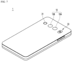
- FIG. 7 is a diagram illustrating that the camera module according to the embodiment is applied to a mobile terminal.
- the mobile terminal 1 may include a camera module 10 provided on the rear side.
- the camera module 10 may include an image capturing function.
- the camera module 10 may include at least one of an auto focus function, a zoom function, and an OIS function.
- the camera module 10 may process a still video image or an image frame of a moving image obtained by the image sensor 300 in a shooting mode or a video call mode.
- the processed image frame may be displayed on a display unit (not shown) of the mobile terminal 1 and may be stored in a memory (not shown).
- the camera module may be further disposed on the front of the mobile terminal 1.
- the camera module 10 may include a first camera module 10A and a second camera module 10B.
- the mobile terminal 1 may further include an autofocus device 31.
- the auto focus device 31 may include an auto focus function using a laser.
- the auto focus device 31 may be mainly used in a condition in which the auto focus function using the image of the camera module 10 is deteriorated, for example, in proximity of 10 m or less or in a dark environment.
- the autofocus device 31 may include a light emitting unit including a VCSEL (vertical cavity surface emission laser) semiconductor device and a light receiving unit that converts light energy such as a photodiode into electrical energy.
- the mobile terminal 1 may further include a flash module 33.
- the flash module 33 may include a light emitting device emitting light therein. The flash module 33 may be operated by a camera operation of a mobile terminal or a user's control.
Landscapes
- Physics & Mathematics (AREA)
- General Physics & Mathematics (AREA)
- Optics & Photonics (AREA)
- Engineering & Computer Science (AREA)
- Multimedia (AREA)
- Signal Processing (AREA)
- Lenses (AREA)
Applications Claiming Priority (2)
| Application Number | Priority Date | Filing Date | Title |
|---|---|---|---|
| KR1020200172417A KR20220082470A (ko) | 2020-12-10 | 2020-12-10 | 광학계 및 이를 포함하는 카메라 모듈 |
| PCT/KR2021/018766 WO2022124855A1 (fr) | 2020-12-10 | 2021-12-10 | Système optique et module de caméra le comprenant |
Publications (2)
| Publication Number | Publication Date |
|---|---|
| EP4261588A1 true EP4261588A1 (fr) | 2023-10-18 |
| EP4261588A4 EP4261588A4 (fr) | 2024-06-05 |
Family
ID=81974549
Family Applications (1)
| Application Number | Title | Priority Date | Filing Date |
|---|---|---|---|
| EP21903900.5A Pending EP4261588A4 (fr) | 2020-12-10 | 2021-12-10 | Système optique et module de caméra le comprenant |
Country Status (7)
| Country | Link |
|---|---|
| US (1) | US20240045177A1 (fr) |
| EP (1) | EP4261588A4 (fr) |
| JP (1) | JP2023553446A (fr) |
| KR (1) | KR20220082470A (fr) |
| CN (1) | CN116710825A (fr) |
| TW (1) | TW202238207A (fr) |
| WO (1) | WO2022124855A1 (fr) |
Families Citing this family (4)
| Publication number | Priority date | Publication date | Assignee | Title |
|---|---|---|---|---|
| KR20220093970A (ko) * | 2020-12-28 | 2022-07-05 | 엘지이노텍 주식회사 | 광학계 및 이를 포함하는 카메라 모듈 |
| CN112748532B (zh) * | 2020-12-29 | 2024-09-27 | 常州市瑞泰光电有限公司 | 摄像光学镜头 |
| TWI860929B (zh) * | 2023-08-17 | 2024-11-01 | 先進光電科技股份有限公司 | 光學成像鏡頭 |
| CN119511505B (zh) * | 2024-12-31 | 2026-04-21 | 常州市瑞泰光电有限公司 | 摄像光学镜头 |
Family Cites Families (18)
| Publication number | Priority date | Publication date | Assignee | Title |
|---|---|---|---|---|
| JP5963360B2 (ja) * | 2012-11-21 | 2016-08-03 | カンタツ株式会社 | 撮像レンズ |
| JP6160423B2 (ja) * | 2013-10-04 | 2017-07-12 | コニカミノルタ株式会社 | 撮像レンズ、撮像装置及び携帯端末 |
| JP2015114505A (ja) * | 2013-12-12 | 2015-06-22 | コニカミノルタ株式会社 | 撮像レンズ及び撮像装置 |
| JP6226295B2 (ja) * | 2014-01-10 | 2017-11-08 | 株式会社オプトロジック | 撮像レンズ |
| JP6226296B2 (ja) * | 2014-01-10 | 2017-11-08 | 株式会社オプトロジック | 撮像レンズ |
| TWI510804B (zh) * | 2014-08-01 | 2015-12-01 | Largan Precision Co Ltd | 取像用光學鏡組、取像裝置及電子裝置 |
| KR102080657B1 (ko) * | 2016-12-26 | 2020-02-24 | 삼성전기주식회사 | 촬상 광학계 |
| KR102776263B1 (ko) * | 2016-12-28 | 2025-03-07 | 삼성전기주식회사 | 촬상 광학계 |
| JP6363782B1 (ja) * | 2017-10-19 | 2018-07-25 | エーエーシー テクノロジーズ ピーティーイー リミテッドAac Technologies Pte.Ltd. | 撮像光学レンズ |
| JP6388703B1 (ja) * | 2017-10-19 | 2018-09-12 | エーエーシー テクノロジーズ ピーティーイー リミテッドAac Technologies Pte.Ltd. | 撮像光学レンズ |
| JP6375433B1 (ja) * | 2017-10-30 | 2018-08-15 | エーエーシー テクノロジーズ ピーティーイー リミテッドAac Technologies Pte.Ltd. | 撮像光学レンズ |
| CN108107555B (zh) * | 2017-12-29 | 2019-11-26 | 玉晶光电(厦门)有限公司 | 光学成像镜头 |
| CN113687497B (zh) * | 2018-05-29 | 2024-02-09 | 三星电机株式会社 | 光学成像系统 |
| KR102081311B1 (ko) * | 2018-05-29 | 2020-02-25 | 삼성전기주식회사 | 촬상 광학계 |
| CN109491051B (zh) * | 2018-12-28 | 2021-05-28 | 诚瑞光学(常州)股份有限公司 | 摄像光学镜头 |
| JP6858466B2 (ja) * | 2018-12-29 | 2021-04-14 | カンタツ株式会社 | 撮像レンズ |
| JP6843476B2 (ja) * | 2019-05-13 | 2021-03-17 | カンタツ株式会社 | 撮像レンズ |
| CN110361836B (zh) * | 2019-06-29 | 2021-09-21 | 瑞声光学解决方案私人有限公司 | 摄像光学镜头 |
-
2020
- 2020-12-10 KR KR1020200172417A patent/KR20220082470A/ko active Pending
-
2021
- 2021-12-10 JP JP2023535544A patent/JP2023553446A/ja active Pending
- 2021-12-10 CN CN202180090074.7A patent/CN116710825A/zh active Pending
- 2021-12-10 TW TW110146419A patent/TW202238207A/zh unknown
- 2021-12-10 WO PCT/KR2021/018766 patent/WO2022124855A1/fr not_active Ceased
- 2021-12-10 US US18/256,944 patent/US20240045177A1/en active Pending
- 2021-12-10 EP EP21903900.5A patent/EP4261588A4/fr active Pending
Also Published As
| Publication number | Publication date |
|---|---|
| KR20220082470A (ko) | 2022-06-17 |
| CN116710825A (zh) | 2023-09-05 |
| US20240045177A1 (en) | 2024-02-08 |
| TW202238207A (zh) | 2022-10-01 |
| JP2023553446A (ja) | 2023-12-21 |
| EP4261588A4 (fr) | 2024-06-05 |
| WO2022124855A1 (fr) | 2022-06-16 |
Similar Documents
| Publication | Publication Date | Title |
|---|---|---|
| US12487433B2 (en) | Optical system comprising first to seventh lenses sequentially arranged along an optical axis and camera module comprising the same | |
| EP4261588A1 (fr) | Système optique et module de caméra le comprenant | |
| US20240302629A1 (en) | Optical system and camera module comprising same | |
| KR20230013988A (ko) | 광학계 및 이를 포함하는 광학 모듈 및 카메라 모듈 | |
| US20240353653A1 (en) | Optical system and camera module comprising same | |
| CN117529681A (zh) | 光学系统以及包括光学系统的摄像装置模块 | |
| KR20220169216A (ko) | 광학계 및 이를 포함하는 카메라 모듈 | |
| KR20220132993A (ko) | 광학계 및 이를 포함하는 카메라 모듈 | |
| EP4261586A1 (fr) | Système optique et module de caméra le comprenant | |
| EP4209816A1 (fr) | Système optique et module de caméra comprenant celui-ci | |
| EP4455755A1 (fr) | Système optique, et module optique et module de caméra le comprenant | |
| EP4261589A1 (fr) | Système optique et module de caméra le comprenant | |
| US20250013010A1 (en) | Optical system and camera module comprising same | |
| US12481134B2 (en) | Optical system and camera module comprising same | |
| US20240094509A1 (en) | Optical system | |
| KR20230162392A (ko) | 광학계 및 이를 포함하는 카메라 모듈 | |
| KR20240035578A (ko) | 광학계 및 이를 포함하는 광학 모듈 및 카메라 모듈 | |
| CN117529680A (zh) | 光学系统以及包括光学系统的摄像装置模块 | |
| US12474550B2 (en) | Optical system comprising seven lenses and camera module comprising the same | |
| KR20230094152A (ko) | 광학계, 이를 포함하는 광학 모듈 및 카메라 모듈 | |
| KR20220148028A (ko) | 광학계 | |
| KR20230162391A (ko) | 광학계 및 이를 포함하는 카메라 모듈 |
Legal Events
| Date | Code | Title | Description |
|---|---|---|---|
| STAA | Information on the status of an ep patent application or granted ep patent |
Free format text: STATUS: THE INTERNATIONAL PUBLICATION HAS BEEN MADE |
|
| PUAI | Public reference made under article 153(3) epc to a published international application that has entered the european phase |
Free format text: ORIGINAL CODE: 0009012 |
|
| STAA | Information on the status of an ep patent application or granted ep patent |
Free format text: STATUS: REQUEST FOR EXAMINATION WAS MADE |
|
| 17P | Request for examination filed |
Effective date: 20230705 |
|
| AK | Designated contracting states |
Kind code of ref document: A1 Designated state(s): AL AT BE BG CH CY CZ DE DK EE ES FI FR GB GR HR HU IE IS IT LI LT LU LV MC MK MT NL NO PL PT RO RS SE SI SK SM TR |
|
| DAV | Request for validation of the european patent (deleted) | ||
| DAX | Request for extension of the european patent (deleted) | ||
| A4 | Supplementary search report drawn up and despatched |
Effective date: 20240503 |
|
| RIC1 | Information provided on ipc code assigned before grant |
Ipc: H04N 23/55 20230101ALI20240427BHEP Ipc: G02B 13/02 20060101ALI20240427BHEP Ipc: G03B 17/12 20210101ALI20240427BHEP Ipc: G02B 3/00 20060101ALI20240427BHEP Ipc: G02B 9/64 20060101ALI20240427BHEP Ipc: G02B 13/00 20060101AFI20240427BHEP |
|
| STAA | Information on the status of an ep patent application or granted ep patent |
Free format text: STATUS: EXAMINATION IS IN PROGRESS |