EP4261643A1 - Système de robot de travail - Google Patents
Système de robot de travail Download PDFInfo
- Publication number
- EP4261643A1 EP4261643A1 EP20965129.8A EP20965129A EP4261643A1 EP 4261643 A1 EP4261643 A1 EP 4261643A1 EP 20965129 A EP20965129 A EP 20965129A EP 4261643 A1 EP4261643 A1 EP 4261643A1
- Authority
- EP
- European Patent Office
- Prior art keywords
- wire
- working robot
- working
- robot system
- area
- Prior art date
- Legal status (The legal status is an assumption and is not a legal conclusion. Google has not performed a legal analysis and makes no representation as to the accuracy of the status listed.)
- Pending
Links
Images





Classifications
-
- G—PHYSICS
- G05—CONTROLLING; REGULATING
- G05D—SYSTEMS FOR CONTROLLING OR REGULATING NON-ELECTRIC VARIABLES
- G05D1/00—Control of position, course, altitude or attitude of land, water, air or space vehicles, e.g. using automatic pilots
- G05D1/02—Control of position or course in two dimensions
- G05D1/021—Control of position or course in two dimensions specially adapted to land vehicles
- G05D1/0212—Control of position or course in two dimensions specially adapted to land vehicles with means for defining a desired trajectory
- G05D1/0214—Control of position or course in two dimensions specially adapted to land vehicles with means for defining a desired trajectory in accordance with safety or protection criteria, e.g. avoiding hazardous areas
-
- A—HUMAN NECESSITIES
- A01—AGRICULTURE; FORESTRY; ANIMAL HUSBANDRY; HUNTING; TRAPPING; FISHING
- A01D—HARVESTING; MOWING
- A01D34/00—Mowers; Mowing apparatus of harvesters
- A01D34/006—Control or measuring arrangements
- A01D34/008—Control or measuring arrangements for automated or remotely controlled operation
-
- A—HUMAN NECESSITIES
- A63—SPORTS; GAMES; AMUSEMENTS
- A63B—APPARATUS FOR PHYSICAL TRAINING, GYMNASTICS, SWIMMING, CLIMBING, OR FENCING; BALL GAMES; TRAINING EQUIPMENT
- A63B47/00—Devices for handling or treating balls, e.g. for holding or carrying balls
- A63B47/02—Devices for handling or treating balls, e.g. for holding or carrying balls for picking-up or collecting
-
- G—PHYSICS
- G05—CONTROLLING; REGULATING
- G05D—SYSTEMS FOR CONTROLLING OR REGULATING NON-ELECTRIC VARIABLES
- G05D1/00—Control of position, course, altitude or attitude of land, water, air or space vehicles, e.g. using automatic pilots
- G05D1/02—Control of position or course in two dimensions
- G05D1/021—Control of position or course in two dimensions specially adapted to land vehicles
- G05D1/0257—Control of position or course in two dimensions specially adapted to land vehicles using a radar
-
- G—PHYSICS
- G05—CONTROLLING; REGULATING
- G05D—SYSTEMS FOR CONTROLLING OR REGULATING NON-ELECTRIC VARIABLES
- G05D1/00—Control of position, course, altitude or attitude of land, water, air or space vehicles, e.g. using automatic pilots
- G05D1/20—Control system inputs
- G05D1/24—Arrangements for determining position or orientation
- G05D1/244—Arrangements for determining position or orientation using passive navigation aids external to the vehicle, e.g. markers, reflectors or magnetic means
-
- G—PHYSICS
- G05—CONTROLLING; REGULATING
- G05D—SYSTEMS FOR CONTROLLING OR REGULATING NON-ELECTRIC VARIABLES
- G05D1/00—Control of position, course, altitude or attitude of land, water, air or space vehicles, e.g. using automatic pilots
- G05D1/40—Control within particular dimensions
- G05D1/43—Control of position or course in two dimensions [2D]
-
- A—HUMAN NECESSITIES
- A01—AGRICULTURE; FORESTRY; ANIMAL HUSBANDRY; HUNTING; TRAPPING; FISHING
- A01D—HARVESTING; MOWING
- A01D2101/00—Lawn-mowers
-
- A—HUMAN NECESSITIES
- A01—AGRICULTURE; FORESTRY; ANIMAL HUSBANDRY; HUNTING; TRAPPING; FISHING
- A01D—HARVESTING; MOWING
- A01D34/00—Mowers; Mowing apparatus of harvesters
- A01D34/01—Mowers; Mowing apparatus of harvesters characterised by features relating to the type of cutting apparatus
- A01D34/412—Mowers; Mowing apparatus of harvesters characterised by features relating to the type of cutting apparatus having rotating cutters
- A01D34/63—Mowers; Mowing apparatus of harvesters characterised by features relating to the type of cutting apparatus having rotating cutters having cutters rotating about a vertical axis
- A01D34/64—Mowers; Mowing apparatus of harvesters characterised by features relating to the type of cutting apparatus having rotating cutters having cutters rotating about a vertical axis mounted on a vehicle, e.g. a tractor, or drawn by an animal or a vehicle
-
- G—PHYSICS
- G05—CONTROLLING; REGULATING
- G05D—SYSTEMS FOR CONTROLLING OR REGULATING NON-ELECTRIC VARIABLES
- G05D2109/00—Types of controlled vehicles
- G05D2109/10—Land vehicles
Definitions
- the present invention relates to a working robot system.
- an area required for the working robot to work (working area) is surrounded by using a conductive wire.
- the conductive wire is connected to a power supply facility configured to charge the working robot, and electricity is conducted through the conductive wire to release a magnetic field around the conductive wire.
- a magnetic sensor is attached to the front end of the working robot to detect the magnetic field released from the conductive wire conducting the electricity.
- the power supply facility connected to the conductive wire is broken down due to lightning strike and so forth, so that it is not possible to conduct the conductive wire, or the electric conduction of the conductive wire is broken at breaking or blackout.
- the conventional working robot described above cannot recognize the boundary of the working area because the magnetic field released from the wire disappears, and therefore cannot continue the work.
- a working robot configured to recognize the area by using a transmission facility (beacon). Also in this case, when battery exhaustion or breakdown occurs in the beacon, the working robot cannot recognize the area, and therefore cannot continue the work.
- the present invention has been achieved to solve the above-described problem. It is therefore an object of the invention to solve the problem that the working robot cannot recognize the area when breakdown or blackout of the power supply facility occurs, and to allow the working robot to continue the work in a stable manner.
- a working robot system includes a working robot configured to perform work while autonomously traveling, and a non-energization wire configured to partition a working area or an active area of the working robot.
- the working robot includes a wire detector configured to detect the wire.
- the working robot system includes a controller configured to control the working robot to autonomously travel within an area partitioned by the wire, based on a detection signal from the wire detector.
- the working robot system having the above-described features, it is possible to solve the problem that the working robot cannot recognize the area, and to allow the working robot to continue the work in a stable manner.
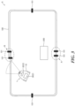
- a working robot system S includes a working robot 1 configured to perform work while autonomously traveling, and a wire 100 configured to partition a working area or an active area of the working robot 1.
- the working area is an area in which the working robot 1 performs work
- the active area is an area in which activities of the working robot 1, including the traveling in and out of the working area, are permitted.
- the working robot 1 is configured to perform work in, for example, a construction site, a ridge, an orchard, a mountain, a grassland, a garden, and a sports practice area.
- the kinds of work are not particularly limited, but the working robot 1 may be a lawn mower to perform lawn mowing, a grass mower to mow grass such as weeds, and a ball picker to collect balls.
- the wire 100 is a non-energization wire.
- “non-energization” means “electricity is not conducted”, and therefore there is no need to be electrically connected to a power supply facility.
- a charging station (power supply facility) 200 configured to charge the working robot 1 may be provided in the area surrounded by the wire 100. Also in this case, the wire 100 is not electrically connected to the charging station 200.
- the wire 100 may be endless as illustrated in Fig. 1 , or may have one end and the other end as illustrated in Fig. 2 and Fig. 3 .
- one area may be surrounded by using one wire 100 as illustrated in Fig. 1 and Fig. 2 , or by using more than one (at least two) wires 100 having ends as illustrated in Fig. 3 .
- connectors 102 may be provided at the ends, respectively, to connect the ends to one another as illustrated in Fig. 2 ; the ends may be fixed by one or more fixing members 101 as illustrated in Fig. 3 ; the ends may be close to but spaced from one another as illustrated in Fig. 3 -A; or the ends may overlap one another as illustrated in Fig. 3 -B.
- a male screw is provided at one (connector 102A) of the connectors connected to one another, and a female screw is provided at the other (connector 102B) to connect the ends to one another;
- a clip is provided at one (connector 102A) or the other (connector 102B) of the connectors to connect the ends to one another; or, for example, a coupler may be used such that one end is inserted into a sleeve connection member from one side, and the other end is inserted into the sleeve connection member from the other side to connect the ends to one another.
- the wire 100 may be provided on a working surface on which the working robot 1 performs the work, which is a flat surface or an inclined surface on the ground. In addition, part or the whole of the wire 100 may be provided in the ground. When the wire 100 is provided, the wire 100 may not be fixed so as to allow it to be easily installed, removed, and reinstalled, or may be fixed so as not to be easily moved.
- the working robot system S includes fixing members 101 to fix the wire 100.
- the fixing members 101 configured to mechanically fix the wire 100 to the ground may be used.
- the fixing members 101 are dispersed at predetermined intervals as illustrated in Fig. 1 , and by this means, part of the wire 100 can be fixed to the ground.
- the wire 100 when the wire 100 has ends, it is preferred that, in particular, one end and the other end of the wire 100 are fixed to one another by the fixing members 101 as illustrated in Fig. 2 and Fig. 3 .
- Pegs may be used as the fixing members 101 to make it easy to remove and reinstall the wire 100.
- one end and the other end of the wire 100 may be fixed to one another by a fixing part 103 different from the fixing members 101 as illustrated in Fig. 2 .
- the wire 100 may have any form, such as a flexible form and a rigid form.
- a flexible form and a rigid form.
- the wire 100 may be permanently provided, or temporarily provided only during the work, to surround the area.
- the flexible wire 100 may be used in such a way that: the area targeted for the work is optionally specified before the work, and the wire 100 is provided there; and then, after this work is finished, another working area is optionally specified, and the wire 100 is moved there.
- the working robot 1 includes conventionally known components that allow autonomous travel, and in addition, includes a wire detector 2 configured to detect the wire 100.
- the working robot system S includes a controller 3 configured to control the working robot 1 to autonomously travel within the area surrounded by the wire 100 based on a detection signal from the wire detector 2.
- a sensor unit 20 is provided at the front end of the working robot 1, and includes the wire detector 2.
- a controller 30 is provided in a body 10 of the working robot 1 as the controller 3 of the working robot system S.
- the controller 3 of the working robot system S may be installed in a station (for example, the charging station 200 and any other management station (not illustrated)) to remotely control the working robot 1.
- the wire detector 2 will be described.
- the wire detector 2 may not be limited as long as it allows the controller 3 to recognize the presence of the non-energization wire 100.
- a wire detection sensor configured to transmit a detection wave to the wire 100 and receive a reflected wave from the wire 100 may be used.
- the wire detection sensor is a sensor configured to detect the non-energization wire 100, for example, by a radar.
- a sensor configured to detect the wire 100 by using a detection wave at a frequency equal to or higher than an extremely high frequency.
- the illustrated working robot 1 includes a battery 11 in the body 10, and traveling members 12 configured to allow the autonomous travel by supplying the electricity from the battery 11.
- the body 10 includes a working device 13 configured to perform the work along a traveling route of the body 10.
- the working robot 1 includes the controller 30 configured to control the traveling members 12 and the working device 13.
- the illustrated traveling members 12 of the working robot 1 include front wheel traveling members 12A and rear wheel traveling members 12B, and are configured to allow the body 10 to autonomously travel toward any direction within the area surrounded by the wire 100.
- the body 10 of the working robot 1 includes actuators 14 configured to actuate the traveling members 12 and the working device 13.
- the actuators 14 include a pair of right and left front wheel actuators 14A, a pair of right and left rear wheel actuators 14B, and a working actuator 14C configured to actuate the working device 13.
- the battery 11 is a power source for the actuators 14, the controller 30 and so forth.
- the working device 13 of the working robot 1 is configured to perform mowing work to mow lawn and weeds, or collection work to collect balls, so that a working track is formed along the traveling route of the body 10.
- the working device 13 configured to perform the mowing work to mow lawn and weeds will be described.
- the working device 3 has a circular working range in a plan view, and mows grass just under the working device 13 by rotating a mowing blade (not illustrated) around a vertical axis. Therefore, when the working device 13 is actuated while the body 10 is traveling, the working track through which the mowing work is done is formed along the traveling route of the working robot 1.
- the width of the working track is the diameter of the circular working range of the working device 13 in a plane view.
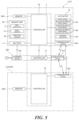
- the working robot system S has a control system for the autonomous travel, which is established by the working robot 1, the charging station 200 including a charging device 201, and a management server 210 or a personal digital assistant 220 belonging to a worker, for example, as illustrated in Fig. 5 .
- the controller 30 of the working robot 1, a controller 31 of the charging station 200, and a controller 32 of the management server 210 (or the personal digital assistant 220) include communication devices 30A, 31A, and 32A, respectively.
- the communication devices 30A, 31A, and 32A transmit and receive information to and from each other via a network or radio communication to establish the integrated controller 3 of the working robot system S.
- the sensor unit 20 including the wire detector 2 is provided in the body 10 of the working robot 1.
- the autonomous travel of the working robot 1 is controlled by the controller 3 based on the detection signal from the wire detector 2.
- the controller 3 outputs a control command to the traveling members 12 to turn the body 10 to control the working robot 1 to autonomously travel within the area surrounded by the wire 100.
- the sensor unit 20 of the working robot 1 may include a GNSS sensor 21 or a direction sensor 22 so as to be able to virtually set an area for the autonomous travel of the working robot 1 even without the detection signal to detect the wire 100.
- the virtual area for the autonomous travel is set by the controller 3, based on detection signals from the GNNS sensor 21 and the direction sensor 22, and map information stored in memories 30B and 32B.
- the wire 100 includes detection markers 110 as a form feature.
- the controller 3 of the working robot system S can determine whether the working robot 1 exists inside or outside the area surrounded by the wire 100.
- a plurality of detection markers 110 are provided along the longitudinal direction of the wire 100.
- the detection markers 110 are parts made of a material (for example, metal) which can be detected by the wire detector 2, and are attached to the outer surface of the wire 100. As illustrated in Fig. 7 , the distances A, B, C each between two of the four detection markers 110 continuously arranged are different from each other (for example, A ⁇ B ⁇ C).
- a core 100A made of a material (for example, metal) which can be detected by the wire detector 2 is provided inside the wire 100 if necessary.
- the wire detector 2 of the working robot 1 has a function to scan detection waves in one direction (for example, clockwise). For example, when the distances between the detection markers 110 detected by the scanning of the detection waves are in the order of (A, B, C), (B, C, A), or (C, A, B), the controller 3 determines that the working robot 1 exists inside the area surrounded by the wire 100. Meanwhile, when the distances between the detection markers 110 detected are in the order of (C, B, A), (B, A, C), or (A, C, B), the controller 3 determines that the working robot 1 exists outside the area surrounded by the wire 100.
- This working robot system S allows the working robot 1 to autonomously travel, for example, according to the control flow described below. That is, as illustrated in Fig. 8 , after the start of the control, the controller 3 of the working robot 1 does not actuate the working device 13 to perform the predetermined work, but first causes the working robot 1 to turn (step S01) toward the direction (for example, to a location a in Fig. 6 ) to detect the wire 10 based on the detection waves of the wire detector 2. When the wire 100 is detected (step S02: YES), the detection waves are scanned by the wire detector 2 as described above. Then, it is determined whether the working robot 1 exists inside the area surrounded by the wire 100 based on the form feature of the wire 100 (step S03) .
- step S06 when the working robot 1 turns to the location (for example, the location a in Fig. 6 ) where the wire 100 is detected based on the detection waves by the wire detector 2, and the wire 100 cannot be detected (step S02: NO), the detection of the wire 100 is continued until a predetermined period of time has elapsed (step S07: NO). Then, when the state in which the wire 100 cannot be detected is continued and the predetermined period of time has elapsed (step S07: YES), the controller 3 causes the working robot 1 to stop (step S06).
- step S04 controls the traveling members 12 to turn the working robot 1 at a predetermined angle, for example, in the location a in Fig. 6 , and to cause the working robot 1 to travel into the area as indicated by an arrow b in Fig. 6 (step S04) .
- step S06 causes the working robot 1 to stop.
- the working robot 1 continues to perform the predetermined work until the working robot 1 finishes the predetermined work, or the user stops the working robot 1 (step S05: NO).
- Fig. 9 illustrates another example of the configuration where the controller 3 determines whether the working robot 1 exists inside or outside the area surrounded by the wire 100, based on the form feature of the wire 100.
- the wire 100 is combination of a wire 100P which is thick in diameter and a wire 100Q which is thin in diameter. One of them is disposed outside the area surrounded by the wire 100, and the other is disposed inside the area surrounded by the wire 100 (with the illustrated example, the thin wire 100Q is disposed outside and the thick wire 100P is disposed inside, but vice versa is possible).
- the form features of the wire are not limited to those examples.
- the wire 100 surrounding the area has such a form feature that one of the outer surface of the wire 100 facing the inside of the area and the outer surface of the wire 100 facing the outside of the area is uneven.
- the controller 3 of the working robot system S can determine whether the working robot 1 exists outside or inside the area surrounded by the wire 100.
- the working robot system S partitions the working area or the active area of the working robot 1 by using the non-energization wire 100.
- the working robot 1 includes the wire detector 2 configured to be able to detect the non-energization wire 100, and the working robot system S includes the controller 3 configured to control the working robot 1 to autonomously travel within the area partitioned by the wire 100 based on the detection signal from the wire detector 2.
- the working robot system S can partition the working area in any location by using the wire 100, regardless of the power supply facility or the power source. In addition, even when a trouble such as blackout or breaking occurs, the working robot system S can continue the work of the working robot 1 in the area partitioned by the wire 100 regardless of the trouble.
- the setting of the area by using the wire 100 can be combined with the conventional setting of the area by using a beacon or the virtual setting of the area by using a GNSS.
- the boundary of the active area which defines the most outside of the range of activity of the working robot 1 may be set by the beacon, and one or more working areas (the areas targeted for the work of the working robot 1) to be set inside the active area may be set by the wire 100.
- the boundary of the active area may be set by the wire 100, and the working areas to be set inside the active area may be set as a virtual area by utilizing a beacon or a GNSS.
- the wire detection sensor configured to transmit a detection wave from a radar to the wire 100, and receive a reflected wave from the wire 100 can be used.
- a sensor for example, a millimeter wave sensor
- the wire 100 can be precisely detect the wire 100, and even through the detected part of the wire 100 is made of metal, it is possible to eliminate error detection that metal dust in the ground is erroneously detected as the wire 100.
- the wire 100 of the working robot system S is not electrically connected to the charging station (power supply facility) 200 configured to charge the working robot 1. Therefore, it is possible to install a charging facility anywhere inside and outside the area surrounded by the wire 100 as long as a terminal connected to the charging facility to charge the battery 11 of the working robot can be connected to a connecting terminal of the charging facility there.
- the working robot system S can determine whether the working robot 1 exists outside or inside the area surrounded by the wire 100 based on the form features of the wire 100. By this means, it is possible to cause the working device 13 of the working robot 1 to be actuated only within the area surrounded by the wire 100, and therefore to cause the working robot 1 to perform the work only within the safe area.
- the controller 3 may control the traveling members 12 to increase the traveling speed of the working robot 1 only within the area surrounded by the wire 100. By this means, it is possible to improve the work efficiency in the safe area. Furthermore, when a plurality of working robots 1 are centrally controlled, it is possible to achieve efficient management in such a way that only the working robot 1 in the working area surrounded by the wire 100 autonomously travels, and the working robot 1 outside the working area is stopped.
Landscapes
- Engineering & Computer Science (AREA)
- Remote Sensing (AREA)
- Radar, Positioning & Navigation (AREA)
- Automation & Control Theory (AREA)
- Physics & Mathematics (AREA)
- General Physics & Mathematics (AREA)
- Aviation & Aerospace Engineering (AREA)
- Life Sciences & Earth Sciences (AREA)
- Environmental Sciences (AREA)
- Health & Medical Sciences (AREA)
- General Health & Medical Sciences (AREA)
- Physical Education & Sports Medicine (AREA)
- Control Of Position, Course, Altitude, Or Attitude Of Moving Bodies (AREA)
Applications Claiming Priority (1)
| Application Number | Priority Date | Filing Date | Title |
|---|---|---|---|
| PCT/JP2020/046136 WO2022123747A1 (fr) | 2020-12-10 | 2020-12-10 | Système de robot de travail |
Publications (2)
| Publication Number | Publication Date |
|---|---|
| EP4261643A1 true EP4261643A1 (fr) | 2023-10-18 |
| EP4261643A4 EP4261643A4 (fr) | 2024-04-10 |
Family
ID=81973454
Family Applications (1)
| Application Number | Title | Priority Date | Filing Date |
|---|---|---|---|
| EP20965129.8A Pending EP4261643A4 (fr) | 2020-12-10 | 2020-12-10 | Système de robot de travail |
Country Status (4)
| Country | Link |
|---|---|
| US (1) | US12468301B2 (fr) |
| EP (1) | EP4261643A4 (fr) |
| JP (1) | JPWO2022123747A1 (fr) |
| WO (1) | WO2022123747A1 (fr) |
Family Cites Families (14)
| Publication number | Priority date | Publication date | Assignee | Title |
|---|---|---|---|---|
| JPS59122605A (ja) | 1982-12-29 | 1984-07-16 | 三井建設株式会社 | 放熱体装置 |
| JPS59122605U (ja) * | 1983-02-04 | 1984-08-18 | 日産自動車株式会社 | 車両の無人運転システム |
| JPS61169908A (ja) * | 1985-01-21 | 1986-07-31 | セゲレック コントロールズ リミテッド | 車両誘導制御システム |
| JPS63311413A (ja) * | 1987-06-12 | 1988-12-20 | Kubota Ltd | ビ−ム光利用の作業車誘導装置 |
| US5017415A (en) * | 1989-09-18 | 1991-05-21 | Minnesota Mining And Manufacturing Company | Self-dispensing spaced electronic markers |
| IL113913A (en) * | 1995-05-30 | 2000-02-29 | Friendly Machines Ltd | Navigation method and system |
| GB9827779D0 (en) * | 1998-12-18 | 1999-02-10 | Notetry Ltd | Improvements in or relating to appliances |
| ES2707155T3 (es) * | 2006-03-17 | 2019-04-02 | Irobot Corp | Confinamiento de robot |
| JP2008129696A (ja) * | 2006-11-17 | 2008-06-05 | Toyota Motor Corp | 移動ロボット、移動ロボット充電システム及び移動ロボット充電方法 |
| JP5836151B2 (ja) | 2012-02-10 | 2015-12-24 | 本田技研工業株式会社 | 無人走行作業車用エリアワイヤの配置構造およびその制御装置 |
| US9740210B2 (en) * | 2014-01-30 | 2017-08-22 | Husqvarna Ab | Robotic working tool system with a boundary wire |
| JP6187499B2 (ja) * | 2015-02-19 | 2017-08-30 | Jfeスチール株式会社 | 自律移動ロボットの自己位置推定方法、自律移動ロボット、及び自己位置推定用ランドマーク |
| JP7003224B2 (ja) | 2018-03-19 | 2022-01-20 | 本田技研工業株式会社 | 自律走行作業機 |
| US20200166636A1 (en) * | 2018-11-26 | 2020-05-28 | Novelic D.O.O. | MM-wave radar based guiding system |
-
2020
- 2020-12-10 EP EP20965129.8A patent/EP4261643A4/fr active Pending
- 2020-12-10 WO PCT/JP2020/046136 patent/WO2022123747A1/fr not_active Ceased
- 2020-12-10 JP JP2022567989A patent/JPWO2022123747A1/ja active Pending
-
2023
- 2023-05-18 US US18/319,855 patent/US12468301B2/en active Active
Also Published As
| Publication number | Publication date |
|---|---|
| EP4261643A4 (fr) | 2024-04-10 |
| JPWO2022123747A1 (fr) | 2022-06-16 |
| US20240385618A1 (en) | 2024-11-21 |
| WO2022123747A1 (fr) | 2022-06-16 |
| US12468301B2 (en) | 2025-11-11 |
Similar Documents
| Publication | Publication Date | Title |
|---|---|---|
| US20200039373A1 (en) | Systems and methods for charging an unmanned aerial vehicle with a host vehicle | |
| US9376027B2 (en) | Robotic mower inductive charging station | |
| US11605961B2 (en) | System for facilitating the charging of a battery-operated apparatus | |
| US10681864B2 (en) | Charging station with a data connection for a ground working system | |
| CN106300578B (zh) | 自主移动设备及其无线充电系统 | |
| US11169530B1 (en) | Outdoor robotic work tool comprising an environmental detection system | |
| US12079002B2 (en) | Autonomous work machine | |
| CN107637255B (zh) | 智能割草机的行走路径控制方法、自动工作系统 | |
| CN111601497B (zh) | 自动工作系统、自移动设备及其控制方法 | |
| CN107643750B (zh) | 智能行走设备斜坡的识别方法及其智能行走设备 | |
| CN106444736B (zh) | 自动返回系统及控制方法 | |
| CN112558597A (zh) | 自移动设备 | |
| WO2016019902A1 (fr) | Station de recharge sans fil, tondeuse automatique et système de tonte automatique | |
| CN109739242A (zh) | 一种自动工作系统 | |
| WO2021103803A1 (fr) | Dispositif de marche automatique et système de fonctionnement automatique | |
| US20260084582A1 (en) | Autonomous replenishment of resources | |
| CN111552295A (zh) | 无人驱鸟车的控制方法、装置及飞鸟自主驱赶系统 | |
| Aponte-Roa et al. | Development and evaluation of a remote controlled electric lawn mower | |
| EP4261643A1 (fr) | Système de robot de travail | |
| CN112256013A (zh) | 自动工作系统、自动行走设备及其控制方法 | |
| EP3751700B1 (fr) | Machine de travail à fonctionnement autonome et système d'alimentation électrique sans fil | |
| DE102013203712B4 (de) | Autonomfortbewegungsgerätebasisstation | |
| CN117578749A (zh) | 一种充电方法、机器人及其机器人充电系统 | |
| IL299742B2 (en) | A method for anchoring a bird deflector to an electrical cable, and an anchoring element therefor | |
| CN212171950U (zh) | 自动导引车的充电装置及充电系统 |
Legal Events
| Date | Code | Title | Description |
|---|---|---|---|
| STAA | Information on the status of an ep patent application or granted ep patent |
Free format text: STATUS: THE INTERNATIONAL PUBLICATION HAS BEEN MADE |
|
| PUAI | Public reference made under article 153(3) epc to a published international application that has entered the european phase |
Free format text: ORIGINAL CODE: 0009012 |
|
| STAA | Information on the status of an ep patent application or granted ep patent |
Free format text: STATUS: REQUEST FOR EXAMINATION WAS MADE |
|
| 17P | Request for examination filed |
Effective date: 20230710 |
|
| AK | Designated contracting states |
Kind code of ref document: A1 Designated state(s): AL AT BE BG CH CY CZ DE DK EE ES FI FR GB GR HR HU IE IS IT LI LT LU LV MC MK MT NL NO PL PT RO RS SE SI SK SM TR |
|
| REG | Reference to a national code |
Ref country code: DE Ref legal event code: R079 Free format text: PREVIOUS MAIN CLASS: G05D0001020000 Ipc: A01D0043000000 |
|
| DAV | Request for validation of the european patent (deleted) | ||
| DAX | Request for extension of the european patent (deleted) | ||
| A4 | Supplementary search report drawn up and despatched |
Effective date: 20240314 |
|
| RIC1 | Information provided on ipc code assigned before grant |
Ipc: A01D 43/00 20060101AFI20240307BHEP |