EP4261865A1 - Disjoncteur à courant continu et système de disjoncteur à courant continu - Google Patents
Disjoncteur à courant continu et système de disjoncteur à courant continu Download PDFInfo
- Publication number
- EP4261865A1 EP4261865A1 EP20965083.7A EP20965083A EP4261865A1 EP 4261865 A1 EP4261865 A1 EP 4261865A1 EP 20965083 A EP20965083 A EP 20965083A EP 4261865 A1 EP4261865 A1 EP 4261865A1
- Authority
- EP
- European Patent Office
- Prior art keywords
- current
- direct
- charging
- voltage
- switch
- Prior art date
- Legal status (The legal status is an assumption and is not a legal conclusion. Google has not performed a legal analysis and makes no representation as to the accuracy of the status listed.)
- Granted
Links
Images





Classifications
-
- H—ELECTRICITY
- H01—ELECTRIC ELEMENTS
- H01H—ELECTRIC SWITCHES; RELAYS; SELECTORS; EMERGENCY PROTECTIVE DEVICES
- H01H33/00—High-tension or heavy-current switches with arc-extinguishing or arc-preventing means
- H01H33/02—Details
- H01H33/59—Circuit arrangements not adapted to a particular application of the switch and not otherwise provided for, e.g. for ensuring operation of the switch at a predetermined point in the AC cycle
- H01H33/596—Circuit arrangements not adapted to a particular application of the switch and not otherwise provided for, e.g. for ensuring operation of the switch at a predetermined point in the AC cycle for interrupting DC
-
- H—ELECTRICITY
- H02—GENERATION; CONVERSION OR DISTRIBUTION OF ELECTRIC POWER
- H02H—EMERGENCY PROTECTIVE CIRCUIT ARRANGEMENTS
- H02H3/00—Emergency protective circuit arrangements for automatic disconnection directly responsive to an undesired change from normal electric working condition with or without subsequent reconnection ; integrated protection
- H02H3/08—Emergency protective circuit arrangements for automatic disconnection directly responsive to an undesired change from normal electric working condition with or without subsequent reconnection ; integrated protection responsive to excess current
- H02H3/087—Emergency protective circuit arrangements for automatic disconnection directly responsive to an undesired change from normal electric working condition with or without subsequent reconnection ; integrated protection responsive to excess current for DC applications
-
- H—ELECTRICITY
- H01—ELECTRIC ELEMENTS
- H01H—ELECTRIC SWITCHES; RELAYS; SELECTORS; EMERGENCY PROTECTIVE DEVICES
- H01H9/00—Details of switching devices, not covered by groups H01H1/00 - H01H7/00
- H01H9/54—Circuit arrangements not adapted to a particular application of the switching device and for which no provision exists elsewhere
- H01H9/541—Contacts shunted by semiconductor devices
- H01H9/542—Contacts shunted by static switch means
Definitions
- the present disclosure relates to a forced extinction-type direct-current circuit breaker and a direct-current circuit breaker system.
- a direct-current circuit breaker In a case where a direct-current circuit breaker is applied to multi-terminal high voltage direct current (HVDC) power transmission, when a direct-current accident occurs in a system, it is required to interrupt direct current within a certain period of time.
- HVDC high voltage direct current
- a multi-terminal HVDC system when direct-current system voltage falls below a threshold of the operable voltage of a converter connecting an alternate current-side system and a direct current-side system, the converter itself stops operation to cause system collapse.
- a forced extinction-type direct-current circuit breaker includes a resonance circuit including a capacitor and a reactor, and performs extinction of arc in which a resonance current generated by an electric discharge of the capacitor is superimposed on a direct current to create a current zero point, and the direct current is interrupted at the current zero point.
- a charging resistor and a charging switch that are grounded are located between and connected to a capacitor and a reactor of a resonance circuit, and when the charging switch is closed, the capacitor is charged to a system voltage via the charging resistor.
- the charging switch is controlled such that the charging switch is opened.
- Patent Literature 1 WO 2013/164874 A
- the present disclosure has been made in view of the above, and an object of the present disclosure is to obtain a direct-current circuit breaker and a direct-current circuit breaker system capable of achieving downsizing of a charging resistor.
- a direct-current circuit breaker includes: an interrupter inserted in a direct-current line, the interrupter is closed in a steady state; a resonance circuit connected in parallel to the interrupter, the resonance circuit includes a capacitor, a reactor, and a first switch connected in series with each other, the first switch is open in a steady state; a voltage detection circuit adapted to detect a charging voltage of the capacitor; a charging circuit adapted to charge the capacitor at a direct-current potential of the direct-current line, the charging circuit includes a charging resistor and a second switch connected in series, the charging resistor is grounded; and a control circuit adapted to interrupt a direct current flowing through the direct-current line when an accident occurs, by closing the first switch, superimposing a resonance current generated by the resonance circuit on the direct current to create a current zero point, and opening the interrupter.
- the control circuit is adapted to: close the second switch to charge the capacitor; thereafter, open the second switch when the charging voltage having been detected exceeds a first voltage value; and close the second switch when the charging voltage having been detected falls below a second voltage value that is smaller than the first voltage value.
- the direct-current circuit breaker of the present disclosure has the effect of enabling downsizing of a charging resistor.
- FIG. 1 is a diagram illustrating a configuration of a direct-current circuit breaker 1 according to a first embodiment.
- the direct-current circuit breaker 1 according to the first embodiment is a forced extinction-type mechanical direct-current circuit breaker (DCCB).
- the direct-current circuit breaker 1 is provided on a direct-current line 2 of a power system.
- the direct-current line 2 is connected to a converter (not illustrated) of the power system.
- the converter converts alternating-current power into direct-current power.
- the power system performs multi-terminal HVDC power transmission.
- the direct-current circuit breaker 1 protects the power system by interrupting direct current when an accident such as a short circuit or a ground fault occurs on the direct-current line 2.
- the direct-current circuit breaker 1 interrupts direct current flowing through the direct-current line 2 at a current zero point created by the superimposing of a resonance current, which is an oscillating current, on the direct current.
- the direct-current circuit breaker 1 includes: an interrupter 3 provided on the direct-current line 2; a resonance circuit 4; a lightning arrester 8; a charging circuit 9; a voltage detection circuit 12; and a control circuit 20 that controls the entire direct-current circuit breaker 1.
- the resonance circuit 4 includes a capacitor 5, an activation switch 6 as a first switch, and a reactor 7.
- the lightning arrester 8 suppresses overvoltage exceeding a voltage level based on withstand voltage specifications of the DCCB.
- the charging circuit 9 is a circuit that charges the capacitor 5 at a direct-current potential of the direct-current line 2; and includes a charging switch 10 as a second switch and a charging resistor 11.
- the charging resistor 11 is grounded; and the charging switch 10 and the charging resistor 11 are connected in series.
- the voltage detection circuit 12 detects a charging voltage Vc of the capacitor 5.
- the voltage detection circuit 12 includes, for example, a voltage dividing circuit including a resistor Z1 and a resistor Z2.
- the resistor Z1 and the resistor Z2 are connected in series; one end of the resistor Z1 is connected to a connecting point between the capacitor 5 and the activation switch 6; and one end of the resistor Z2 is grounded.
- the capacitor 5, the activation switch 6, and the reactor 7 are connected in series with each other.
- the capacitor 5, the activation switch 6, and the reactor 7 are connected in parallel to the interrupter 3.
- the lightning arrester 8 is connected in parallel to the capacitor 5 and the activation switch 6.
- the interrupter 3 is inserted in the direct-current line 2, and is closed in a steady state.
- the interrupter 3 interrupts direct current at a current zero point created by resonance current and the direct current canceling each other. That is, the interrupter 3 interrupts direct current by forced extinction.
- the interrupter 3 is a breaker capable of interrupting current at high speed, and is, for example, a vacuum circuit breaker (VCB).
- VVB vacuum circuit breaker
- the capacitor 5 and the reactor 7 generate a resonance current by discharging the capacitor 5.
- the activation switch 6 is a switch for closing the circuit so as to create the current zero point.
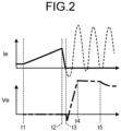
- FIG. 2 is a time chart for describing operation of the direct-current circuit breaker 1 according to the first embodiment.
- the upper diagram of FIG. 2 illustrates the waveform of a current Ie that flows through the interrupter 3 when an accident occurs; and the lower diagram of FIG. 2 illustrates the waveform of a voltage Ve that is applied to the interrupter 3 when the accident occurs.
- a broken line in the upper diagram of FIG. 2 indicates the waveform of resonance current.
- the control circuit 20 closes the activation switch 6.
- the activation switch 6 When the activation switch 6 is closed, the charge of the capacitor 5 is released from the capacitor 5 to a loop including the activation switch 6, the capacitor 5, the reactor 7, and the interrupter 3.
- a resonance current flows from the capacitor 5 through the reactor 7, the interrupter 3, and the activation switch 6.
- the direct-current circuit breaker 1 superimposes, on the accident current, an oscillating current flowing in a direction opposite to the direction of a direct current that is the accident current in the interrupter 3 (time t2).
- the current zero point is created by the superimposing of the oscillating current on the accident current (time t3) .
- the control circuit 20 opens the interrupter 3 to interrupt the current. In this way, extinction of arc, that is, current interruption is completed in the interrupter 3.
- the peak value of a resonance current Ig to be superimposed on the accident current can be calculated by equation (1).
- Ig ⁇ Cp / Lp ⁇ Vc
- the symbol “Cp” denotes the capacitance of the capacitor 5
- the symbol “Lp” denotes the reactance of the reactor 7
- the symbol “Vc” denotes the charging voltage of the capacitor 5.
- Each parameter of equation (1) is adjusted such that the peak value of LC resonance current is larger than the value of current to be interrupted.
- the lightning arrester 8 starts energy processing at time t4 at which the voltage Ve reaches a certain voltage value.
- the lightning arrester 8 suppresses an increase in the voltage Ve by performing energy processing from time t4 to time t5.
- the lightning arrester 8 processes energy remaining in the power system after the arc is extinguished by the interrupter 3.
- the charging voltage Vc of the capacitor 5 is detected by the voltage detection circuit 12.
- the voltage detection circuit 12 outputs the detected charging voltage Vc to the control circuit 20.
- the voltage detection circuit 12 includes the voltage dividing circuit including the resistor Z1 and the resistor Z2.
- the voltage detection circuit 12 detects a divided voltage of the resistor Z2, and inputs the divided voltage to the control circuit 20.
- the control circuit 20 obtains the charging voltage Vc of the capacitor 5 based on the divided voltage of the resistor Z2 and the respective resistance values of the resistor Z1 and the resistor Z2.
- the voltage detection circuit 12 may detect the charging voltage Vc by using a technique other than the voltage dividing circuit.
- FIG. 3 is a flowchart illustrating charging operation of the control circuit 20.
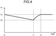
- FIG. 4 is a time chart illustrating a temporal change in the charging voltage Vc of the capacitor 5.
- the charging switch 10 is a switch that can interrupt current.
- the first voltage value Vu is, for example, a rated voltage of a module included in the direct-current circuit breaker 1, and functions as an upper limit for charging voltage control.
- the control circuit 20 closes the charging switch 10 (step S140).
- the second voltage value Vd is slightly smaller than the first voltage value Vu by a value ⁇ , and functions as a lower limit for charging voltage control.
- step S105 When the charging switch 10 is closed, the capacitor 5 is recharged, and the charging voltage Vc increases again (step S105). Operations of steps S105 to S140 are repeated until operation of the direct-current circuit breaker 1 is completed.
- the control circuit 20 keeps the charging voltage Vc within a range from the second voltage value Vd to the first voltage value Vu by performing such control.
- the first voltage value Vu is set to, for example, 80 kV
- the second voltage value Vd is set to a value slightly smaller than 80 kV by the value ⁇ .
- a period from time t0 to time t1 indicates a period of self-discharge due to floating impedance after completion of the charging of the capacitor 5.
- the charging switch 10 is in an open state.
- the charging switch 10 is closed.
- the capacitor 5 is recharged, and the charging voltage Vc increases again.
- the charging switch 10 is opened. This prevents the capacitor 5 from being discharged via the charging resistor 11.
- the charging switch 10 when the charging voltage Vc exceeds the first voltage value Vu, the charging switch 10 is opened, and when the charging voltage Vc falls below the second voltage value Vd, the charging switch 10 is closed, as described above. Therefore, the charging voltage Vc can be kept within the range from the second voltage value Vd to the first voltage value Vu. As a result, the charging resistor 11 can be downsized.
- FIG. 5 is a diagram illustrating a configuration of a direct-current circuit breaker system 30 according to a second embodiment.
- the direct-current circuit breaker system 30 according to the second embodiment includes a plurality of direct-current circuit breakers 1a, 1b, 1c, and 1d connected in series.
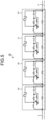
- FIG. 6 is a diagram illustrating a configuration of the direct-current circuit breaker 1a according to the second embodiment.
- the other direct-current circuit breakers 1b, 1c, and 1d also have the same configuration as the direct-current circuit breaker 1a.
- the left side of the direct-current line 2 in the drawing is connected to a converter (not illustrated) that converts an alternating-current system into a direct-current system. It is possible to apply the direct-current circuit breaker system 30 to a 320-kV power system by connecting the four direct-current circuit breakers 1a to 1d rated at 80 kV in series. That is, direct-current power of 320 kV is supplied from the converter (not illustrated) to the direct-current line 2.
- the direct-current circuit breaker 1a includes: the interrupter 3; the resonance circuit 4 including the capacitor 5, the activation switch 6, and the reactor 7; the lightning arrester 8; the charging circuit 9 including the charging switch 10 and a variable charging resistor 15; the voltage detection circuit 12; and a control circuit 25.
- the charging resistor 11 in FIG. 1 has been replaced with the variable charging resistor 15, and the control circuit 20 in FIG. 1 has been replaced with the control circuit 25. Operation and functions of other constituent elements are the same as those illustrated in FIG. 1 . Thus, redundant description will be omitted.
- the variable charging resistor 15 varies its resistance value under the control of the control circuit 25. Details thereof will be described below.
- the charging switch 10 in a closed state is opened, so that a charging current Ic flowing through the charging switch 10 is interrupted to stop the charging.
- the charging switch 10 is a switch that can interrupt current.
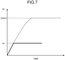
- FIG. 7 is a time chart illustrating a state of charging of the capacitor 5 of each of the direct-current circuit breakers 1a to 1d.
- the vertical axis represents the charging voltage Vc.
- the state of charging of the capacitor 5 is indicated by a solid line.
- the charging switch 10 is closed, the capacitor 5 is charged, and the charging voltage Vc increases.
- the charging voltage Vc reaches a fourth voltage value Vu that is the rated voltage
- the charging switch 10 is opened to stop the charging.
- the capacitor 5 is prevented from being overcharged to the system voltage of 320 kV as indicated by a broken line.
- FIG. 8 is a time chart for describing interruption of charging current of the capacitor of the direct-current circuit breaker in the second embodiment.
- FIG. 8 illustrates the relationship between the charging voltage Vc and the charging current Ic. As illustrated in FIG. 8 , the value of the charging current is still large at time t1 at which the charging voltage Vc reaches 80 kV which is the rated voltage.
- the resistance value of the variable charging resistor 15 is increased before completion of charging so as to reduce the charging current Ic to a level at which the charging switch 10 can effectively interrupt the charging current Ic.
- the charging voltage Vc reaches a third voltage value V1 that is slightly smaller than the fourth voltage value Vu, which is the rated voltage of 80 kV
- the resistance value of the variable charging resistor 15 is changed to a second resistance value larger than a first resistance value that is a resistance value of a steady state.
- current can be easily interrupted by the charging switch 10.
- FIG. 9 is a flowchart illustrating charging operation of the control circuit 25 of the second embodiment.
- operation of the control circuit 25 of the direct-current circuit breaker 1a will be described, but the control circuits 25 of the other direct-current circuit breakers 1b, 1c, and 1d also operate in the same manner.
- the control circuit 25 closes the charging switch 10 (step S200).
- the capacitor 5 is charged through a charging path indicated by arrows F in FIGS. 5 and 6 , so that the charging voltage Vc increases (step S205).
- the control circuit 25 monitors the charging voltage Vc obtained from a value detected by the voltage detection circuit 12.
- the control circuit 25 changes the resistance value of the variable charging resistor 15 from the first resistance value, which is the resistance value of a steady state, to the second resistance value larger than the first resistance value (step S220).
- the charging current Ic flowing through the charging switch 10 decreases.
- the control circuit 25 opens the charging switch 10 (step S240).
- the charging switch 10 When the charging switch 10 is opened, the charging current Ic is at the level at which the charging switch 10 can easily interrupt the charging current Ic, as a result of being reduced by the variable charging resistor 15. Thereafter, the charging switch 10 is in an open state. Therefore, the capacitor 5 is prevented from being discharged via the variable charging resistor 15 that is grounded.
- control circuit 25 performs control in such a way as to close the charging switch 10 when the charging voltage Vc falls below the second voltage value Vd, and to open the charging switch 10 when the charging voltage Vc exceeds the first voltage value Vu. Therefore, the charging voltage Vc can be kept within the range of the second voltage value Vd to the first voltage value Vu.
- the resistance value of the variable charging resistor 15 is changed to the second resistance value larger than the first resistance value, which is the resistance value of a steady state, before the charging of the capacitor 5 is completed in the direct-current circuit breaker system 30 in which the plurality of direct-current circuit breakers 1a to 1d is connected in series.
- the charging switch 10 As described above, in the second embodiment, the resistance value of the variable charging resistor 15 is changed to the second resistance value larger than the first resistance value, which is the resistance value of a steady state, before the charging of the capacitor 5 is completed in the direct-current circuit breaker system 30 in which the plurality of direct-current circuit breakers 1a to 1d is connected in series.
- each of the direct-current circuit breakers 1a to 1d stops charging the capacitor 5 at the rated voltage of a module included in each of the direct-current circuit breakers 1a to 1d, so that the capacitor 5 is prevented from being overcharged to the system voltage.
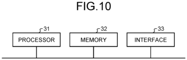
- FIG. 10 is a diagram showing an example of a hardware configuration of the control circuit 20 included in the direct-current circuit breaker 1 according to the first embodiment, or the control circuit 25 included in each of the direct-current circuit breakers 1a to 1d according to the second embodiment.
- FIG. 10 illustrates a hardware configuration to be adopted when the functions of the control circuits 20 and 25 are implemented by use of hardware that executes programs.
- a processor 31, a memory 32, and an interface 33 are connected to each other via a bus.
- the processor 31 is a central processing unit (CPU), a processing device, an arithmetic device, a microprocessor, a microcomputer, or a digital signal processor (DSP). Each function of the control circuits 20 and 25 is implemented by the processor 31, and software, firmware, or a combination of software and firmware.
- the software or firmware is written as a program, and stored in the memory 32 that is a built-in memory.
- the memory 32 is a nonvolatile or volatile semiconductor memory. Examples of the memory 32 include a random access memory (RAM), a read only memory (ROM), a flash memory, an erasable programmable read only memory (EPROM), and an electrically erasable programmable read only memory (EEPROM) (registered trademark).
- the interface 33 plays a role as signal input and signal output.
- the interface 33 outputs a command to each of the interrupter 3, the activation switch 6, and the charging switch 10.
- a signal indicating a result of detection performed by the voltage detection circuit 12 is input to the interface 33.
Landscapes
- Engineering & Computer Science (AREA)
- Power Engineering (AREA)
- Driving Mechanisms And Operating Circuits Of Arc-Extinguishing High-Tension Switches (AREA)
Applications Claiming Priority (1)
| Application Number | Priority Date | Filing Date | Title |
|---|---|---|---|
| PCT/JP2020/045906 WO2022123700A1 (fr) | 2020-12-09 | 2020-12-09 | Disjoncteur à courant continu et système de disjoncteur à courant continu |
Publications (3)
| Publication Number | Publication Date |
|---|---|
| EP4261865A1 true EP4261865A1 (fr) | 2023-10-18 |
| EP4261865A4 EP4261865A4 (fr) | 2024-03-06 |
| EP4261865B1 EP4261865B1 (fr) | 2026-03-25 |
Family
ID=77269602
Family Applications (1)
| Application Number | Title | Priority Date | Filing Date |
|---|---|---|---|
| EP20965083.7A Active EP4261865B1 (fr) | 2020-12-09 | 2020-12-09 | Disjoncteur à courant continu et système de disjoncteur à courant continu |
Country Status (4)
| Country | Link |
|---|---|
| US (1) | US12243697B2 (fr) |
| EP (1) | EP4261865B1 (fr) |
| JP (1) | JP6921364B1 (fr) |
| WO (1) | WO2022123700A1 (fr) |
Cited By (2)
| Publication number | Priority date | Publication date | Assignee | Title |
|---|---|---|---|---|
| EP4506976A1 (fr) * | 2023-08-11 | 2025-02-12 | Schneider Electric Industries Sas | Dispositif de coupure de courant pour interrompre un trajet de courant continu haute tension |
| EP4506977A1 (fr) * | 2023-08-11 | 2025-02-12 | Schneider Electric Industries Sas | Appareil de coupure de courant pour trajet de courant continu haute tension |
Families Citing this family (4)
| Publication number | Priority date | Publication date | Assignee | Title |
|---|---|---|---|---|
| WO2020039580A1 (fr) * | 2018-08-24 | 2020-02-27 | 三菱電機株式会社 | Dispositif disjoncteur à courant continu |
| WO2023047556A1 (fr) * | 2021-09-27 | 2023-03-30 | 三菱電機株式会社 | Disjoncteur de courant continu |
| US12437942B2 (en) * | 2022-10-07 | 2025-10-07 | Board Of Supervisors Of Louisiana State University And Agricultural And Mechanical College | Bipolar hybrid circuit breaker for low-voltage DC circuits |
| US12438360B2 (en) * | 2022-10-07 | 2025-10-07 | Board Of Supervisors Of Louisiana State University And Agricultural And Mechanical College | Bipolar hybrid circuit breaker for low-voltage dc circuits |
Family Cites Families (12)
| Publication number | Priority date | Publication date | Assignee | Title |
|---|---|---|---|---|
| JPS59169008A (ja) * | 1983-03-16 | 1984-09-22 | 株式会社日立製作所 | 直流しや断器の制御方法 |
| US4740858A (en) * | 1985-08-06 | 1988-04-26 | Mitsubishi Denki Kabushiki Kaisha | Zero-current arc-suppression dc circuit breaker |
| WO2011141055A1 (fr) * | 2010-05-11 | 2011-11-17 | Abb Technology Ag | Appareil disjoncteur pour courant continu sous haute tension |
| EP2523204B1 (fr) * | 2011-05-12 | 2019-09-04 | ABB Schweiz AG | Agencement de circuit et procédé pour l'interruption d'un flux de courant dans un accès de courant CC |
| EP2523205B1 (fr) * | 2011-05-12 | 2017-04-26 | ABB Schweiz AG | Circuit et procédé pour l'interruption d'un flux de courant dans un accès de courant CC |
| WO2013131581A1 (fr) * | 2012-03-09 | 2013-09-12 | Siemens Aktiengesellschaft | Dispositif de commutation d'un courant continu dans un pôle d'un réseau de tension continue |
| WO2013164874A1 (fr) | 2012-05-01 | 2013-11-07 | 三菱電機株式会社 | Coupe-circuit cc |
| US9530588B2 (en) * | 2013-03-27 | 2016-12-27 | Abb Technology Ltd | Circuit breaking arrangement |
| KR20150078491A (ko) * | 2013-12-30 | 2015-07-08 | 주식회사 효성 | 고전압 dc 차단기 |
| JP6042035B2 (ja) * | 2014-05-01 | 2016-12-14 | 三菱電機株式会社 | 直流遮断装置 |
| WO2020039580A1 (fr) | 2018-08-24 | 2020-02-27 | 三菱電機株式会社 | Dispositif disjoncteur à courant continu |
| EP3896714B1 (fr) | 2018-12-10 | 2024-03-13 | Mitsubishi Electric Corporation | Disjoncteur à courant continu |
-
2020
- 2020-12-09 JP JP2021517072A patent/JP6921364B1/ja active Active
- 2020-12-09 WO PCT/JP2020/045906 patent/WO2022123700A1/fr not_active Ceased
- 2020-12-09 US US18/247,304 patent/US12243697B2/en active Active
- 2020-12-09 EP EP20965083.7A patent/EP4261865B1/fr active Active
Cited By (2)
| Publication number | Priority date | Publication date | Assignee | Title |
|---|---|---|---|---|
| EP4506976A1 (fr) * | 2023-08-11 | 2025-02-12 | Schneider Electric Industries Sas | Dispositif de coupure de courant pour interrompre un trajet de courant continu haute tension |
| EP4506977A1 (fr) * | 2023-08-11 | 2025-02-12 | Schneider Electric Industries Sas | Appareil de coupure de courant pour trajet de courant continu haute tension |
Also Published As
| Publication number | Publication date |
|---|---|
| US20230411091A1 (en) | 2023-12-21 |
| EP4261865A4 (fr) | 2024-03-06 |
| EP4261865B1 (fr) | 2026-03-25 |
| US12243697B2 (en) | 2025-03-04 |
| JPWO2022123700A1 (fr) | 2022-06-16 |
| WO2022123700A1 (fr) | 2022-06-16 |
| JP6921364B1 (ja) | 2021-08-18 |
Similar Documents
| Publication | Publication Date | Title |
|---|---|---|
| EP4261865B1 (fr) | Disjoncteur à courant continu et système de disjoncteur à courant continu | |
| US10020650B2 (en) | Battery energy storage system with arc flash protection, energy conversion system and protection method | |
| US9875861B2 (en) | Device and method for switching a direct current | |
| US8995097B2 (en) | High voltage DC breaker apparatus | |
| EP3413330B1 (fr) | Disjoncteur à courant continu | |
| CN106560968A (zh) | 二次电池保护集成电路、二次电池保护装置及电池组 | |
| EP3664116B1 (fr) | Disjoncteur | |
| KR20180031057A (ko) | 과전압 과전류 보호회로 및 이동단말 | |
| KR20080018825A (ko) | 충방전 제어 회로 및 배터리 장치 | |
| EP4160640B1 (fr) | Disjoncteur à courant continu | |
| JP2003259546A (ja) | 二次電池用充放電保護回路 | |
| EP3168961A1 (fr) | Dispositif de source d'alimentation sans coupure | |
| CN1988315A (zh) | 电池装置 | |
| US12237125B2 (en) | Method for coordinating protective devices in a distribution grid | |
| JP2001112182A (ja) | 二次電池の保護回路 | |
| JP6155854B2 (ja) | 電池システム | |
| CN110870154B (zh) | 电力转换装置、电力系统以及电力系统的无效电力抑制方法 | |
| JP2007074884A (ja) | コンバータ装置(低電圧検出方法) | |
| CN107611929A (zh) | 一种高阻抗变压器旁路开关失灵判断和解决方法 | |
| EP4411772B1 (fr) | Disjoncteur de courant continu | |
| KR100962497B1 (ko) | 지연회로를 이용한 배터리팩의 2차 보호회로 안정화 장치 | |
| EP2569794B1 (fr) | Disjoncteur haute tension à courant continu | |
| HK1024345A1 (en) | Charging and discharging control circuit and charging type power supply device | |
| HK1024345B (en) | Charging and discharging control circuit and charging type power supply device | |
| JPH05326106A (ja) | 直流避雷器 |
Legal Events
| Date | Code | Title | Description |
|---|---|---|---|
| STAA | Information on the status of an ep patent application or granted ep patent |
Free format text: STATUS: THE INTERNATIONAL PUBLICATION HAS BEEN MADE |
|
| PUAI | Public reference made under article 153(3) epc to a published international application that has entered the european phase |
Free format text: ORIGINAL CODE: 0009012 |
|
| STAA | Information on the status of an ep patent application or granted ep patent |
Free format text: STATUS: REQUEST FOR EXAMINATION WAS MADE |
|
| 17P | Request for examination filed |
Effective date: 20230509 |
|
| AK | Designated contracting states |
Kind code of ref document: A1 Designated state(s): AL AT BE BG CH CY CZ DE DK EE ES FI FR GB GR HR HU IE IS IT LI LT LU LV MC MK MT NL NO PL PT RO RS SE SI SK SM TR |
|
| A4 | Supplementary search report drawn up and despatched |
Effective date: 20240206 |
|
| RIC1 | Information provided on ipc code assigned before grant |
Ipc: H02H 9/02 20060101ALI20240131BHEP Ipc: H02H 3/087 20060101ALI20240131BHEP Ipc: H01H 33/59 20060101AFI20240131BHEP |
|
| DAV | Request for validation of the european patent (deleted) | ||
| DAX | Request for extension of the european patent (deleted) | ||
| GRAP | Despatch of communication of intention to grant a patent |
Free format text: ORIGINAL CODE: EPIDOSNIGR1 |
|
| STAA | Information on the status of an ep patent application or granted ep patent |
Free format text: STATUS: GRANT OF PATENT IS INTENDED |
|
| INTG | Intention to grant announced |
Effective date: 20250911 |
|
| GRAS | Grant fee paid |
Free format text: ORIGINAL CODE: EPIDOSNIGR3 |
|
| GRAJ | Information related to disapproval of communication of intention to grant by the applicant or resumption of examination proceedings by the epo deleted |
Free format text: ORIGINAL CODE: EPIDOSDIGR1 |
|
| GRAL | Information related to payment of fee for publishing/printing deleted |
Free format text: ORIGINAL CODE: EPIDOSDIGR3 |
|
| STAA | Information on the status of an ep patent application or granted ep patent |
Free format text: STATUS: REQUEST FOR EXAMINATION WAS MADE |
|
| GRAP | Despatch of communication of intention to grant a patent |
Free format text: ORIGINAL CODE: EPIDOSNIGR1 |
|
| STAA | Information on the status of an ep patent application or granted ep patent |
Free format text: STATUS: GRANT OF PATENT IS INTENDED |
|
| INTC | Intention to grant announced (deleted) | ||
| GRAA | (expected) grant |
Free format text: ORIGINAL CODE: 0009210 |
|
| STAA | Information on the status of an ep patent application or granted ep patent |
Free format text: STATUS: THE PATENT HAS BEEN GRANTED |
|
| INTG | Intention to grant announced |
Effective date: 20260204 |
|
| AK | Designated contracting states |
Kind code of ref document: B1 Designated state(s): AL AT BE BG CH CY CZ DE DK EE ES FI FR GB GR HR HU IE IS IT LI LT LU LV MC MK MT NL NO PL PT RO RS SE SI SK SM TR |
|
| REG | Reference to a national code |
Ref country code: CH Ref legal event code: F10 Free format text: ST27 STATUS EVENT CODE: U-0-0-F10-F00 (AS PROVIDED BY THE NATIONAL OFFICE) Effective date: 20260325 Ref country code: GB Ref legal event code: FG4D |
|
| REG | Reference to a national code |
Ref country code: CH Ref legal event code: R17 Free format text: ST27 STATUS EVENT CODE: U-0-0-R10-R17 (AS PROVIDED BY THE NATIONAL OFFICE) Effective date: 20260327 |
|
| REG | Reference to a national code |
Ref country code: DE Ref legal event code: R096 Ref document number: 602020069429 Country of ref document: DE |
|
| REG | Reference to a national code |
Ref country code: IE Ref legal event code: FG4D |