EP4261962A1 - Procédé de fabrication d'électrode à membrane - Google Patents
Procédé de fabrication d'électrode à membrane Download PDFInfo
- Publication number
- EP4261962A1 EP4261962A1 EP20964504.3A EP20964504A EP4261962A1 EP 4261962 A1 EP4261962 A1 EP 4261962A1 EP 20964504 A EP20964504 A EP 20964504A EP 4261962 A1 EP4261962 A1 EP 4261962A1
- Authority
- EP
- European Patent Office
- Prior art keywords
- strip
- frame
- layer
- ccm
- station
- Prior art date
- Legal status (The legal status is an assumption and is not a legal conclusion. Google has not performed a legal analysis and makes no representation as to the accuracy of the status listed.)
- Pending
Links
Images







Classifications
-
- H—ELECTRICITY
- H01—ELECTRIC ELEMENTS
- H01M—PROCESSES OR MEANS, e.g. BATTERIES, FOR THE DIRECT CONVERSION OF CHEMICAL ENERGY INTO ELECTRICAL ENERGY
- H01M8/00—Fuel cells; Manufacture thereof
- H01M8/10—Fuel cells with solid electrolytes
- H01M8/1004—Fuel cells with solid electrolytes characterised by membrane-electrode assemblies [MEA]
-
- H—ELECTRICITY
- H01—ELECTRIC ELEMENTS
- H01M—PROCESSES OR MEANS, e.g. BATTERIES, FOR THE DIRECT CONVERSION OF CHEMICAL ENERGY INTO ELECTRICAL ENERGY
- H01M8/00—Fuel cells; Manufacture thereof
- H01M8/10—Fuel cells with solid electrolytes
- H01M2008/1095—Fuel cells with polymeric electrolytes
-
- Y—GENERAL TAGGING OF NEW TECHNOLOGICAL DEVELOPMENTS; GENERAL TAGGING OF CROSS-SECTIONAL TECHNOLOGIES SPANNING OVER SEVERAL SECTIONS OF THE IPC; TECHNICAL SUBJECTS COVERED BY FORMER USPC CROSS-REFERENCE ART COLLECTIONS [XRACs] AND DIGESTS
- Y02—TECHNOLOGIES OR APPLICATIONS FOR MITIGATION OR ADAPTATION AGAINST CLIMATE CHANGE
- Y02E—REDUCTION OF GREENHOUSE GAS [GHG] EMISSIONS, RELATED TO ENERGY GENERATION, TRANSMISSION OR DISTRIBUTION
- Y02E60/00—Enabling technologies; Technologies with a potential or indirect contribution to GHG emissions mitigation
- Y02E60/30—Hydrogen technology
- Y02E60/50—Fuel cells
-
- Y—GENERAL TAGGING OF NEW TECHNOLOGICAL DEVELOPMENTS; GENERAL TAGGING OF CROSS-SECTIONAL TECHNOLOGIES SPANNING OVER SEVERAL SECTIONS OF THE IPC; TECHNICAL SUBJECTS COVERED BY FORMER USPC CROSS-REFERENCE ART COLLECTIONS [XRACs] AND DIGESTS
- Y02—TECHNOLOGIES OR APPLICATIONS FOR MITIGATION OR ADAPTATION AGAINST CLIMATE CHANGE
- Y02P—CLIMATE CHANGE MITIGATION TECHNOLOGIES IN THE PRODUCTION OR PROCESSING OF GOODS
- Y02P70/00—Climate change mitigation technologies in the production process for final industrial or consumer products
- Y02P70/50—Manufacturing or production processes characterised by the final manufactured product
Definitions
- the disclosure relates to the technical field of fuel cells, in particular to a method for manufacturing a membrane electrode.
- Membrane electrode (MEA, Membrane Electrode Assemblies) is composed of CCM (Catalyst Coated Membrane), cathode and anode frame, cathode and anode GDL (gas diffusion layer).
- CCM Catalyst Coated Membrane
- GDL gas diffusion layer
- a traditional manufacturing method adopts the production process of combined sheets, that is, to make the CCM, frame and GDL into sheets by sheet-making technology, and then assemble the frame and CCM into a combined sheet by flat laminating, and then bond the cathode GDL and anode GDL respectively on opposite sides of the combined sheet, thereby obtaining an end product of the membrane electrode.
- the production process of combining sheets is low in production efficiency, and cannot meet the production capacity demand.
- a method for manufacturing a membrane electrode including:
- the embodiment further includes:
- the first frame strip is provided with a first positioning hole
- the second frame strip is provided with a second positioning hole
- the embodiment further includes:
- the embodiment further includes: removing the second bottom supporting membrane layer of the second frame strip, and removing the first bottom supporting membrane layer of the first frame strip.
- the embodiment further includes: at a heat-laminating station downstream of the cutting station, heat-laminating the second combined strip to activate the first bonding adhesive layer and the second bonding adhesive layer.
- the embodiment further includes:
- the embodiment before the step of "unwinding and outputting a first frame strip passing through the first laminating station", the embodiment further includes:
- the embodiment further includes: the first frame strip passing through an electrostatic generator, so that the regions without the first adhesive between the first frame layer and the first bottom supporting membrane layer are electrostatically adsorbed to each other.
- the embodiment further includes:
- the embodiment before the step "unwinding and outputting a second frame strip passing through the second laminating station", the embodiment further includes:
- the embodiment further includes: the second frame strip passing through the electrostatic generator, so that the regions without the second adhesive between the second frame layer and the second bottom supporting membrane layer are electrostatically adsorbed to each other.
- the embodiment further includes:
- the embodiment before the step "unwinding and outputting a CCM strip 5 passing through the first laminating station", the embodiment further includes:
- the embodiment before the step "unwinding and outputting the pre-processed CCM strip passing through the cutting station", the embodiment further includes:
- the first bonding adhesive layer on the first frame strip is activated by heating and laminating the first frame strip and the CCM strip that are unwound and outputted to the first laminating station; in addition, the CCM units of the CCM strip are bonded one by one on the first active region of the first frame layer during laminating, and are separated from the backing membrane, that is to realize transferring of the CCM units of the CCM strip to the first active region of the first frame layer.
- the present disclosure adopts a roll-to-toll method to realize the transfer of CCM units to the first active region of the first frame layer, thereby facilitating improvement of production efficiency and commendably satisfying capacity demands.
- first and second are used for descriptive purposes only, and cannot be interpreted as indicating or implying relative importance or implicitly specifying the quantity of indicated technical features.
- the features defined as “first” and “second” may explicitly or implicitly include at least one of these features.
- “plurality” means at least two, such as two, three, etc., unless specifically defined otherwise.
- the first feature may be in direct contact with the first feature or the first and second feature may be in direct contact with the second feature through an intermediary, touch.
- “above”, “over” and “on” the first feature on the second feature may mean that the first feature is directly above or obliquely above the second feature, or simply means that the first feature is higher in level than the second feature.
- “Below”, “beneath” and “under” the first feature may mean that the first feature is directly below or obliquely below the second feature, or simply means that the first feature is horizontally lower than the second feature.
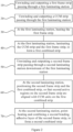
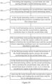
- a method for manufacturing a membrane electrode includes the following steps: S10, unwinding and outputting a first frame strip 3 passing through a first laminating station a7.
- the first frame strip 3 includes a first bottom supporting membrane layer 11 and a first frame layer 21 stacked on the first bottom supporting membrane layer 11.
- the side of the first frame layer 21 away from the first bottom supporting membrane layer 11 is coated with a first bonding adhesive layer, and the first frame layer 21 has a plurality of first active regions 212, and the plurality of first active regions 212 are arranged sequentially along the length direction of the first frame strip 3 at intervals.
- the first bonding adhesive layer may be hot melt adhesive.
- first bonding adhesive layer is located on one side of the first frame layer 21 away from the first bottom supporting membrane layer 11, and can be coated in a way of covering the entire surface.
- a plurality of first active regions 212 are located in the middle of the first frame layer 21 and arranged at intervals along the length direction of the first frame strip 3.
- the CCM strip 5 includes a backing membrane 51 and a plurality of CCM units 52 stacked on the backing membrane 51, and the plurality of CCM units 52 are arranged at intervals along the length direction of the CCM strip 5.
- the CCM units 52 includes a PEM membrane 521 (i.e., a proton exchange membrane) coated with catalytic layers 522 on two opposite sides of the PEM membrane (see Fig. 4 ).
- the CCM units 52 are attached to the first active region 212 of the first frame layer 21 one by one through the first bonding adhesive layer activated by heating, and are separated from the backing membrane 51.
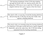
- step S40 specifically includes the following steps: S41, the backing membrane 51 of the CCM strip 5 winding through the pinch roller set 32, and the pinch roller set 32 pulling the CCM strip 5 to move until the CCM units 52 are aligned with the first active region 212 of the first frame strip 3.
- the pinch roller set 32 returning along the heating platform 31 to bond the CCM units 52 on the first active region 212 aligned therewith, and at the same time, the CCM units 52 being separated from the backing membrane 51.
- the CCM strip 5 is pulled until the CCM units 52 are aligned with the first active region 212 of the first frame strip 3 by using the horizontal movement of the pinch roller set 32.
- the vertical movement of the pinch roller set 32 is used for pressing the CCM strip 5 and the first frame strip 3 against the heating platform 31.
- the pinch roller set 32 rolls in the opposite direction along the heating platform 31 (that is, opposite to the direction of the horizontal movement of the previous pulling of the CCM strip 5), and the backing membrane 51 wound through the pinch roller set 32 is wound up, thereby realizing bonding of the CCM units 52 on the first active region 212 aligned therewith, and realizing separation of the CCM units 52 from the backing membrane 51.
- the pinch roller set 32 includes two pinch rollers, and the backing membrane 51 winds through the two pinch rollers in an S-shape, so that the two pinch rollers can pull the CCM strip 5 to move when they are moving in the horizontal direction.
- Steps S10 and S20 can be performed simultaneously, i.e., to unwinding and outputting the first frame strip 3 and the CCM strip 5 at the same time.
- Steps S30 and S40 can also be performed simultaneously (heating and laminating at the same time). Alternatively, Step S30 is performed first, and then step S40 is performed (heating first and then laminating).
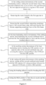
- the embodiment of the present disclosure may also include the following steps: S50, unwinding and outputting a second frame strip 8 passing through the second laminating station a8 downstream of the first laminating station a7.
- the second frame strip 8 includes a second bottom supporting membrane layer and a second frame layer stacked on the second bottom supporting membrane layer.
- One side of the second frame layer away from the second bottom supporting membrane layer is coated with a second bonding adhesive layer, and the second frame layer has a plurality of second active regions sequentially arranged at intervals along the length direction of the second frame strip 8.
- the membrane layer structure of the second frame strip 8 may be the same as that of the first frame strip 3.
- the second bonding adhesive layer can be hot melt adhesive.
- the second bonding adhesive layer is located on the side of the second frame layer away from the second bottom supporting membrane layer, and can be coated in a way of covering the entire surface.
- a plurality of second active regions are located in the middle of the second frame layer and are arranged at intervals along the length direction of the second frame strip 8.
- the second active regions of the second frame layer of the second frame strip 8 are combined with the CCM units 52 on the first combined strip 7 in a roll-to-roll manner, which is conducive to improving production efficiency and commendably meet capacity needs.
- the pre-fixation between the second frame strip 8 and the first combined strip 7 is realized by means of point heating, thereby avoiding deviation between the CCM units 52 and the second active regions during subsequent transportation, which is beneficial to improving product quality.
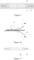
- the heating points d during point heating combining is arranged around the second active region of the second strip 8 (see FIG. 8 ), so as to facilitate subsequent packaging of the CCM units 52.
- the first frame strip 3 is provided with a first positioning hole a.
- the second frame strip 8 is provided with a second positioning hole.
- Step S60 specifically includes: inserting the positioning pins correspondingly into the first positioning hole a and the second positioning hole at the second laminating station a8, that is, the positioning pins position the second frame strip 8 and the first combined strip 7, so that the second active regions of the second frame strip 8 is aligned with the CCM units 52 on the first combined strip 7.
- the embodiment specifically includes the following steps: S71, at the cutting station a12 downstream of the second laminating station a8, cutting the second frame strip 8 of the second combined strip 9, so as to form a first gap f between two adjacent active regions of the second frame strip 8.
- waste disposal can of course be performed during cutting, which is not limited here.
- the deformation of the second frame strip 8 can be released, thereby reducing positional error of the active regions of the second frame strip 8 and facilitating improvement of product quality.
- the embodiment also includes: S73, removing the second bottom supporting membrane layer of the second frame strip 8, and removing the first bottom supporting membrane layer 11 of the first frame strip 3. More specifically, a waste disposal belt and the second composite strip 9 are unwound and output, both pass between the two paired rollers and are squeezed by the two paired rollers, thereby bonding the second bottom supporting layer (which is discontinuous) of the second frame strip 8. At the same time, the first bottom supporting membrane layer 11 of the first frame strip 3 is connected to the winding device, and the first bottom supporting membrane layer 11 of the first frame strip 3 in the second combined strip 9 passed between the two paired rollers is wound up by the winding device.
- the embodiment also includes the following steps: S74, at a heat-laminating station a10 (see FIG. 1 ) downstream of the cutting station a12 (see FIG. 1 ), heat-laminating the second combined strip 9 to activate the first bonding adhesive layer and the second bonding adhesive layer.
- S74 at a heat-laminating station a10 (see FIG. 1 ) downstream of the cutting station a12 (see FIG. 1 ), heat-laminating the second combined strip 9 to activate the first bonding adhesive layer and the second bonding adhesive layer.
- the CCM units 52 are sealed and attached to the first active regions 212 and the second active regions, thereby realizing packaging, that is, to complete the five-in-one process, and to seal the first frame layer 21, the CCM units 52 and the second frame layer, together they forming the second combined strip 9.
- the embodiment further includes the following steps: S75, at the patching station a13 (see FIG. 1 ) downstream of the heat-laminating station a10, bonding the GDL patches 611 on two opposite sides of the second combined strip 9, and covering regions corresponding to the CCM units 52 (that is, the first active region and the second active region) with the GDL patches 611. Specifically, when the GDL patches 611 is being bonded, detect the position of the GDL patches 611 via a visual detection unit, so as to improve bonding precision of the GDL patches 611.
- the embodiment further includes the following steps: S77, curing the bonding adhesive used for bonding the GDL patches 611. Specifically, when a pressure-sensitive adhesive is used as the bonding adhesive, the MEA product is laminated by a pressing plate to cure the pressure-sensitive adhesive. When a thermosetting adhesive is used as the bonding adhesive, the MEA product is heat-laminated with a heat-laminating device to cure the thermosetting adhesive.
- step S77 S78, cutting the MEA product to form the air nozzle and the outer contour.
- the MEA product can be cut using a die-cutting process.
- the embodiment of the present disclosure also include steps: S101, unwinding and outputting the first frame raw strip 2 passing through the third laminating station a1.
- the first frame raw strip 2 includes a first frame layer 21 (see FIG. 15 ) and a first release layer 22 (see FIG. 15 ), the first release layer 22 being stacked on one side of the first frame layer 21 having the first bonding adhesive layer, and the first release layer 22 is used to protect the first bonding adhesive layer.
- the first frame raw strip 2 may use a high temperature resistant membrane material such as PEN (polyethylene naphthalate).
- the first bottom supporting raw strip 1 includes a first bottom supporting membrane layer 11 (see FIG. 14 ) and a first protective membrane layer 13 (see FIG. 14 ) stacked on one side of the first bottom supporting membrane layer 11, the one side of the first bottom supporting membrane layer 11 facing the first protective membrane layer having a first adhesive 12;
- the first adhesive 12 is located on both sides of the first bottom supporting membrane layer 11 in its width direction, and extends lengthwise along the length direction of the first bottom supporting raw strip 1.
- the first bottom supporting raw strip 1 may be made of insulating and temperature-resistant materials such as PET (polyethylene terephthalate).
- step S104 laminating the first frame layer 21 and the first bottom supporting membrane layer 11 to form the first frame strip 3 (see FIG. 16 ).
- the first bottom supporting membrane layer 11 is attached to the side of the first frame layer 21 away from the first bonding adhesive layer through the first adhesive 12.
- the first frame raw strip 2 and the first bottom supporting raw strip 1 are combined in a roll-to-roll manner to form the first frame strip 3.
- the first frame layer 21 of the first frame raw strip 2 and the first bottom supporting membrane layer 11 of the first bottom supporting raw strip 1 can be laminated by using two pinch rollers. It is to be noted that step S101 and step S102 may be performed simultaneously.
- step S104 the following steps may be included: S105, the first frame strip 3 passing through an electrostatic generator b, so that the regions without the first adhesive 12 between the first frame layer 21 and the first bottom supporting membrane layer 11 are electrostatically adsorbed to each other.
- the first adhesive 12 is located on both sides of the first bottom supporting membrane layer 11 in the width direction, so that the two sides of the first frame layer 21 in the width direction are bonded to the first bottom supporting layer 11 by the first adhesive 12, the middle part in the width direction of the first frame layer 21 is electrostatically adsorbed to the first bottom supporting membrane layer 11, so that the entire surface of the first frame layer 21 is attached to the first bottom supporting membrane layer 11.
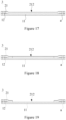
- step S105 At the first processing station a2 located downstream of the third laminating station a1, process the first positioning hole a (see FIG. 17 ) on the first frame strip 3, so as to facilitate positioning the first frame strip 3 using the first positioning hole a in subsequent processes, which is beneficial to improving process precision and product quality.
- step S107 At the second processing station a3 located downstream of the first processing station a2, using the first positioning hole a to position the first frame strip 3, and cutting the first frame layer 21 to hollow it out, so as to form the above-mentioned first active region 212 (See Fig. 18 ) in the hollowed-out region. Since in step S105, the regions without the first adhesive 12 between the first frame layer 21 and the first bottom supporting membrane layer 11 are electrostatically adsorbed to each other, therefore, the waste materials formed in the first active region 212 (that is, the hollowed-out area) after cutting are still electrostatically adsorbed on the first bottom supporting membrane layer 11.
- the first adhesive 12 is located on both sides of the first bottom supporting membrane layer 11 in the width direction, so that two sides of the first frame layer 21 in the width direction are bonded to the first bottom supporting membrane layer 11 by the first adhesive 12, and the middle part in the width direction of the first frame layer 21 is cut to be hollowed out (the first frame layer 21 is not cut-off at this time, and the two sides in the width direction remain continuous), the hollowed-out region is the above-mentioned first active region 212, the waste material formed in the first active region 212 due to cutting continues to be electrostatically adsorbed to the first bottom supporting membrane layer 11.
- step S50 unwinding and outputting a second frame raw strip passing through the fourth laminating station.
- the second frame raw strip includes a second frame layer and a second release layer, the second release layer is stacked on the side of the second frame layer with the second bonding adhesive layer, and the second release layer is used for protecting the second bonding adhesive layer.
- the second frame raw strip may use high temperature resistant membrane materials such as PEN (polyethylene naphthalate).
- the second bottom supporting raw strip includes a second bottom supporting membrane layer and a second protective membrane layer stacked on one side of the second bottom supporting membrane layer, the side of the second bottom supporting membrane layer facing the second protective membrane layer having the second adhesive, and the second protective membrane layer being used for protecting the second adhesive.
- the second adhesive is located on both sides of the second bottom supporting membrane layer in its width direction, and extends lengthwise along the length direction of the second bottom supporting raw strip.
- the second bottom supporting raw strip may use insulating and temperature-resistant materials such as PET (polyethylene terephthalate).
- Step S504 at the fourth laminating station, laminating the second frame layer and the second bottom supporting membrane layer to form the second frame strip 8.
- the second bottom supporting membrane layer is attached to one side of the second frame layer away from the second bonding adhesive layer via the second adhesive.
- the second frame raw strip and the second bottom supporting raw strip are combined in a roll-to-roll manner to form the second frame strip 8.
- two pinch rollers may be used to laminate the second frame layer of the second frame raw strip and the second bottom supporting membrane layer of the second bottom supporting raw strip. It is to be noted that Step S501 and Step S502 can be performed simultaneously.
- step S504 the following steps may be included: S505, the second frame strip 8 passing through the electrostatic generator, so that the regions without the second adhesive between the second frame layer and the second bottom supporting membrane layer are electrostatically adsorbed to each other.
- the second adhesive is located on both sides of the second bottom supporting membrane layer in the width direction, so that the two sides of the second frame layer in the width direction are bonded to the second bottom supporting membrane layer by the second adhesive, and the middle part of the width direction of the second frame layer is electrostatically adsorbed to the second bottom supporting membrane layer, so that the entire surface of the second frame layer is attached to the second bottom supporting membrane layer.
- step S505: S506. At the third processing station located downstream of the fourth laminating station, process the second positioning hole on the second frame strip 8, so that the second positioning hole can be used to performing positioning of the second frame strip 8 in subsequent processes, which is conducive to improving process precision and product quality.
- step S507 At the fourth processing station located downstream of the third processing station, use the second positioning hole to position the second frame strip 8, and cut the second frame layer to hollow it out, so as to form the above-mentioned second active region in the hollowed-out region. Since in step S505, the area outside the second adhesive between the second frame layer and the second bottom supporting membrane layer are electrostatically adsorbed to each other, the waste formed in the second active region (that is, the hollowed-out region) after cutting is still electrostatically adsorbed on the second bottom supporting membrane layer. Moreover, using the second positioning holes to position the second frame strip 8 is beneficial to improving the cutting precision of the second active region and improving product quality.
- the second adhesive is located on two sides in the width direction of the second bottom supporting membrane layer, so that the two sides in the width direction of the second frame layer are bonded to the second support by the second adhesive.
- the middle part in the width direction of the second frame layer is cut to be hollowed out (the second frame layer is not cut off at this time, and the two sides in the width direction remain continuous), and the hollowed-out region is the above-mentioned second active region, the waste material formed by cutting in the second active region continues to be electrostatically adsorbed on the second bottom supporting membrane layer.
- the embodiment of the present disclosure further includes the following steps: S201. Unwinding and outputting the pre-processed CCM strip passing through the cutting station a11.
- the pre-processed CCM strip includes the backing membrane 51 and a CCM layer stacked on one side of the backing membrane 51.
- the CCM layer includes a PEM membrane 521 (i.e., a proton exchange membrane) and catalytic layers 522 on opposite sides of the PEM membrane 521, and the PEM membrane 521 is a continuous membrane material.
- step S201 the following steps may be included: S2011, unwinding and outputting the CCM raw strip 4 passing through a slitting station a4 (see Figure 22 ).
- the CCM raw strip 4 includes a backing membrane 51 and a CCM layer stacked on the backing membrane.
- the membrane layer structure of the CCM raw strip 4 and the pre-processed CCM strip may be the same, except for the different dimensions in the width direction.
- the CCM raw strip 4 can be a zebra-coated CCM strip, which may be multi-row zebra-coated or single-row zebra-coated.
- the CCM raw strip 4 may also be a fully coated strip with CCM strips, which is not limited here.
- the PEM membrane 521 of the CCM layer of the CCM raw strip 4 is coated with at least two rows of catalytic layers 522, and each row of catalytic layers 522 is arranged at intervals along the width direction of the CCM raw strip 4.
- the CCM raw strip 4 is slitted along its width direction to obtain a plurality of pre-processing CCM strips, and each pre-processing CCM strip has one row of catalytic layer 522 on the PEM membrane 521 of the CCM layer.
- step S74 steps are also included before step S74: S741, unwinding and outputting the GDL raw strip 6 passing through the sheet-production station a5.
- the GDL raw strip 6 can be cut by using a knife cutting process such as a gate knife or a sliding knife, or by using a laser cutting process, which is not limited here.
- step S743 cutting the GDL sheet 61 to form GDL patches 611 and waste surrounding the GDL patches 611, removing the waste and collecting the GDL patches 611, and the collected GDL patches 611 is used in step S74.
- the GDL sheet 61 may be cut by a knife cutting process such as using a guillotine knife or a sliding knife, or by a laser cutting process, which is not limited herein.
Landscapes
- Life Sciences & Earth Sciences (AREA)
- Engineering & Computer Science (AREA)
- Manufacturing & Machinery (AREA)
- Sustainable Development (AREA)
- Sustainable Energy (AREA)
- Chemical & Material Sciences (AREA)
- Chemical Kinetics & Catalysis (AREA)
- Electrochemistry (AREA)
- General Chemical & Material Sciences (AREA)
- Battery Electrode And Active Subsutance (AREA)
- Cell Separators (AREA)
Applications Claiming Priority (1)
| Application Number | Priority Date | Filing Date | Title |
|---|---|---|---|
| PCT/CN2020/134449 WO2022120557A1 (fr) | 2020-12-08 | 2020-12-08 | Procédé de fabrication d'électrode à membrane |
Publications (2)
| Publication Number | Publication Date |
|---|---|
| EP4261962A1 true EP4261962A1 (fr) | 2023-10-18 |
| EP4261962A4 EP4261962A4 (fr) | 2025-05-07 |
Family
ID=81972933
Family Applications (1)
| Application Number | Title | Priority Date | Filing Date |
|---|---|---|---|
| EP20964504.3A Pending EP4261962A4 (fr) | 2020-12-08 | 2020-12-08 | Procédé de fabrication d'électrode à membrane |
Country Status (2)
| Country | Link |
|---|---|
| EP (1) | EP4261962A4 (fr) |
| WO (1) | WO2022120557A1 (fr) |
Families Citing this family (4)
| Publication number | Priority date | Publication date | Assignee | Title |
|---|---|---|---|---|
| CN114976163B (zh) * | 2022-08-03 | 2022-09-30 | 江苏氢导智能装备有限公司 | 五合一成型设备及五合一成型方法 |
| CN115332560B (zh) * | 2022-08-23 | 2026-02-27 | 上海唐锋能源科技有限公司 | 一种单边框膜电极结构的封装方法 |
| CN115642277A (zh) * | 2022-10-31 | 2023-01-24 | 中汽创智科技有限公司 | 一种燃料电池的膜电极制备设备及制备方法 |
| CN116259765A (zh) * | 2023-03-10 | 2023-06-13 | 常州市哈德胜精密科技有限公司 | 一种膜电极组件的封装工艺、设备、膜组件和燃料电池 |
Family Cites Families (7)
| Publication number | Priority date | Publication date | Assignee | Title |
|---|---|---|---|---|
| ITMI20052508A1 (it) * | 2005-12-28 | 2007-06-29 | Solvay Solexis Spa | Processo per ottenere ccm con subgasket |
| CN101393989B (zh) * | 2008-09-27 | 2010-06-16 | 武汉理工新能源有限公司 | 一种带密封边框的核心组件及由此制备的膜电极 |
| CN104617310B (zh) * | 2015-02-13 | 2017-01-04 | 昆山桑莱特新能源科技有限公司 | 一种带密封边框的燃料电池膜电极的制备方法 |
| CN110611113B (zh) * | 2019-06-18 | 2022-04-19 | 上海好世材料科技有限公司 | 一种燃料电池ccm膜电极连续化制备装置和方法 |
| CN110323474B (zh) * | 2019-07-15 | 2024-08-30 | 江苏氢导智能装备有限公司 | 膜电极生产设备 |
| JP7258725B2 (ja) * | 2019-11-15 | 2023-04-17 | 株式会社Screenホールディングス | サブガスケット付膜電極接合体の製造装置および製造方法 |
| CN111477888B (zh) * | 2020-05-29 | 2021-09-03 | 无锡先导智能装备股份有限公司 | 燃料电池膜电极的制作设备 |
-
2020
- 2020-12-08 WO PCT/CN2020/134449 patent/WO2022120557A1/fr not_active Ceased
- 2020-12-08 EP EP20964504.3A patent/EP4261962A4/fr active Pending
Also Published As
| Publication number | Publication date |
|---|---|
| EP4261962A4 (fr) | 2025-05-07 |
| WO2022120557A1 (fr) | 2022-06-16 |
Similar Documents
| Publication | Publication Date | Title |
|---|---|---|
| EP4261962A1 (fr) | Procédé de fabrication d'électrode à membrane | |
| CN112582654B (zh) | 膜电极的制造方法 | |
| KR101776755B1 (ko) | 연료전지 부품의 제조장치 및 제조방법 | |
| EP3089251B1 (fr) | Procédé et dispositif pour fabriquer un ensemble cadre d'électrode pour pile à combustible | |
| CN101558522B (zh) | 组装燃料电池周边衬垫的处理方法和系统 | |
| KR101586121B1 (ko) | 전극 가이드를 포함하는 라미네이션 장치 | |
| US20120318462A1 (en) | Method and apparatus for manufacturing wound electrode assembly for battery | |
| CN105702989B (zh) | 电解质膜卷绕体 | |
| WO2024027563A1 (fr) | Appareil de formation cinq-en-un | |
| JP6231259B2 (ja) | 燃料電池用の膜電極接合体の製造方法 | |
| JP2018122974A (ja) | 帯状の部材の貼り合わせ方法、および、帯状の部材の貼り合わせ装置 | |
| JP5979100B2 (ja) | 膜電極接合体の製造方法と電解質膜巻取ローラー | |
| JP5884704B2 (ja) | 燃料電池用の膜電極接合体の製造方法と製造装置 | |
| CN114937804A (zh) | 叠片方法、电芯及电池 | |
| CN223977893U (zh) | 极片制备装置 | |
| CN223977903U (zh) | 制片装置 | |
| KR101711764B1 (ko) | 막전극 접합체의 제조 방법 및 제조 장치 | |
| JP7813824B2 (ja) | 長尺状電極積層体の製造方法及び長尺状電極積層体の製造装置 | |
| JP5776584B2 (ja) | 膜電極接合体の製造装置、および、膜電極接合体の製造方法 | |
| CN119495696A (zh) | 极片制备装置和极片制备方法 | |
| JP2022075067A (ja) | 燃料電池のための電極接合体の製造方法 | |
| CA2911626C (fr) | Corps de cylindre a membrane d'electrolytes | |
| CN101351912A (zh) | 制备膜电极组件的方法 | |
| CN121035300A (zh) | 一种胶框料带制备装置及制备方法 | |
| WO2024203130A1 (fr) | Rouleau d'assemblage pour assemblage membrane-électrodes, assemblage membrane-électrodes et procédé de fabrication de rouleau d'assemblage pour assemblage membrane-électrodes |
Legal Events
| Date | Code | Title | Description |
|---|---|---|---|
| STAA | Information on the status of an ep patent application or granted ep patent |
Free format text: STATUS: THE INTERNATIONAL PUBLICATION HAS BEEN MADE |
|
| PUAI | Public reference made under article 153(3) epc to a published international application that has entered the european phase |
Free format text: ORIGINAL CODE: 0009012 |
|
| STAA | Information on the status of an ep patent application or granted ep patent |
Free format text: STATUS: REQUEST FOR EXAMINATION WAS MADE |
|
| 17P | Request for examination filed |
Effective date: 20230629 |
|
| AK | Designated contracting states |
Kind code of ref document: A1 Designated state(s): AL AT BE BG CH CY CZ DE DK EE ES FI FR GB GR HR HU IE IS IT LI LT LU LV MC MK MT NL NO PL PT RO RS SE SI SK SM TR |
|
| DAV | Request for validation of the european patent (deleted) | ||
| DAX | Request for extension of the european patent (deleted) | ||
| A4 | Supplementary search report drawn up and despatched |
Effective date: 20250404 |
|
| RIC1 | Information provided on ipc code assigned before grant |
Ipc: H01M 8/10 20160101ALI20250401BHEP Ipc: H01M 8/1004 20160101AFI20250401BHEP |
|
| STAA | Information on the status of an ep patent application or granted ep patent |
Free format text: STATUS: EXAMINATION IS IN PROGRESS |
|
| 17Q | First examination report despatched |
Effective date: 20251104 |