EP4262015A1 - Antennenvorrichtung und elektronische vorrichtung - Google Patents
Antennenvorrichtung und elektronische vorrichtung Download PDFInfo
- Publication number
- EP4262015A1 EP4262015A1 EP21913404.6A EP21913404A EP4262015A1 EP 4262015 A1 EP4262015 A1 EP 4262015A1 EP 21913404 A EP21913404 A EP 21913404A EP 4262015 A1 EP4262015 A1 EP 4262015A1
- Authority
- EP
- European Patent Office
- Prior art keywords
- radiator
- resonance
- ground terminal
- excitation signal
- antenna apparatus
- Prior art date
- Legal status (The legal status is an assumption and is not a legal conclusion. Google has not performed a legal analysis and makes no representation as to the accuracy of the status listed.)
- Pending
Links
- 230000008878 coupling Effects 0.000 claims abstract description 46
- 238000010168 coupling process Methods 0.000 claims abstract description 46
- 238000005859 coupling reaction Methods 0.000 claims abstract description 46
- 230000005284 excitation Effects 0.000 claims description 108
- 238000002955 isolation Methods 0.000 description 44
- 238000010586 diagram Methods 0.000 description 26
- 238000004891 communication Methods 0.000 description 11
- 230000005855 radiation Effects 0.000 description 8
- 239000003990 capacitor Substances 0.000 description 5
- 230000005540 biological transmission Effects 0.000 description 4
- 238000005516 engineering process Methods 0.000 description 4
- 239000002184 metal Substances 0.000 description 3
- 230000003190 augmentative effect Effects 0.000 description 2
- 239000011521 glass Substances 0.000 description 2
- 239000004973 liquid crystal related substance Substances 0.000 description 2
- 230000007774 longterm Effects 0.000 description 2
- 238000007726 management method Methods 0.000 description 2
- 230000003071 parasitic effect Effects 0.000 description 2
- 230000001133 acceleration Effects 0.000 description 1
- 239000000853 adhesive Substances 0.000 description 1
- 230000001070 adhesive effect Effects 0.000 description 1
- 230000015572 biosynthetic process Effects 0.000 description 1
- 238000013500 data storage Methods 0.000 description 1
- 238000005530 etching Methods 0.000 description 1
- 238000009434 installation Methods 0.000 description 1
- 230000002452 interceptive effect Effects 0.000 description 1
- 238000000034 method Methods 0.000 description 1
- 238000012986 modification Methods 0.000 description 1
- 230000004048 modification Effects 0.000 description 1
- 229910052594 sapphire Inorganic materials 0.000 description 1
- 239000010980 sapphire Substances 0.000 description 1
- 238000005507 spraying Methods 0.000 description 1
- XLYOFNOQVPJJNP-UHFFFAOYSA-N water Substances O XLYOFNOQVPJJNP-UHFFFAOYSA-N 0.000 description 1
Images

Classifications
-
- H—ELECTRICITY
- H01—ELECTRIC ELEMENTS
- H01Q—ANTENNAS, i.e. RADIO AERIALS
- H01Q9/00—Electrically-short antennas having dimensions not more than twice the operating wavelength and consisting of conductive active radiating elements
- H01Q9/04—Resonant antennas
- H01Q9/30—Resonant antennas with feed to end of elongated active element, e.g. unipole
- H01Q9/42—Resonant antennas with feed to end of elongated active element, e.g. unipole with folded element, the folded parts being spaced apart a small fraction of the operating wavelength
-
- H—ELECTRICITY
- H01—ELECTRIC ELEMENTS
- H01Q—ANTENNAS, i.e. RADIO AERIALS
- H01Q25/00—Antennas or antenna systems providing at least two radiating patterns
-
- H—ELECTRICITY
- H01—ELECTRIC ELEMENTS
- H01Q—ANTENNAS, i.e. RADIO AERIALS
- H01Q1/00—Details of, or arrangements associated with, antennas
- H01Q1/36—Structural form of radiating elements, e.g. cone, spiral, umbrella; Particular materials used therewith
-
- H—ELECTRICITY
- H01—ELECTRIC ELEMENTS
- H01Q—ANTENNAS, i.e. RADIO AERIALS
- H01Q1/00—Details of, or arrangements associated with, antennas
- H01Q1/12—Supports; Mounting means
- H01Q1/22—Supports; Mounting means by structural association with other equipment or articles
- H01Q1/24—Supports; Mounting means by structural association with other equipment or articles with receiving set
- H01Q1/241—Supports; Mounting means by structural association with other equipment or articles with receiving set used in mobile communications, e.g. GSM
- H01Q1/242—Supports; Mounting means by structural association with other equipment or articles with receiving set used in mobile communications, e.g. GSM specially adapted for hand-held use
- H01Q1/243—Supports; Mounting means by structural association with other equipment or articles with receiving set used in mobile communications, e.g. GSM specially adapted for hand-held use with built-in antennas
-
- H—ELECTRICITY
- H01—ELECTRIC ELEMENTS
- H01Q—ANTENNAS, i.e. RADIO AERIALS
- H01Q1/00—Details of, or arrangements associated with, antennas
- H01Q1/48—Earthing means; Earth screens; Counterpoises
-
- H—ELECTRICITY
- H01—ELECTRIC ELEMENTS
- H01Q—ANTENNAS, i.e. RADIO AERIALS
- H01Q1/00—Details of, or arrangements associated with, antennas
- H01Q1/50—Structural association of antennas with earthing switches, lead-in devices or lightning protectors
-
- H—ELECTRICITY
- H01—ELECTRIC ELEMENTS
- H01Q—ANTENNAS, i.e. RADIO AERIALS
- H01Q1/00—Details of, or arrangements associated with, antennas
- H01Q1/52—Means for reducing coupling between antennas; Means for reducing coupling between an antenna and another structure
- H01Q1/521—Means for reducing coupling between antennas; Means for reducing coupling between an antenna and another structure reducing the coupling between adjacent antennas
-
- H—ELECTRICITY
- H01—ELECTRIC ELEMENTS
- H01Q—ANTENNAS, i.e. RADIO AERIALS
- H01Q5/00—Arrangements for simultaneous operation of antennas on two or more different wavebands, e.g. dual-band or multi-band arrangements
- H01Q5/10—Resonant antennas
-
- H—ELECTRICITY
- H01—ELECTRIC ELEMENTS
- H01Q—ANTENNAS, i.e. RADIO AERIALS
- H01Q5/00—Arrangements for simultaneous operation of antennas on two or more different wavebands, e.g. dual-band or multi-band arrangements
- H01Q5/20—Arrangements for simultaneous operation of antennas on two or more different wavebands, e.g. dual-band or multi-band arrangements characterised by the operating wavebands
- H01Q5/28—Arrangements for establishing polarisation or beam width over two or more different wavebands
-
- H—ELECTRICITY
- H01—ELECTRIC ELEMENTS
- H01Q—ANTENNAS, i.e. RADIO AERIALS
- H01Q5/00—Arrangements for simultaneous operation of antennas on two or more different wavebands, e.g. dual-band or multi-band arrangements
- H01Q5/30—Arrangements for providing operation on different wavebands
- H01Q5/307—Individual or coupled radiating elements, each element being fed in an unspecified way
-
- H—ELECTRICITY
- H01—ELECTRIC ELEMENTS
- H01Q—ANTENNAS, i.e. RADIO AERIALS
- H01Q5/00—Arrangements for simultaneous operation of antennas on two or more different wavebands, e.g. dual-band or multi-band arrangements
- H01Q5/30—Arrangements for providing operation on different wavebands
- H01Q5/307—Individual or coupled radiating elements, each element being fed in an unspecified way
- H01Q5/314—Individual or coupled radiating elements, each element being fed in an unspecified way using frequency dependent circuits or components, e.g. trap circuits or capacitors
- H01Q5/328—Individual or coupled radiating elements, each element being fed in an unspecified way using frequency dependent circuits or components, e.g. trap circuits or capacitors between a radiating element and ground
-
- H—ELECTRICITY
- H01—ELECTRIC ELEMENTS
- H01Q—ANTENNAS, i.e. RADIO AERIALS
- H01Q5/00—Arrangements for simultaneous operation of antennas on two or more different wavebands, e.g. dual-band or multi-band arrangements
- H01Q5/30—Arrangements for providing operation on different wavebands
- H01Q5/307—Individual or coupled radiating elements, each element being fed in an unspecified way
- H01Q5/342—Individual or coupled radiating elements, each element being fed in an unspecified way for different propagation modes
- H01Q5/35—Individual or coupled radiating elements, each element being fed in an unspecified way for different propagation modes using two or more simultaneously fed points
Definitions
- the present disclosure relates to the field of communications technologies, and particularly to an antenna apparatus and an electronic device.
- Embodiments of the present disclosure provide an antenna apparatus and an electronic device, where good isolation is provided between multiple radiators of the antenna apparatus.
- the embodiments of the present disclosure provide an antenna apparatus, and the antenna apparatus includes:
- the embodiments of the present disclosure further provide an electronic device including an antenna apparatus.
- the antenna apparatus includes:
- an embodiment means that a particular feature, structure, or characteristic described in conjunction with the embodiment may be included in at least one embodiment of the present disclosure.
- the appearance of such phrase in various places in the specification does not necessarily mean that all of them refer to a same embodiment, nor that it is a separate or alternative embodiment in mutual exclusive with other embodiments. It is explicitly and implicitly understood by those skilled in the art that the embodiments described herein may be combined with other embodiments.
- the antenna apparatus is configured to implement a wireless communication function of the electronic device.
- the antenna apparatus may transmit a Wireless Fidelity (Wireless Fidelity, Wi-Fi) signal, a Global Positioning System (Global Positioning System, GPS) signal, a 3rd-Generation (3rd-Generation, 3G) signal, a 4th-Generation (4th-Generation, 4G) signal, a 5th-Generation (5th-Generation, 5G) signal, or a Near Field communication (Near Field communication, NFC) signal.
- a Wireless Fidelity Wireless Fidelity, Wi-Fi
- GPS Global Positioning System
- 3rd-Generation 3rd-Generation, 3G
- 4th-Generation (4th-Generation, 4G) signal a 5th-Generation (5th-Generation, 5G) signal
- NFC Near Field communication
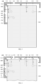
- FIG. 1 is a schematic diagram illustrating a first structure of an antenna apparatus according to an embodiment of the present disclosure
- FIG. 2 is a schematic diagram illustrating a current distribution excited by the antenna device shown in FIG. 1 .
- the antenna apparatus 100 includes a first radiator 110, a second radiator 120, a third radiator 130, a first feeding source 140 and a second feeding resource 150.
- the first radiator 110 and the second radiator 120 may be spaced apart from each other.
- a first coupling gap 101 may be provided between one end of the second radiator 120 and the first radiator 110, and a first ground terminal 121 may be provided at the other end of the second radiator 120.
- a free end of the first radiator 110 is close to the first coupling gap 101, and a free end of the second radiator 120 is also close to the first coupling gap 101, so that the free end of the first radiator 110 and the free end of the second radiator 120 are oppositely arranged at the first coupling gap 101.
- the first radiator 110 may be grounded at one end thereof away from the first coupling gap 101, and the second radiator 120 may also be grounded at one end thereof away from the first coupling gap 101, so that the first radiator 110 and the second radiator 120 may form an antenna with a parasitic branch.
- a first feeding terminal 111 may be provided on the first radiator 110.
- the first feeding terminal 111 may be located on a side of the first coupling gap 101 away from the first ground terminal 121.
- the first radiator 110 may be electrically connected to the first feeding source 140 through the first feeding terminal 111.
- the first feeding source 140 may be coupled to the first radiator 110. As shown in FIG. 2 , the first feeding source 140 may provide a first excitation signal I1 and feed it into the first radiator 110. The first excitation signal I1 is transmitted in the first radiator 110, and may be coupled into the second radiator 120 through the first coupling gap 101. The first excitation signal I1 may be grounded through the first ground terminal 121 of the second radiator 120. The first excitation signal I1 may excite at least a part of the first radiator 110 and the second radiator 120 to jointly generate a first resonance.
- the third radiator 130 may be located on a side of the second radiator 120 away from the first radiator 110, and the third radiator 130 may be connected to the second radiator 120.
- one end of the third radiator 130 may be connected to the first ground terminal 121, and the other end of the third radiator 130 may extend in a direction away from the second radiator 120.
- the third radiator 130 and the second radiator 120 may be one-piece formed, and the first ground terminal 121 may increase isolation between the third radiator 130 and the second radiator 120.
- a second ground terminal 131 may be provided at one end of the third radiator 130 away from the first ground terminal 121.
- the second ground terminal 131 may be spaced apart from the first ground terminal 121.
- an excitation current may be grounded through the second ground terminal 131, where the second ground terminal 131 may prevent the excitation current from flowing into the first ground terminal 121.
- a second feeding terminal 132 may also be provided on the third radiator 130, and the second feeding terminal 132 may be located on a side of the second ground terminal 131 away from the first ground terminal 121.
- the second feeding source 150 may be coupled to the third radiator 130 on a side of the second ground terminal 131 away from the first ground terminal 121.
- the second feeding source 150 may be electrically connected to the third radiator 130 through the second feeding terminal 132.
- the second feeding source 150 may provide a second excitation signal I2, and feed the second excitation signal I2 into a part of the third radiator 130 located on a side of the second ground terminal 131 away from the first ground terminal 121.
- the second excitation signal I2 is transmitted in the part of the third radiator 130, to excite the part of the third radiator 130 located on the side of the second ground terminal 131 away from the first ground terminal 121 to generate a second resonance.
- the second feeding source 150 provides the second excitation signal I2
- a part of the second excitation signal I2 may be grounded through the second ground terminal 131, without flowing into the first ground terminal 121 and the second radiator 120. This avoids the second excitation signal I2 from interfering with the first resonance, and isolation between the first resonance and the second resonance can be further increased.
- a length of the third radiator 130 may be longer than a length of the first radiator 110 or a length of the second radiator 120, so that the third radiator 130 may form a long-branched antenna radiator.
- the current for the first resonance is mainly distributed on the second radiator 120, and the current for the second resonance is mainly distributed at one side of the third radiator 130 away from the second radiator 120.
- the first coupling gap 101 is provided between the second radiator 120 and the first radiator 110, and the first ground terminal 121 is provided at one end of the second radiator 120 away from the first coupling gap 101.
- the third radiator 130 is connected to the first ground terminal 121.
- the second radiator 120 is located between the first radiator 110 and the third radiator 130.
- the second ground terminal 131 is provided on the third radiator 130, and the second ground terminal 131 is spaced apart from the first ground terminal 121.
- the first feeding source 140 is coupled to the first radiator 110.
- the first excitation signal I1 provided by the first feeding source 140 may be coupled to the second radiator 120 through the first coupling gap 101, to excite at least part of the first radiator 110 and the second radiator 120 to jointly generate the first resonance.
- the second feeding source 150 is coupled to the third radiator 130 on a side of the second ground terminal 131 away from the first ground terminal 121.
- the second feeding source 150 may provide the second excitation signal I2, to excite a part of the third radiator 130 located on a side of the second ground terminal 131 away from the first ground terminal 121 to generate the second resonance.
- the structure of the plurality of radiators is compact, and the space occupied by the radiators is small, which enables miniaturization of the antenna apparatus 100.
- the second excitation signal I2 may excite the part of the third radiator 130, located on a side of the second ground terminal 131 away from the first ground terminal 121, to generate the second resonance, and the second ground terminal 131 may prevent flowing of the second excitation signal I2 from the third radiator 130 into the first ground terminal 121 which would otherwise affect the first resonance.
- good isolation is enabled between the first resonance and the second resonance, and the first resonance and the second resonance each can have better radiation performance.
- the resonant frequency range of the first resonance may be the same as the resonant frequency range of the second resonance. And even if the antenna apparatus 100 transmits two radio signals at the same frequency band, the isolation may enable the communication requirement to be met.
- the first resonance and the second resonance may provide multiple-in multiple-out (multiple-in multiple-out, MIMO) transmission.
- the resonant frequency range of the first resonance may be different from the resonant frequency range of the second resonance.
- the mutual coupling between the first resonance and the second resonance at different resonance frequencies is weak, and the isolation between the first resonance and the second resonance is better.
- the second ground terminal 131 may be directly electrically connected to the ground plane 200 for grounding.
- the second ground terminal 131 may also be electrically connected to the ground plane 200 through other electronic elements or electronic components.
- the antenna apparatus 100 may further include a first matching circuit M1. One end of the first matching circuit M1 is coupled to the third radiator 130 through the second ground terminal 131, and the other end of the first matching circuit M1 is grounded.
- the first matching circuit M1 may short out a part of the second excitation signal I2, for generation of the second resonance as mentioned above.
- the first matching circuit M1 may short out the second excitation signal 12, it may mean that the impedance of the first matching circuit M1 is infinitely small at the frequency band of the second excitation signal I2, so that the second excitation signal I2 is grounded. As shown in FIG. 2 , when the second feeding source 150 feeds the second excitation signal I2 to the third radiator 130, a part of the second excitation signal I2 may be grounded through the first matching circuit M1.
- the first matching circuit M1 may at least include one circuit branch having an impedance of zero ohm.
- the first matching circuit M1 may make the current branch of zero ohm electrically connected to the third radiator 130, and a part of the second excitation signal I2 may be grounded through the circuit branch of zero ohm .
- the first matching circuit M1 may further include other circuit branches formed by any combination of an inductor, a capacitor and a resistor, which will not be described in detail herein.
- the first matching circuit sM1 may not turn on the circuit branch of zero ohm.
- the effective electrical length of the third radiator 130 may be an extended length from the first ground terminal 121 to the end of the third radiator 130 away from the first ground terminal 121.
- the first matching circuit M1 may perform impedance matching on the wireless signal transmitted by the third radiator 130 in this case.
- the first matching circuit M1 is coupled between the second ground terminal 131 and the ground plane 200.
- the first matching circuit M1 may short out the second excitation signal I2, to avoid the influence of the second excitation signal I2 on the first excitation signal I1, and increase the isolation between the first resonance and the second resonance.
- the first matching circuit M1 may not turn on the circuit branch of zero ohm, and the first matching circuit M1 may tune this radio signal to ensure radiation performance of the third radiator 130.
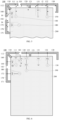
- FIG. 3 is a schematic diagram illustrating a second structure of an antenna apparatus according to an embodiment of the present disclosure
- FIG. 4 is a first schematic diagram illustrating a current distribution excited by the antenna apparatus shown in FIG. 3
- FIG. 5 is a second schematic diagram illustrating the current distribution excited by the antenna apparatus shown in FIG. 3
- the antenna apparatus 100 may further include a fourth radiator 160, a fifth radiator 170, a third feeding source 180, a second matching circuit M2, and a third matching circuit M3.
- the matching circuit may also be referred to as a matching network, a tuning circuit, a tuning network, etc.
- the fourth radiator 160 may be connected to the first radiator 110.
- the first radiator 110 may be provided with a third ground terminal 112 at one end of the first radiator 110 away from the second radiator 120.
- One end of the fourth radiator 160 may be connected to the third ground terminal 112, and the other end of the fourth radiator 160 may extend in a direction away from the third ground terminal 112, so that the third radiator 130 and the fourth radiator 160 are connected into a whole.
- the third ground terminal 112 may be located at one end of the first radiator 110 away from the first coupling gap 101, and the first feeding terminal 111 may be located between the third ground terminal 112 and the first coupling gap 101.
- the fourth radiator 160 may be located on a side of the first radiator 110 away from the second radiator 120, that is, the first radiator 110 may be located between the fourth radiator 160 and the second radiator 120.
- the fourth radiator 160 may share the third ground terminal 112 with the first radiator 110, and the third ground terminal 112 may increase the isolation between the fourth radiator 160 and the first radiator 110.
- One end of the second matching circuit M2 may be coupled to the fourth radiator 160, and the other end of the second matching circuit M2 may be grounded.
- the second matching circuit M2 may perform impedance matching on an excitation signal flowing through the fourth radiator 160.
- the fifth radiator 170 may be spaced apart from the fourth radiator 160.
- a second coupling gap 102 may be provided between one end of the fifth radiator 170 and the fourth radiator 160, and the other end of the fifth radiator 170 may extend in a direction away from the fourth radiator 160.
- the free end of the fourth radiator 160 is close to the second coupling gap 102, the free end of the fifth radiator 170 is also close to the second coupling gap 102, and the free end of the fourth radiator 160 and the free end of the fifth radiator 170 are oppositely arranged at the second coupling gap 102.
- a fourth ground terminal 171 may be provided at one end of the fifth radiator 170 away from the second coupling gap 102.
- the fifth radiator 170 may be grounded when the fourth ground terminal 171 is electrically connected with the ground plane 200 of the antenna apparatus 100 or the electronic device 10. In this way, the fourth radiator 160 and the fifth radiator 170 may also form an antenna with a parasitic branch.
- the fifth radiator 170 may be located on a side of the fourth radiator 160 away from the first radiator 110, that is, the fourth radiator 160 may be located between the fifth radiator 170 and the first radiator 110.
- the fifth radiator 170, the second coupling gap 102, the fourth radiator 160, the first radiator 110, the second coupling gap 102, and the third radiator 130 may be arranged in sequence.
- a third feeding terminal 172 may further be provided on the fifth radiator 170.
- the third feeding terminal 172 may be located between the fourth ground terminal 171 and the second coupling gap 102.
- the third feeding source 180 may be coupled to the fifth radiator 170, for example, the third feeding source 180 may be electrically connected to the fifth radiator 170 through the third feeding terminal 172 of the fifth radiator 170.
- the third matching circuit M3 may be coupled between the third feeding source 180 and the fifth radiator 170.
- the third matching circuit M3 may perform impedance matching on an excitation signal provided by the third feeding source 180.
- the second matching circuit M2 and the third matching circuit M3 each may include a circuit composed of any series connection or any parallel connection of a capacitor, an inductor, and a resistor, which will not be described in detail herein.
- the antenna apparatus 100 in the embodiment of the present disclosure may operate in a standalone (Standalone, SA) mode.
- the third feed source 180 may provide a third excitation signal 13
- the third excitation signal I3 may be fed, after being tuned by the third matching circuit M3, into the fifth radiator 170 from the third feeding terminal 172, and it may flow on the fifth radiator 170 and be grounded from the fourth ground terminal 171 located at the end away from the first coupling gap 101; as such, the fifth radiator 170 may generate a third resonance under the tuning of the third matching circuit M3.
- the third resonance is generated by the fifth radiator 170; in this case, the third resonance and the first resonance may be separated by a length of the fourth radiator 160 and a length of the first radiator 110, and the third resonance and the second resonance may be separated by the length of the fourth radiator 160, the length of the first radiator 110, and the length of a part of the third radiator 130, thus there is not only good isolation between the third resonance and the first resonance, but also good isolation between the third resonance and the second resonance.
- the resonant frequency range of the first resonance, the resonant frequency range of the second resonance, and the resonant frequency range of the third resonance may be the same. And even if the antenna apparatus 100 transmits three wireless signals of the same frequency band, such isolation may also enable the communication requirement to be met.
- the first resonance, the second resonance, and the third resonance may provide multiple-input multiple-output (MIMO) transmission.
- one or two of the resonant frequency range of the first resonance, the resonant frequency range of the second resonance, and the resonant frequency range of the third resonance may be different from the other two or the other one of the three resonant frequency ranges, or the resonant frequency range of the first resonance, the resonant frequency range of the second resonance and the resonant frequency range of the third resonance may be different from each other.
- the mutual coupling among the first resonance, the second resonance, and the third resonance at different resonance frequencies is weak, and the isolation among the first resonance, the second resonance, and the third resonance is better.
- the antenna apparatus 100 in the embodiment of the present disclosure may further operate in a non-standalone (Non-standalone, NSA) mode.
- the third feeding source 180 may further provide a fourth excitation signal I4.
- the fourth excitation signal I4 is fed, after being tuned by the third matching circuit M3, into the fifth radiator 170 through the third feeding terminal 172, and the fifth radiator 170 may generate a fourth resonance under the tuning of the third matching circuit M3.
- the fourth radiator 160 may generate a third resonance under tuning of the second matching circuit M2.
- the third resonance generated by the fourth radiator 160 may be grounded through the third ground terminal 112, the first resonance may be grounded through the first ground terminal 121, and the third ground terminal 112 and the first ground terminal 121 is separated by the length of the first radiator 110 and the length of the second radiator 120. As such, a point where the third resonance generated by the fourth radiator 160 is grounded is far from a point where the first resonance is grounded. There is good isolation between the third resonance generated by the fourth radiator 160 and each of the first resonance and the second resonance.
- the resonant frequency range of the first resonance, the resonant frequency range of the second resonance, and the resonant frequency range of the third resonance generated by the fourth radiator 160 may be the same. And even if the antenna apparatus 100 transmits three wireless signals of a same frequency band, such isolation may also enable the communication requirement to be met.
- the first resonance, the second resonance, and the third resonance generated by the fourth radiator 160 may provide MIMO transmission.
- one or two of the resonant frequency range of the first resonance, the resonant frequency range of the second resonance, and the resonant frequency range of the third resonance generated by the fourth radiator 160 may also be different from the other two or the other one of the three resonant frequency ranges, or the resonant frequency range of the first resonance, the resonant frequency range of the second resonance and the resonant frequency range of the third resonance generated by the fourth radiator 160 may be different from each other, so as to increase the isolation between the resonances.
- the resonant frequency of the third resonance may be different from the resonant frequency of the fourth resonance.
- the resonant frequency band of the fourth resonance may be the B3 frequency band (1.71 GHz to 1.88 GHz)
- the resonant frequency band of the third resonance may be the N41 frequency band (2.5 GHz to 2.69 GHz).
- the fifth radiator 170 may generate the fourth resonance under the tuning of the third matching circuit M3, and the fourth radiator 160 may generate the third resonance under the tuning of the second matching circuit M2. That is, when the third feeding source 180 feeds one excitation signal, two resonances may be generated by the fifth radiator 170 and the fourth radiator 160 respectively, which enables miniaturization of the antenna apparatus 100. Moreover, there is good isolation between the third resonance/fourth resonance and each of the first resonance and the second resonance, and the radiation performance of the antenna apparatus 100 can be thus improved.
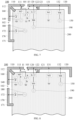
- FIG. 6 is a schematic diagram illustrating a third structure of an antenna apparatus according to an embodiment of the present disclosure
- FIG. 7 is a first schematic diagram illustrating a current distribution excited by the antenna apparatus shown in FIG. 6
- the antenna apparatus 100 may further include a fourth feeding source 190.
- the fourth feeding source 190 may be coupled to the second radiator 120, to excite the second radiator 120 and the first radiator 110 to generate a fifth resonance.
- a fourth feeding terminal 122 may be provided on the second radiator 120.
- the fourth feeding terminal 122 may be located between the first coupling gap 101 and the first ground terminal 121.
- the fourth feeding source 190 may be electrically connected to the second radiator 120 through the fourth feeding terminal 122.
- the fourth feeding source 190 may provide a fifth excitation signal 15.
- the fifth excitation signal I5 is transmitted on the second radiator 120, and may be coupled to the first radiator 110 through the first coupling gap 101, to excite at least part of the second radiator 120 and at least part of the first radiator 110 to jointly generate the fifth resonance.
- the first resonance is generated jointly by the first radiator 110 and the second radiator 120
- the fifth resonance is also generated jointly by the first radiator 110 and the second radiator 120.
- the first radiator 110 and the second radiator 120 may be reused, which enables miniaturization of the antenna apparatus 100.
- the resonant frequency range of the fifth resonance may be different from the resonant frequency range of the first resonance, and the first radiator 110 and the second radiator 120 may generate at least one of the first resonance and the fifth resonance.
- the fifth resonance may also be generated simultaneously with one or more of the second resonance, the third resonance, and the fourth resonance. In these resonances, a point where the fifth resonance is grounded is relatively close to a point where the fourth resonance is grounded.
- the third ground terminal 112 may make the isolation between the fifth resonance and the fourth resonance increased, and also ensure the radiation performance of the fifth resonance and the radiation performance of the fourth resonance.
- the resonant frequency range of the fifth resonance may be the same as the resonant frequency range of the fourth resonance, the resonant frequency range of the second resonance, and the resonant frequency range of the third resonance. And even if the antenna apparatus 100 transmits multiple wireless signals of a same frequency band, such isolation may also enable the communication requirement to be met.
- the multiple resonances may provide MIMO transmission.
- the resonant frequency range of the fifth resonance may also be different from the resonant frequency range(s) of one or more of other resonances, to increase the isolation among the multiple resonances.
- the antenna apparatus 100 in the embodiments of the present disclosure may further include a first filter circuit LC1.
- the filter circuit may also be referred to as a filter network.
- the first filter circuit LC1 may include a first end a and a second end b.
- the first end a may be coupled between the first feeding source 140 and the first radiator 110, for example, it may be coupled between the first feeding source 140 and the first feeding terminal 111.
- the second end b may be grounded.
- the first filter circuit LC1 may short out the fifth excitation signal 15, for the generation of the fifth resonance.
- the first filter circuit LC1 shorts out the fifth excitation signal I5
- the resistance of the first filter circuit LC1 is infinitely small at the frequency band of the fifth excitation signal I5, so that the fifth excitation signal I5 is grounded.
- the fifth excitation signal I5 may, after being coupled to the first radiator 110 through the first coupling gap 101, be grounded through the first filter circuit LC1.
- the first filter circuit LC1 may include a circuit composed of any series connection or any parallel connection of a capacitor, an inductor, and a resistor. Details thereof are not described herein.
- the antenna module of the embodiment of the present disclosure is provided with the first filter circuit LC1.
- the first filter circuit LC1 can prevent the fifth excitation signal I5 from being grounded through the third ground terminal 112, so as to avoid coincidence with the point where the current of the fourth excitation signal I4 is grounded.
- good isolation can also be provided between the fourth resonance and fifth resonance adjacent to each other, and the fourth resonance and the fifth resonance can provide good radiation performance.
- the first end a of the first filter circuit LC1 is coupled between the first feeding source 140 and the first radiator 110, and the first filter circuit LC1 can also prevent flowing of the fifth excitation signal I5 into the first feeding source 140 which would otherwise affect the performance of the first feeding source 140, so as to ensure the normal formation of the first resonance.
- FIG. 8 is a second schematic diagram illustrating the current distribution excited by the antenna apparatus shown in FIG.6 .
- the antenna apparatus 100 may further include a second filter circuit LC2.
- the second filter circuit may be a filter circuit.
- One end of the second filter circuit LC2 may be electrically connected to the fourth feeding terminal 122 of the second radiator 120, and the other end of the second filter circuit LC2 may be electrically connected to the fourth feeding source 190.
- the second filter circuit LC2 is coupled between the fourth feeding source 190 and the second radiator 120.
- the second filter circuit LC2 may be an open circuit to the first excitation signal I1 fed by the first feeding source 140, for the generation of the first resonance mentioned above.
- the second filter circuit LC2 is an open circuit to the first excitation signal I1
- the second filter circuit LC2 may include a circuit composed of any series connection or any parallel connection of a capacitor, an inductor, and a resistor. Details thereof are not described herein.
- the antenna module of the embodiment of the present disclosure is provided with the second filter circuit LC2.
- the second filter circuit LC2 is an open circuit to the first excitation signal I1.
- the second filter circuit LC2 can prevent flowing of the first excitation signal I1 into the fourth feeding source 190 which would otherwise affect the performance of the fourth feeding source 190, so as to ensure the normal operation of the fifth resonance.
- the first excitation signal I1 may, after being coupled to the second radiator 120 through the second coupling gap 102, be grounded through the farthest first ground terminal 121, thereby ensuring the isolation between the first resonance and the fourth resonance.
- the antenna apparatus 100 may further include a fourth matching circuit M4, a fifth matching circuit M5, and a sixth matching circuit M6.
- the fourth matching circuit M4 may be coupled between the fourth feeding source 190 and the second radiator 120.
- the fourth matching circuit M4 is connected in series between the fourth feeding source 190 and the fourth feeding terminal 122.
- the fourth matching circuit M4 may perform impedance matching on the fifth excitation signal 15 provided by the fourth feeding source 190, so that the second radiator 120 and the first radiator 110 may generate the fifth resonance.
- the fifth matching circuit M5 may be coupled between the first feeding source 140 and the first radiator 110.
- the fifth matching circuit M5 is connected in series between the first feeding source 140 and the first feeding terminal 111.
- the fifth matching circuit M5 may perform impedance matching on the first excitation signal I1 provided by the first feeding source 140, so that the first radiator 110 and the second radiator 120 may generate the first resonance.
- the sixth matching circuit M6 may be coupled between the second feeding source 150 and the third radiator 130.
- the sixth matching circuit M6 is connected in series between the second feeding source 150 and the second feeding terminal 132.
- the sixth matching circuit M6 may perform impedance matching on the second excitation signal I2 provided by the second feeding source 150, so that the third radiator 130 may generate the second resonance.
- the fourth matching circuit M4, the fifth matching circuit M5, and the sixth matching circuit M6 each may include a circuit composed of any series connection or any parallel connection of a capacitor, an inductor, and a resistor, which will not be described in detail herein.
- the first matching circuit M1, the second matching circuit M2, the third matching circuit M3, the fourth matching circuit M4, the fifth matching circuit M5, and the sixth matching circuit M6 may have a different structure.
- the structures of the matching circuits mentioned above are not limited in the embodiments of the present disclosure.
- the antenna apparatus 100 in the embodiments of the present disclosure may better generate the first resonance, the second resonance, the third resonance, the fourth resonance, and the fifth resonance under the action of the matching circuits mentioned above.
- the antenna apparatus 100 of the embodiment of the present disclosure may generate the first resonance to the fifth resonance, so that the antenna apparatus 100 can be applied in 5G communication.
- it may be applied in a 5G NSA mode, or a 5G SA mode.
- the antenna apparatus 100 In the SA mode, the antenna apparatus 100 only needs to operate in a New Radio Access Technology in 3GPP (New Radio Access Technology in 3GPP, NR for short) state.
- 3GPP New Radio Access Technology in 3GPP, NR for short
- the antenna apparatus 100 In the NSA mode, the antenna apparatus 100 needs to operate in a Long Term Evolution (Long Term Evolution, LTE) state and the NR state simultaneously; and in this case, the fourth radiator 160 and the fifth radiator 170 may simultaneously generate the third resonance and the fourth resonance, so that the antenna apparatus 100 may operate at a B3 frequency band (1.71 GHz to 1.88 GHz) and a N41 frequency band (2.5 GHz to 2.69 GHz) simultaneously.
- the decoupling principle of the antenna apparatus 100 is set forth below by utilizing the antenna apparatus 100 operating in the SA mode and the NSA mode, respectively.
- the antenna apparatus 100 When the antenna apparatus 100 is in the SA mode, the antenna apparatus 100 only needs to operate in the NR state.
- the first feeding source 140 may feed the first excitation signal I1 to the first feeding terminal 111.
- the first radiator 110 and the second radiator 120 are coupled through the first coupling gap 101 under the action of the first excitation signal I1, to generate a first resonance.
- the first resonance may be in the N41 frequency band.
- the second feeding source 150 feeds the second excitation signal I2 to the second feeding terminal 132
- the third radiator 130 may generate a second resonance under the action of the second excitation signal I2.
- the second resonance may also be in the N41 frequency band.
- the third matching circuit M3 may perform impedance matching on the third excitation signal I3, so that the third excitation signal I3 may be grounded through the fourth ground terminal 171 (for example, the resonant frequency band of the third matching circuit M3 is tuned to the N41 frequency band, the resonant frequency band of the second matching circuit M2 is always fixed in the N41 frequency band; and when the third excitation signal I3 is in the N41 frequency band, the third excitation signal I3 may be grounded through the nearest fourth ground terminal 171) to generate the third resonance.
- the third resonance may also be in the N41 frequency band. In this way, the antenna apparatus 100 may provide three resonances of N41 frequency band (the first resonance, the second resonance, and the third resonance).
- the first radiator 110 and the second radiator 120 may generate the first resonance; the third radiator 130 may generate the second resonance; and the fifth radiator 170 may generate the third resonance.
- the first resonance, the second resonance, and the third resonance may be in the same N41 frequency band.
- the first resonance and the second resonance are separated by at least the length of the third radiator 130, and the first resonance and the fifth resonance are separated by at least the length of the fourth radiator 160; thus, isolation in a great level is provided among the multiple resonances.
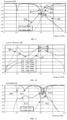
- FIG. 9 is a schematic diagram illustrating reflection coefficient curves of the antenna apparatus according to the embodiments of the disclosure at the N41 frequency band in the SA mode
- FIG. 10 is a schematic diagram illustrating system efficiency curves of the antenna apparatus according to the embodiments of the present disclosure at the N41 frequency band in the SA mode. As shown in FIG. 9 and FIG. 10, FIG. 9 is a schematic diagram illustrating reflection coefficient curves of the antenna apparatus according to the embodiments of the disclosure at the N41 frequency band in the SA mode, and FIG. 10 is a schematic diagram illustrating system efficiency curves of the antenna apparatus according to the embodiments of the present disclosure at the N41 frequency band in the SA mode. As shown in FIG.
- curve S1 represents the reflection coefficient curve of the first resonance at the N41 frequency band
- curve S2 represents the reflection coefficient curve of the second resonance at the N41 frequency band
- curve S3 represents the reflection coefficient curve of the third resonance at the N41 frequency band
- curve S4 represents a curve of isolation between the first resonance and the second resonance at the N41 frequency band
- curve S5 represents a curve of isolation between the first resonance and the third resonance at the N41 frequency band.
- the first resonance may be grounded through the first ground terminal 121; the second resonance may be formed at a place away from the first ground terminal 121, and the second ground terminal 131 may prevent flowing of the second excitation signal I2 into the second radiator 120 which would otherwise affect the first resonance; the third resonance is grounded through the fourth ground terminal 171. Therefore, there is a long distance between the first resonance and the second resonance, and there is also a long distance between the first resonance and the third resonance. As shown in FIG. 9 , the isolation between the first resonance and the second resonance is better than -16.9 dB, and the isolation between the first resonance and the third resonance is better than -14.9 dB. Thus, there is good isolation among the three resonances in the embodiments of the present disclosure.
- curve S6 represents the system efficiency curve of the first resonance at the N41 frequency band
- curve S7 represents the system efficiency curve of the second resonance at the N41 frequency band
- curve S8 represents the system efficiency curve of the third resonance at the N41 frequency band.
- the system efficiency of the first resonance at the N41 frequency band is about -5.1 dB to -3.3 dB
- the system efficiency of the second resonance at the N41 frequency band is about -7.4 dB to -5 dB
- the system efficiency of the third resonance at the N41 frequency band is about -3.1 dB to -2.5 dB.
- the adjacent radiators when the adjacent radiators operate at the same frequency band, good isolation can be provided between different resonances generated by using different radiators, thereby ensuring that the first resonance, the second resonance, and the third resonance can operate normally and simultaneously in the SA mode.
- the first matching circuit M1 serves as an equivalent short circuit at the N41 frequency band, for the current to is grounded; this can also avoid the influence of the second resonance on the first resonance, so as to further increase the isolation between the antennas.
- the antenna apparatus 100 When the antenna apparatus 100 is in the NSA mode, the antenna apparatus 100 needs to operate in the LTE state and NR state simultaneously. It is illustrated by taking, as an example, a case where the antenna apparatus 100 is in a combination state of the B3 frequency band and the N41 frequency band.
- the first feeding source 140 may feed the first excitation signal I1 to the first feeding terminal 111, and the first radiator 110 and the second radiator 120 are coupled through the first coupling gap 101 under the action of the first excitation signal I1, to generate a first resonance.
- the first resonance may be in the N41 frequency band.
- the second feeding source 150 feeds the second excitation signal I2 to the second feeding terminal 132
- the third radiator 130 may generate a second resonance under the action of the second excitation signal I2.
- the second resonance may also be in the N41 frequency band.
- the third matching circuit M3 may perform impedance matching on the fourth excitation signal I4, so that the fifth radiator 170 may generate a fourth resonance.
- the fourth resonance may be in the B3 frequency band.
- the fourth excitation signal I4 may be coupled to the fourth radiator 160 through the second coupling gap 102, and grounded from the second matching circuit M2 of the fourth radiator 160.
- the second matching circuit M2 may perform impedance matching on the fourth excitation signal I4, to excite the fourth radiator 160 to generate a third resonance.
- the third resonance may be in the N41 frequency band. In this way, the antenna apparatus 100 may provide a resonance of B3 frequency band (the fourth resonance) and three resonances of N41 frequency band (the first resonance, the second resonance, and the third resonance).
- the first radiator 110 and the second radiator 120 may generate the first resonance; the third radiator 130 may generate the second resonance; the fifth radiator 170 may generate the fourth resonance; and the fourth radiator 160 may generate the third resonance.
- the first resonance, the second resonance, and the third resonance may be in the same N41 frequency band, and the fourth resonance may be in the B3 frequency band. Since the isolation between the first resonance and the second resonance may be increased through the first ground terminal 121, a point where the current of the first resonance is grounded is different from a point where the current of the third resonance is grounded; thus, isolation in a great level is provided between the multiple resonances.
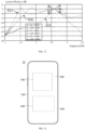
- FIG. 11 is a schematic diagram illustrating reflection coefficient curves of the antenna apparatus according to the embodiments of the present disclosure at the N41 frequency band in the NSA mode
- FIG. 12 is a schematic diagram illustrating system efficiency curves of the antenna apparatus according to the embodiments of the present disclosure at the N41 frequency band in the NSA mode. As shown in FIG. 11 and FIG. 12 , FIG. 11 is a schematic diagram illustrating reflection coefficient curves of the antenna apparatus according to the embodiments of the present disclosure at the N41 frequency band in the NSA mode, and FIG. 12 is a schematic diagram illustrating system efficiency curves of the antenna apparatus according to the embodiments of the present disclosure at the N41 frequency band in the NSA mode. As shown in FIG.
- curve S9 represents the reflection coefficient curve of the first resonance at the N41 frequency band
- curve S10 represents the reflection coefficient curve of the second resonance at the N41 frequency band
- curve S11 represents the reflection coefficient curve of the third resonance at the N41 frequency band
- curve S12 represents a curve of isolation between the first resonance and the second resonance at the N41 frequency band
- curve S13 represents a curve of isolation between the first resonance and the third resonance at the N41 frequency band. Since the isolation between the first resonance and the second resonance is increased through the first ground terminal 121, the first resonance is grounded through the first ground terminal 121, and the third resonance is grounded through the third ground terminal 112, there is a long distance between the first resonance and the third resonance. It can be seen from FIG.
- curve S14 represents the system efficiency curve of the first resonance at the N41 frequency band
- curve S15 represents the system efficiency curve of the second resonance at the N41 frequency band
- curve S16 represents the system efficiency curve of the third resonance at the N41 frequency band.
- the system efficiency of the first resonance at the N41 frequency band is about -5.4 dB to -3.8 dB
- the system efficiency of the second resonance at the N41 frequency band is about -7.4 dB to -5 dB
- the system efficiency of the third resonance at the N41 frequency band is about -5.7 dB to -3.3 dB.
- the antenna apparatus 100 of the embodiments of the present disclosure when adjacent radiators operate at the same frequency band, good isolation can be provided between different resonances generated by different radiators, and it is possible to ensure that the first resonance, the second resonance, and the third resonance can operate normally and simultaneously in the NSA mode.
- the first resonance to the fifth resonance of the present disclosure may operate at many frequency bands at the same time.
- frequency bands may include, but are not limited to, a low-frequency band (B28/B20/B5/B8), a medium-high frequency band (B3/B1/B40B41), a 2.4G/5G Wi-Fi band, and a 5G band (N41/N78/N79), and this is not limited in the embodiment of the present disclosure.
- an electronic device is also provided according to an embodiment of the present disclosure.
- the electronic device may be a smartphone, a tablet computer, etc., or it may also be a game device, an Augmented Reality (Augmented Reality, AR) device, an in-vehicle device, a data storage device, an audio playback device, a video playback device, a notebook computer, or a desktop computing device, etc.
- FIG. 13 is a structural schematic diagram of an electronic device according to an embodiment of the present disclosure.
- the electronic device 10 may further include a display screen 300, a middle frame 400, a circuit board 500, a battery 600, and a rear case 700.
- the display screen 300 is provided on the middle frame 400, to provide a display surface of the electronic device 10 for displaying information such as an image and text.
- the display screen 300 may include a liquid crystal display (Liquid Crystal Display, LCD) or an organic light-emitting diode (Organic Light-Emitting Diode, OLED) display 300 or the like.
- the display screen 300 may be a full screen. In this case, the entire area of the display screen 300 serves as the display area, and no non-display area is included, or the non-display area occupies only a small part of the display screen 300 for the user, so that the display screen 300 has a large screen ratio.
- the display screen 300 may not be a full screen, and the display screen 300 includes a display area and a non-display area adjacent to the display area. The display area is configured to display information, and the non-display area does not display information.
- a cover plate may also be provided on the display screen 300 to protect the display screen 300, and prevent the display screen 300 from being scratched or damaged by water.
- the cover plate may be a transparent glass cover plate, so that the user can observe the contents displayed on the display screen 300 through the cover plate.
- the cover plate may be a glass cover plate made of sapphire.
- the middle frame 400 may be in a thin-plate-like structure or a thin-flake-like structure, or may be in a hollow frame structure.
- the middle frame provides support for the electronic components or functional components in the electronic device 10, so as to mount the electronic components and functional components of the electronic device 10 together.
- a structure such as a groove, a protrusion, and a through hole, may be defined on the middle frame 400, to facilitate the installation of the electronic components or the functional components of the electronic device 10.
- the middle frame may be made from a metal, plastic or the like.
- the middle frame 400 when the middle frame 400 is made of a metal, the first radiator 110, the second radiator 120, the third radiator 130, the fourth radiator 160, and the fifth radiator 170 may be multiple metal branches on the middle frame 400.
- the first coupling gap 101 and the second coupling gap 102 may be provided on the middle frame 400, to form the first radiator to the fifth radiator.
- the middle frame 400 may be reused as a radiator, thereby saving the space occupied by the radiator.
- the circuit board 500 is fixedly provided on the middle frame 400, and the circuit board 500 is sealed inside the electronic device 10 through the rear case 700.
- the circuit board 500 may be a main board of the electronic device 10.
- a processor may be integrated on the circuit board 500; in addition, one or more of functional components such as an earphone interface, an acceleration sensor, a gyroscope, and a motor may also be integrated on the circuit board 500.
- the display screen 300 may be electrically connected to the circuit board 500, so that the display of the display screen 300 may be controlled by the processor on the circuit board 500.
- one or more of the first feeding source 140, the second feeding source 150, the third feeding source 180, the fourth feeding source 190, the first filter circuit LC1, the second filter circuit LC2, the first matching circuit M1, the second matching circuit M2, the third matching circuit M3, the fourth matching circuit M4, the fifth matching circuit M5, and the sixth matching circuit M6 of the antenna apparatus 100 may be provided on the circuit board 500.
- the above components may also be provided on a small board of the electronic device 10, which is not limited herein.
- one or more of the first radiator 110, the second radiator 120, the third radiator 130, the fourth radiator 160, and the fifth radiator 170 may also be provided on the circuit board 500, for example, one or more of them is formed on one surface of the circuit board 500 by etching, spraying or the like.
- the radiators may also be provided on a bracket of the electronic device 10 in such a manner that the radiators are located inside the electronic device 10.
- the battery 600 is provided on the middle frame 400, and the battery 600 is sealed inside the electronic device 10 by the rear case 700.
- the battery 600 is electrically connected to the circuit board 500, for supplying power to the electronic device 10.
- a power management circuit may be provided on the circuit board 500.
- the power management circuit is configured to distribute the voltage provided by the battery 600 to various electronic components in the electronic device 10.
- the rear case 700 is connected to the middle frame 400.
- the rear case 700 may be attached to the middle frame 400 by an adhesive such as a double-sided tape, so as to be connected with the middle frame 400.
- the rear case 700 is used to seal, together with the middle frame 400 and the display screen 300, the electronic components and the functional components of the electronic device 10 inside the electronic device 10, so as to protect the electronic components and the functional components of the electronic device 10.
Landscapes
- Engineering & Computer Science (AREA)
- Computer Networks & Wireless Communication (AREA)
- Details Of Aerials (AREA)
- Support Of Aerials (AREA)
Applications Claiming Priority (2)
| Application Number | Priority Date | Filing Date | Title |
|---|---|---|---|
| CN202011580857.7A CN112736432B (zh) | 2020-12-28 | 2020-12-28 | 天线装置及电子设备 |
| PCT/CN2021/127066 WO2022142659A1 (zh) | 2020-12-28 | 2021-10-28 | 天线装置及电子设备 |
Publications (2)
| Publication Number | Publication Date |
|---|---|
| EP4262015A1 true EP4262015A1 (de) | 2023-10-18 |
| EP4262015A4 EP4262015A4 (de) | 2024-07-03 |
Family
ID=75606342
Family Applications (1)
| Application Number | Title | Priority Date | Filing Date |
|---|---|---|---|
| EP21913404.6A Pending EP4262015A4 (de) | 2020-12-28 | 2021-10-28 | Antennenvorrichtung und elektronische vorrichtung |
Country Status (4)
| Country | Link |
|---|---|
| US (1) | US12334644B2 (de) |
| EP (1) | EP4262015A4 (de) |
| CN (1) | CN112736432B (de) |
| WO (1) | WO2022142659A1 (de) |
Families Citing this family (27)
| Publication number | Priority date | Publication date | Assignee | Title |
|---|---|---|---|---|
| CN110247160B (zh) * | 2019-04-30 | 2021-10-29 | 荣耀终端有限公司 | 一种天线组件及移动终端 |
| WO2021179808A1 (zh) * | 2020-03-12 | 2021-09-16 | Oppo广东移动通信有限公司 | 天线组件和电子设备 |
| CN114122710A (zh) * | 2020-08-28 | 2022-03-01 | 深圳富泰宏精密工业有限公司 | 天线结构及具有该天线结构的电子设备 |
| CN112736432B (zh) * | 2020-12-28 | 2022-07-15 | Oppo广东移动通信有限公司 | 天线装置及电子设备 |
| CN113193360A (zh) * | 2021-05-10 | 2021-07-30 | 西安电子科技大学 | 基于电磁耦合抵消的自解耦mimo天线 |
| CN115332792B (zh) * | 2021-05-11 | 2025-05-13 | Oppo广东移动通信有限公司 | 天线结构及电子设备 |
| CN115411492B (zh) * | 2021-05-26 | 2025-09-09 | Oppo广东移动通信有限公司 | 天线组件和电子设备 |
| CN113381188A (zh) * | 2021-06-23 | 2021-09-10 | 东莞市小精灵教育软件有限公司 | 一种天线结构及通信终端 |
| CN113437520B (zh) * | 2021-06-29 | 2022-08-16 | RealMe重庆移动通信有限公司 | 天线装置及电子设备 |
| CN115621730A (zh) * | 2021-07-16 | 2023-01-17 | 华为技术有限公司 | 天线结构及电子设备 |
| CN113572544B (zh) * | 2021-08-02 | 2023-07-18 | Tcl通讯(宁波)有限公司 | 天线通信装置、天线装置连接检测方法、终端及存储介质 |
| CN113644438B (zh) * | 2021-08-31 | 2024-11-19 | 维沃移动通信有限公司 | 天线装置及电子设备 |
| CN113871872B (zh) * | 2021-09-07 | 2022-08-16 | 荣耀终端有限公司 | 一种多天线系统及无线通信设备 |
| US11777212B2 (en) * | 2021-09-13 | 2023-10-03 | Htc Corporation | Antenna structure |
| CN114243259B (zh) * | 2021-11-12 | 2023-03-24 | 荣耀终端有限公司 | 一种终端天线系统及电子设备 |
| CN114221127B (zh) * | 2021-11-30 | 2022-11-01 | 荣耀终端有限公司 | 自解耦宽带天线系统和终端设备 |
| CN116247415A (zh) * | 2021-12-08 | 2023-06-09 | Oppo广东移动通信有限公司 | 电子设备及天线装置 |
| CN116345153A (zh) * | 2021-12-23 | 2023-06-27 | 华为技术有限公司 | 一种电子设备 |
| CN114284727A (zh) * | 2021-12-28 | 2022-04-05 | 上海创功通讯技术有限公司 | 一种mimo天线及电子设备 |
| CN117673734A (zh) * | 2022-08-22 | 2024-03-08 | Oppo广东移动通信有限公司 | 天线装置及电子设备 |
| CN115313030A (zh) * | 2022-08-31 | 2022-11-08 | Oppo广东移动通信有限公司 | 天线组件和电子设备 |
| CN118040289A (zh) * | 2022-11-04 | 2024-05-14 | 荣耀终端有限公司 | 一种终端天线和电子设备 |
| CN118572366A (zh) * | 2023-02-28 | 2024-08-30 | 华为技术有限公司 | 一种天线结构和电子设备 |
| CN116454628B (zh) * | 2023-04-28 | 2026-03-20 | 维沃移动通信有限公司 | 电子设备 |
| CN119581837B (zh) * | 2023-09-07 | 2025-11-11 | Oppo广东移动通信有限公司 | 电子设备 |
| TWM651614U (zh) * | 2023-10-13 | 2024-02-11 | 廣達電腦股份有限公司 | 穿戴式裝置 |
| CN121769500A (zh) * | 2024-09-30 | 2026-03-31 | 华为技术有限公司 | 天线系统和终端设备 |
Family Cites Families (15)
| Publication number | Priority date | Publication date | Assignee | Title |
|---|---|---|---|---|
| US9123990B2 (en) * | 2011-10-07 | 2015-09-01 | Pulse Finland Oy | Multi-feed antenna apparatus and methods |
| KR102306080B1 (ko) * | 2015-08-13 | 2021-09-30 | 삼성전자주식회사 | 안테나 장치 및 안테나 장치를 포함하는 전자 장치 |
| US11011837B2 (en) | 2016-11-17 | 2021-05-18 | Huawei Technologies Co., Ltd. | Communications terminal |
| CN107317095A (zh) * | 2017-06-30 | 2017-11-03 | 维沃移动通信有限公司 | 一种天线系统及移动终端 |
| TWI678028B (zh) * | 2017-12-12 | 2019-11-21 | 群邁通訊股份有限公司 | 天線結構及具有該天線結構之無線通訊裝置 |
| CN108321495B (zh) * | 2018-01-22 | 2020-05-19 | Oppo广东移动通信有限公司 | 天线组件、天线装置及电子设备 |
| CN108346863B (zh) * | 2018-01-29 | 2021-02-09 | 维沃移动通信有限公司 | 一种天线和移动终端 |
| CN108631041B (zh) * | 2018-04-25 | 2020-04-03 | Oppo广东移动通信有限公司 | 天线组件及电子装置 |
| CN108736130B (zh) * | 2018-07-11 | 2020-01-14 | Oppo广东移动通信有限公司 | 天线组件以及电子设备 |
| CN208522084U (zh) | 2018-07-24 | 2019-02-19 | Oppo广东移动通信有限公司 | 天线组件以及电子设备 |
| CN114824836B (zh) * | 2019-02-27 | 2025-04-08 | 华为技术有限公司 | 共体天线及电子设备 |
| CN110247160B (zh) * | 2019-04-30 | 2021-10-29 | 荣耀终端有限公司 | 一种天线组件及移动终端 |
| CN111244616B (zh) * | 2020-03-27 | 2022-01-11 | 维沃移动通信有限公司 | 一种天线结构及电子设备 |
| CN112086753B (zh) * | 2020-09-30 | 2025-03-04 | Oppo广东移动通信有限公司 | 天线组件和电子设备 |
| CN112736432B (zh) * | 2020-12-28 | 2022-07-15 | Oppo广东移动通信有限公司 | 天线装置及电子设备 |
-
2020
- 2020-12-28 CN CN202011580857.7A patent/CN112736432B/zh active Active
-
2021
- 2021-10-28 EP EP21913404.6A patent/EP4262015A4/de active Pending
- 2021-10-28 WO PCT/CN2021/127066 patent/WO2022142659A1/zh not_active Ceased
-
2023
- 2023-06-26 US US18/341,101 patent/US12334644B2/en active Active
Also Published As
| Publication number | Publication date |
|---|---|
| WO2022142659A1 (zh) | 2022-07-07 |
| US20230335922A1 (en) | 2023-10-19 |
| CN112736432B (zh) | 2022-07-15 |
| EP4262015A4 (de) | 2024-07-03 |
| CN112736432A (zh) | 2021-04-30 |
| US12334644B2 (en) | 2025-06-17 |
Similar Documents
| Publication | Publication Date | Title |
|---|---|---|
| US12334644B2 (en) | Antenna apparatus and electronic device | |
| CN112736461B (zh) | 天线装置及电子设备 | |
| CN112532275B (zh) | 射频模组、天线控制方法以及电子设备 | |
| CN113437520B (zh) | 天线装置及电子设备 | |
| US9793616B2 (en) | Shared antenna structures for near-field communications and non-near-field communications circuitry | |
| CN114530691A (zh) | 电子设备 | |
| CN110635821A (zh) | 射频电路及电子设备 | |
| US20150270618A1 (en) | Electronic Device With Indirectly Fed Slot Antennas | |
| EP4072029A1 (de) | Funkfrequenzmodul und elektronische vorrichtung | |
| WO2017114024A1 (zh) | 双极化天线和通信设备 | |
| CN111668604B (zh) | 天线组件及电子设备 | |
| US12519234B2 (en) | Ultra-wideband antenna assembly | |
| CN114512797A (zh) | 天线装置及电子设备 | |
| CN115000684A (zh) | 天线装置及电子设备 | |
| WO2023103664A1 (zh) | 电子设备及天线装置 | |
| CN108879112B (zh) | 天线阵列及终端 | |
| WO2023000733A1 (zh) | 天线装置的接地结构、天线装置及电子设备 | |
| WO2024087859A1 (zh) | 一种天线组件和电子设备 | |
| EP4224630B1 (de) | Antennenvorrichtung und elektronische vorrichtung | |
| CN112103624A (zh) | 天线装置及电子设备 | |
| CN118299794A (zh) | 电子设备 | |
| EP4668481A1 (de) | Elektronische vorrichtung | |
| US11990687B2 (en) | Ultra-wideband antenna having fed and unfed arms | |
| US20260074440A1 (en) | Electronic Device Antenna with Switchable Resonant Circuit | |
| US20260074412A1 (en) | Electronic Device Antenna with Housing-Integrated Parasitic |
Legal Events
| Date | Code | Title | Description |
|---|---|---|---|
| STAA | Information on the status of an ep patent application or granted ep patent |
Free format text: STATUS: THE INTERNATIONAL PUBLICATION HAS BEEN MADE |
|
| PUAI | Public reference made under article 153(3) epc to a published international application that has entered the european phase |
Free format text: ORIGINAL CODE: 0009012 |
|
| STAA | Information on the status of an ep patent application or granted ep patent |
Free format text: STATUS: REQUEST FOR EXAMINATION WAS MADE |
|
| 17P | Request for examination filed |
Effective date: 20230714 |
|
| AK | Designated contracting states |
Kind code of ref document: A1 Designated state(s): AL AT BE BG CH CY CZ DE DK EE ES FI FR GB GR HR HU IE IS IT LI LT LU LV MC MK MT NL NO PL PT RO RS SE SI SK SM TR |
|
| DAV | Request for validation of the european patent (deleted) | ||
| DAX | Request for extension of the european patent (deleted) | ||
| REG | Reference to a national code |
Ref country code: DE Ref legal event code: R079 Free format text: PREVIOUS MAIN CLASS: H01Q0001360000 Ipc: H01Q0001240000 |
|
| A4 | Supplementary search report drawn up and despatched |
Effective date: 20240531 |
|
| RIC1 | Information provided on ipc code assigned before grant |
Ipc: H01Q 9/42 20060101ALI20240524BHEP Ipc: H01Q 5/328 20150101ALI20240524BHEP Ipc: H01Q 5/307 20150101ALI20240524BHEP Ipc: H01Q 1/24 20060101AFI20240524BHEP |