EP4262032A1 - Structure de connexion et dispositif adaptateur - Google Patents
Structure de connexion et dispositif adaptateur Download PDFInfo
- Publication number
- EP4262032A1 EP4262032A1 EP22716844.0A EP22716844A EP4262032A1 EP 4262032 A1 EP4262032 A1 EP 4262032A1 EP 22716844 A EP22716844 A EP 22716844A EP 4262032 A1 EP4262032 A1 EP 4262032A1
- Authority
- EP
- European Patent Office
- Prior art keywords
- plugging
- structural member
- slot
- connection structure
- plug
- Prior art date
- Legal status (The legal status is an assumption and is not a legal conclusion. Google has not performed a legal analysis and makes no representation as to the accuracy of the status listed.)
- Withdrawn
Links
Images



Classifications
-
- H—ELECTRICITY
- H01—ELECTRIC ELEMENTS
- H01R—ELECTRICALLY-CONDUCTIVE CONNECTIONS; STRUCTURAL ASSOCIATIONS OF A PLURALITY OF MUTUALLY-INSULATED ELECTRICAL CONNECTING ELEMENTS; COUPLING DEVICES; CURRENT COLLECTORS
- H01R13/00—Details of coupling devices of the kinds covered by groups H01R12/70 or H01R24/00 - H01R33/00
- H01R13/62—Means for facilitating engagement or disengagement of coupling parts or for holding them in engagement
- H01R13/627—Snap or like fastening
- H01R13/6271—Latching means integral with the housing
- H01R13/6272—Latching means integral with the housing comprising a single latching arm
-
- H—ELECTRICITY
- H01—ELECTRIC ELEMENTS
- H01R—ELECTRICALLY-CONDUCTIVE CONNECTIONS; STRUCTURAL ASSOCIATIONS OF A PLURALITY OF MUTUALLY-INSULATED ELECTRICAL CONNECTING ELEMENTS; COUPLING DEVICES; CURRENT COLLECTORS
- H01R31/00—Coupling parts supported only by co-operation with counterpart
- H01R31/06—Intermediate parts for linking two coupling parts, e.g. adapter
-
- H—ELECTRICITY
- H01—ELECTRIC ELEMENTS
- H01R—ELECTRICALLY-CONDUCTIVE CONNECTIONS; STRUCTURAL ASSOCIATIONS OF A PLURALITY OF MUTUALLY-INSULATED ELECTRICAL CONNECTING ELEMENTS; COUPLING DEVICES; CURRENT COLLECTORS
- H01R13/00—Details of coupling devices of the kinds covered by groups H01R12/70 or H01R24/00 - H01R33/00
- H01R13/02—Contact members
-
- H—ELECTRICITY
- H01—ELECTRIC ELEMENTS
- H01R—ELECTRICALLY-CONDUCTIVE CONNECTIONS; STRUCTURAL ASSOCIATIONS OF A PLURALITY OF MUTUALLY-INSULATED ELECTRICAL CONNECTING ELEMENTS; COUPLING DEVICES; CURRENT COLLECTORS
- H01R13/00—Details of coupling devices of the kinds covered by groups H01R12/70 or H01R24/00 - H01R33/00
- H01R13/40—Securing contact members in or to a base or case; Insulating of contact members
-
- H—ELECTRICITY
- H01—ELECTRIC ELEMENTS
- H01R—ELECTRICALLY-CONDUCTIVE CONNECTIONS; STRUCTURAL ASSOCIATIONS OF A PLURALITY OF MUTUALLY-INSULATED ELECTRICAL CONNECTING ELEMENTS; COUPLING DEVICES; CURRENT COLLECTORS
- H01R13/00—Details of coupling devices of the kinds covered by groups H01R12/70 or H01R24/00 - H01R33/00
- H01R13/46—Bases; Cases
- H01R13/50—Bases; Cases formed as an integral body
-
- H—ELECTRICITY
- H01—ELECTRIC ELEMENTS
- H01R—ELECTRICALLY-CONDUCTIVE CONNECTIONS; STRUCTURAL ASSOCIATIONS OF A PLURALITY OF MUTUALLY-INSULATED ELECTRICAL CONNECTING ELEMENTS; COUPLING DEVICES; CURRENT COLLECTORS
- H01R13/00—Details of coupling devices of the kinds covered by groups H01R12/70 or H01R24/00 - H01R33/00
- H01R13/46—Bases; Cases
- H01R13/502—Bases; Cases composed of different pieces
- H01R13/506—Bases; Cases composed of different pieces assembled by snap action of the parts
-
- H—ELECTRICITY
- H01—ELECTRIC ELEMENTS
- H01R—ELECTRICALLY-CONDUCTIVE CONNECTIONS; STRUCTURAL ASSOCIATIONS OF A PLURALITY OF MUTUALLY-INSULATED ELECTRICAL CONNECTING ELEMENTS; COUPLING DEVICES; CURRENT COLLECTORS
- H01R13/00—Details of coupling devices of the kinds covered by groups H01R12/70 or H01R24/00 - H01R33/00
- H01R13/62—Means for facilitating engagement or disengagement of coupling parts or for holding them in engagement
- H01R13/629—Additional means for facilitating engagement or disengagement of coupling parts, e.g. aligning or guiding means, levers, gas pressure electrical locking indicators, manufacturing tolerances
- H01R13/631—Additional means for facilitating engagement or disengagement of coupling parts, e.g. aligning or guiding means, levers, gas pressure electrical locking indicators, manufacturing tolerances for engagement only
-
- H—ELECTRICITY
- H01—ELECTRIC ELEMENTS
- H01R—ELECTRICALLY-CONDUCTIVE CONNECTIONS; STRUCTURAL ASSOCIATIONS OF A PLURALITY OF MUTUALLY-INSULATED ELECTRICAL CONNECTING ELEMENTS; COUPLING DEVICES; CURRENT COLLECTORS
- H01R13/00—Details of coupling devices of the kinds covered by groups H01R12/70 or H01R24/00 - H01R33/00
- H01R13/62—Means for facilitating engagement or disengagement of coupling parts or for holding them in engagement
- H01R13/639—Additional means for holding or locking coupling parts together, after engagement, e.g. separate keylock, retainer strap
-
- H—ELECTRICITY
- H01—ELECTRIC ELEMENTS
- H01R—ELECTRICALLY-CONDUCTIVE CONNECTIONS; STRUCTURAL ASSOCIATIONS OF A PLURALITY OF MUTUALLY-INSULATED ELECTRICAL CONNECTING ELEMENTS; COUPLING DEVICES; CURRENT COLLECTORS
- H01R13/00—Details of coupling devices of the kinds covered by groups H01R12/70 or H01R24/00 - H01R33/00
- H01R13/66—Structural association with built-in electrical component
-
- H—ELECTRICITY
- H01—ELECTRIC ELEMENTS
- H01R—ELECTRICALLY-CONDUCTIVE CONNECTIONS; STRUCTURAL ASSOCIATIONS OF A PLURALITY OF MUTUALLY-INSULATED ELECTRICAL CONNECTING ELEMENTS; COUPLING DEVICES; CURRENT COLLECTORS
- H01R27/00—Coupling parts adapted for co-operation with two or more dissimilar counterparts
-
- H—ELECTRICITY
- H01—ELECTRIC ELEMENTS
- H01R—ELECTRICALLY-CONDUCTIVE CONNECTIONS; STRUCTURAL ASSOCIATIONS OF A PLURALITY OF MUTUALLY-INSULATED ELECTRICAL CONNECTING ELEMENTS; COUPLING DEVICES; CURRENT COLLECTORS
- H01R2103/00—Two poles
-
- H—ELECTRICITY
- H01—ELECTRIC ELEMENTS
- H01R—ELECTRICALLY-CONDUCTIVE CONNECTIONS; STRUCTURAL ASSOCIATIONS OF A PLURALITY OF MUTUALLY-INSULATED ELECTRICAL CONNECTING ELEMENTS; COUPLING DEVICES; CURRENT COLLECTORS
- H01R24/00—Two-part coupling devices, or either of their cooperating parts, characterised by their overall structure
- H01R24/66—Two-part coupling devices, or either of their cooperating parts, characterised by their overall structure with pins, blades or analogous contacts and secured to apparatus or structure, e.g. to a wall
- H01R24/68—Two-part coupling devices, or either of their cooperating parts, characterised by their overall structure with pins, blades or analogous contacts and secured to apparatus or structure, e.g. to a wall mounted on directly pluggable apparatus
Definitions
- the present application belongs to the field of plug technology devices, and particularly relates to a connection structure and a conversion apparatus.
- Insertion holes of sockets in many countries are different.
- insertion hole structures of a Chinese standard socket, an American standard socket, a European standard socket, etc. are different, so that electrical appliances produced in one country or region do not meet a power socket standard in another country or region, making commonly used plugs fail to be switched between countries for use.
- the conversion apparatus comprises a plug and a power adapter, and the plug is slidably plugged in the power adapter.
- the plug and the power adapter that are plugged together are prone to reverse disengagement in a sliding direction, resulting in loose electrical connection between the plug and the power adapter.
- An objective of an embodiment of the present application is to provide a connection structure, aiming at solving the problem of how to improve the reliability of connection between a plug and a power adapter.
- a connection structure comprising: a first structural member and a second structural member matching the first structural member, wherein the first structural member comprises a base plate and plugging blocks connected to the base plate, two plugging blocks being provided at an interval; the second structural member is provided with plugging slots, one end of the plugging slot having an opening, and the other end of the plugging slot being provided with a blocking wall; two plugging slots are provided at an interval, and the two plugging blocks are respectively slidably plugged in the two plugging slots towards the two blocking walls; and the connection structure further comprises a limiting mechanism, and the limiting mechanism is capable of restraining the two plugging blocks from being separated from the two plugging slots, respectively in a direction away from the blocking walls.
- the limiting mechanism comprises an elastic arm connected to the base plate, having an elastic restoring force and located between the two plugging blocks; a first engagement portion connected to the elastic arm; and a second engagement portion in snap fit with the first engagement portion and located on the second structural member, wherein the base plate is provided with an avoidance groove at the position corresponding to the elastic arm.
- the first engagement portion is a first snap block arranged on the elastic arm in a protruding manner
- the second engagement portion is a first snap slot provided in the second structural member
- the surface of the first snap block facing away from the blocking wall is provided with a first stop wall, the first stop wall being at least partially located in the first snap slot.
- the surface of the first snap block facing the blocking wall is provided with a first guide surface.
- the first engagement portion is a second snap slot provided in the elastic arm
- the second engagement portion is a second snap block arranged on the second structural member in a protruding manner
- the surface of the second snap block facing away from the blocking wall is provided with a second stop wall, the second stop wall being at least partially located in the second snap slot.
- the surface of the second snap block facing the blocking wall is provided with a second guide surface.
- the limiting mechanism further comprises a toggle piece, and the toggle piece is connected to a free end of the elastic arm.
- At least one of slot walls of at least one of the plugging slots is provided with a first guide slot, a path extension direction of the first guide slot is the same as a path extension direction of the plugging slot, and a first guide strip matching the first guide slot is arranged on the plugging block at the position corresponding to the first guide slot in a protruding manner.
- a second guide strip is arranged on at least one of slot walls of at least one of the plugging slots in a protruding manner, a length direction of the second guide strip is the same as a path extension direction of the plugging slot, and the plugging block is provided with a second guide slot matching the second guide strip at the position corresponding to the second guide strip.
- a conversion apparatus comprising a connection structure as described above, wherein the conversion apparatus further comprises a plug and a power adapter capable of being electrically connected to the plug, the base plate is connected to the plug, and the second structural member is connected to the power adapter.
- the plug is a Chinese standard plug, an American standard plug, a European standard plug, an Australian standard plug, a Korean standard plug or a British standard plug.
- the second structural member comprises a side plate and a cover plate, and the plugging slots are provided in the cover plate and extend to the side plate.
- the power adapter comprises electric pins electrically connected to the plug, the electric pins are rotatably arranged in the plugging slots, and the plugging block is provided with an accommodating hole for accommodating the electric pin.
- connection structure provided in the present application has the following beneficial effects: a first structural member is provided with two plugging blocks at an interval, a second structural member is provided with two plugging slots at an interval, the two plugging blocks are respectively slidably plugged in the two plugging slots, blocking walls restrict movement of the two plugging blocks in a plugging direction, and a limiting mechanism restrains, in a direction away from the blocking walls, the plugging blocks from sliding out of the corresponding plugging slots, so that the first structural member and the second structural member are not easily loosened, thereby improving the reliability of connection between the first structural member and the second structural member, and thus improving the reliability of connection between a plug and a power adapter.
- Reference numerals in the drawings are as follows: 10. First structural member; 11. Base plate; 12. Plugging block; 111. Avoidance groove; 30. Limiting mechanism; 31. Toggle piece; 32. Elastic arm; 33. First snap block; 331. Stop wall; 332. First guide surface; 13. First guide strip; 211. Plugging slot; 212. Blocking wall; 213. Electric pin; 214. First guide slot; 20. Second structural member; 21. Cover plate; 22. Side plate; 100. Conversion apparatus; 101. Plug; 102. Power adapter; 34. First snap slot; 124. Accommodating hole.
- an embodiment of the present application provides a connection structure configured to connect two electrical apparatus elements.
- the two electrical apparatus elements are a plug 101 and a power adapter 102 capable of being electrically connected to the plug 101.
- the connection structure comprises: a first structural member 10 and a second structural member 20 matching the first structural member 10.
- both the first structural member 10 and the second structural member 20 are made of a plastic material and are made by using an injection molding process.
- the plastic material is a solid material obtained by processing and molding or cross-linking and curing at a certain temperature and pressure after an additive is added with a polymer as a basic component. Because most polymers have good insulating properties, the polymers are widely used as insulating materials. Plastics fall into a thermoplastic category and a thermosetting category based on thermal behavior.
- the first structural member 10 and the second structural member 20 may alternatively be made of a metal material by using a sheet metal process, which is not limited herein and can be selected based on the actual situations.
- the first structural member 10 comprises a base plate 11 and plugging blocks 12 connected to the base plate 11, two plugging blocks 12 being provided at an interval.
- the injection molding process refers to a process of making a semi-finished product with a certain shape from a molten plastic raw material by performing operations such as pressurizing, injecting, cooling and separating.
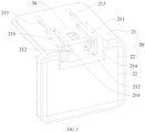
- the second structural member 20 is provided with plugging slots 211, one end of the plugging slot 211 having an opening, and the other end of the plugging slot 211 being provided with a blocking wall 212.
- one end of the plugging slot 211 in an extension direction thereof is provided with the opening, while the other end thereof is closed, and the blocking wall 212 is located on a slot wall of the plugging slot 211.
- Two plugging slots 211 are provided at an interval. It can be understood that the distance between the two plugging slots 211 is equal to the distance between the two plugging blocks 12.
- the two plugging blocks 12 are respectively slidably plugged in the two plugging slots 211 towards the two blocking walls 212.
- each of the plugging blocks 12 is at least partially accommodated in the corresponding plugging slot 211, and one end of the plugging block 12 facing the blocking wall 212 abuts against the blocking wall 212, so that movement of the plugging block 12 in a plugging sliding direction is restricted by the blocking wall 212.
- connection structure further comprises a limiting mechanism 30, and the limiting mechanism 30 is configured to detachably connect the base plate 11 to the second structural member 20, and restrain the two plugging blocks 12 from being separated from the two plugging slots 211 respectively in a direction away from the blocking walls 212. It can be understood that the limiting mechanism 30 can restrain the plugging blocks 12 from reversely sliding out of the plugging slots 211 in a direction away from a plugging direction, thereby improving the reliability of connection between the first structural member 10 and the second structural member 20.
- a first structural member 10 is provided with two plugging blocks 12 at an interval
- a second structural member 20 is provided with two plugging slots 211 at an interval
- the two plugging blocks 12 are respectively slidably plugged in the two plugging slots 211
- blocking walls 212 restrict movement of the two plugging blocks 12 in a plugging direction
- a limiting mechanism 30 restrains, in a direction away from the blocking walls 212, the plugging blocks 12 from sliding out of the corresponding plugging slots 211, so that the first structural member 10 and the second structural member 20 are not easily loosened, thereby improving the reliability of connection between the first structural member 10 and the second structural member 20, and thus improving the reliability of connection between a plug 101 and a power adapter 102.
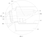
- the limiting mechanism 30 comprises an elastic arm 32 connected to the base plate 11, having an elastic restoring force and located between the two plugging blocks 12; a first engagement portion connected to the elastic arm 32; and a second engagement portion in snap fit with the first engagement portion and located on the second structural member 20, wherein the base plate 11 is provided with an avoidance groove 111 at the position corresponding to the elastic arm 32.
- the elastic arm 32 is also made of a plastic material, and has certain plasticity, so that the elastic arm can be elastically deformed by a predetermined amount relative to a plate surface of the base plate 11.
- the elastic arm 32 and the base plate 11 are integrally formed.
- the elastic arm 32 is elastically deformed in a direction away from the second structural member 20, and a free end of the elastic arm 32 moves towards the inside of the avoidance groove 111. After the two plugging blocks 12 abut against the two blocking walls 212, respectively, the elastic arm 32 is reset, and the first engagement portion is engaged with the second engagement portion.
- the two plugging blocks 12 can be restrained from sliding out of the plugging slots 211 in a direction away from the blocking walls 212, thereby improving the reliability of connection between the first structural member 10 and the second structural member 20.
- the elastic arm 32 presses the first engagement portion and the second engagement portion, thereby strengthening the engagement between the first engagement portion and the second engagement portion.
- the first engagement portion is a first snap block 33 arranged on the elastic arm 32 in a protruding manner
- the second engagement portion is a first snap slot 34 provided in the second structural member 20
- the surface of the first snap block 33 facing away from the blocking wall 212 is provided with a first stop wall 331, the first stop wall 331 being at least partially located in the first snap slot 34.
- the first stop wall 331 is substantially perpendicular to the direction in which the plugging block 12 is plugged in the plugging slot 211, and the first stop wall 331 abuts against a slot wall of the first snap slot 34 in the direction away from the blocking walls 212, so that under the combined action of the first stop wall 331 and the two blocking walls 212, the plugging block 12 is restrained from being separated from the corresponding plugging slot 211 in the plugging direction, thereby improving the reliability of connection between the first structural member 10 and the second structural member 20.
- the surface of the first snap block 33 facing the blocking wall 212 is provided with a first guide surface 332.
- the first guide surface 332 is inclined in the direction away from one of the blocking walls 212, and the first guide surface 332 can guide engagement of the first snap block 33 into the first snap slot 34, so as to improve convenience of plugging the plugging block 12 into the plugging slot 211.
- the elastic arm 32 is driven by an external force to undergo a predetermined amount of elastic deformation in the direction away from the second structural member 20, so that the first snap block 33 is disengaged from the first snap slot 34, and then the two plugging blocks 12 are driven to slide out of the two plugging slots 211, respectively, thereby facilitating disassembly/assembly of the first structural member 10 and the second structural member 20.
- the first engagement portion is a second snap slot provided in the elastic arm 32
- the second engagement portion is a second snap block arranged on the second structural member 20 in a protruding manner
- the surface of the second snap block facing away from the blocking wall 212 is provided with a second stop wall 331, the second stop wall 331 being at least partially located in the second snap slot.
- the second stop wall 331 is substantially perpendicular to the direction in which the plugging block 12 is plugged in the plugging slot 211, and the second stop wall 331 abuts against a slot wall of the second snap slot in the direction away from one of the blocking walls 212, so that under the combined action of the second stop wall 331 and the two blocking walls 212, the plugging block 12 is restrained from being separated from the corresponding plugging slot 211 in the plugging direction, thereby improving the reliability of connection between the second structural member 20 and the second structural member 20.
- the elastic arm 32 is driven by an external force to undergo a predetermined amount of elastic deformation in the direction away from the second structural member 20, so that the second snap block is disengaged from the second snap slot, and then the two plugging blocks 12 are driven to slide out of the two plugging slots 211, respectively, thereby facilitating disassembly/assembly of the first structural member 10 and the second structural member 20.
- the surface of the second snap block facing the blocking wall 212 is provided with a second guide surface.
- the second guide surface is inclined in the direction away from one of the blocking walls 212, and the second guide surface can guide engagement of the second snap block into the second snap slot, so as to improve convenience of plugging the plugging block 12 into the plugging slot 211.
- the limiting mechanism 30 further comprises a toggle piece 31, and the toggle piece 31 is connected to the free end of the elastic arm 32.
- a length direction of the toggle piece 31 is staggered with a length direction of the elastic arm 32, and the elastic arm 32 can be driven to elastically deform in the direction away from the second structural member 20 by manipulating the toggle piece 31 by hand.
- At least one of slot walls of at least one of the plugging slots 211 is provided with a first guide slot 214, a path extension direction of the first guide slot 214 is the same as a path extension direction of the plugging slot 211, and a first guide strip 13 matching the first guide slot 214 is arranged on the plugging block 12 at the position corresponding to the first guide slot 214 in a protruding manner.
- slot walls of the two plugging slots 211 are each provided with a first guide slot 214, and a first guide strip 13 is arranged on each plugging block 12 in a protruding manner.
- the two first guide slots 214 are in plugging fit with the two first guide strips 13, respectively, so that the plugging blocks 12 can be restrained from being separated from the corresponding plugging slots 211 in a direction perpendicular to the plugging direction, thereby improving the reliability of connection between the first structural member 10 and the second structural member.
- the two first guide strips 13 are both located between the two plugging blocks 12.
- a second guide strip is arranged on at least one of slot walls of at least one of the plugging slots 211 in a protruding manner, a length direction of the second guide strip is the same as a path extension direction of the plugging slot 211, and the plugging block 12 is provided with a second guide slot matching the second guide strip at the position corresponding to the second guide strip.
- a second guide strip is arranged on a slot wall of each of the two plugging slots 211 in a protruding manner, and each plugging block 12 is provided with a second guide slot.
- the two second guide slots are in plugging fit with the two second guide strips, respectively, so that the plugging blocks 12 can be restrained from being separated from the corresponding plugging slots 211 in the direction perpendicular to the plugging direction, thereby improving the reliability of connection between the second structural member 20 and the second structural member.
- the two second guide slots are both located between the two plugging blocks 12.
- the present application further provides a conversion apparatus 100, and the conversion apparatus 100 comprises a connection structure.
- the conversion apparatus 100 uses all the technical solutions of all the foregoing embodiments, the conversion apparatus also has all the beneficial effects brought by the technical solutions of the foregoing embodiments. Details are not described again herein.
- the conversion apparatus 100 further comprises a plug 101 and a power adapter 102 capable of being electrically connected to the plug 101, the base plate 11 is connected to the plug 101, and the second structural member 20 is connected to the power adapter 102.
- the plug 101 is electrically connected to the power adapter 102, and by electrically plugging the plug 101 into a power socket, the power adapter 102 can be indirectly electrically connected to the power plug 101. It can be understood that the power adapter 102 can be adapted to power sockets in different countries by replacing plugs 101 having different specification standards.
- the plug 101 is a Chinese standard plug, an American standard plug, a European standard plug, an Australian standard plug or a British standard plug.
- the Chinese standard plug is a plug 101 which meets the Chinese standard.
- the American standard plug is a plug 101 which meets the American standard.
- the European standard plug is a plug 101 which meets the European standard.
- the Australian standard plug is a plug 101 which meets the Australian standard.
- the British standard plug is a plug 101 which meets the British standard.
- a Korean standard plug is a plug 101 which meets the Korean standard.
- the power adapter 102 is further provided with a plurality of USB interfaces and/or a plurality of TYPE-C interfaces.
- the second structural member 20 comprises a side plate 22 and a cover plate 21, and the plugging slots 211 are provided in the cover plate 21 and extend to the side plate 22.
- a plate surface of the side plate 22 is arranged perpendicular to a plate surface of the cover plate 21, and both the side plate 22 and the cover plate 21 are connected to the power adapter 102.
- the power adapter 102 comprises electric pins 213 electrically connected to the plug 101, the electric pins 213 are rotatably arranged in the plugging slots 211, and the plugging block 12 is provided with an accommodating hole 124 for accommodating the electric pin 213.
- the power adapter 102 can be independently electrically connected to a corresponding power socket, thereby improving convenience of using the conversion apparatus 100.
Landscapes
- Connector Housings Or Holding Contact Members (AREA)
- Apparatus For Radiation Diagnosis (AREA)
- Coupling Device And Connection With Printed Circuit (AREA)
- Steering Control In Accordance With Driving Conditions (AREA)
Applications Claiming Priority (1)
| Application Number | Priority Date | Filing Date | Title |
|---|---|---|---|
| PCT/CN2022/078035 WO2023159497A1 (fr) | 2022-02-25 | 2022-02-25 | Structure de connexion et dispositif adaptateur |
Publications (2)
| Publication Number | Publication Date |
|---|---|
| EP4262032A4 EP4262032A4 (fr) | 2023-10-18 |
| EP4262032A1 true EP4262032A1 (fr) | 2023-10-18 |
Family
ID=85461439
Family Applications (1)
| Application Number | Title | Priority Date | Filing Date |
|---|---|---|---|
| EP22716844.0A Withdrawn EP4262032A1 (fr) | 2022-02-25 | 2022-02-25 | Structure de connexion et dispositif adaptateur |
Country Status (5)
| Country | Link |
|---|---|
| US (1) | US12341291B2 (fr) |
| EP (1) | EP4262032A1 (fr) |
| CN (1) | CN117099272A (fr) |
| TW (1) | TWM633424U (fr) |
| WO (1) | WO2023159497A1 (fr) |
Families Citing this family (1)
| Publication number | Priority date | Publication date | Assignee | Title |
|---|---|---|---|---|
| US20250141168A1 (en) * | 2023-11-01 | 2025-05-01 | Belkin International, Inc. | Interchangeable plug for a power adapter and methods for providing and using the same |
Family Cites Families (23)
| Publication number | Priority date | Publication date | Assignee | Title |
|---|---|---|---|---|
| US6086395A (en) * | 1998-08-02 | 2000-07-11 | Motorola, Inc. | Power transformer |
| US6270364B1 (en) * | 2000-11-20 | 2001-08-07 | Tongt-Huei Wang | Portable electrical adapter |
| JP2002198146A (ja) * | 2000-12-22 | 2002-07-12 | Mitsumi Electric Co Ltd | Acアダプタ用変換プラグ |
| TWI347714B (en) * | 2007-11-07 | 2011-08-21 | Delta Electronics Inc | Electronic device with replaceable plug |
| CN101986476A (zh) * | 2009-07-28 | 2011-03-16 | 鸿富锦精密工业(深圳)有限公司 | 电源插头 |
| CN201717433U (zh) * | 2010-03-12 | 2011-01-19 | 国琏电子(上海)有限公司 | 电源装置 |
| TWI433413B (zh) * | 2011-05-09 | 2014-04-01 | Wistron Corp | 延長線裝置 |
| CN102957034A (zh) * | 2011-08-29 | 2013-03-06 | 鸿富锦精密工业(深圳)有限公司 | 插座组合 |
| CN103378625B (zh) * | 2012-04-26 | 2017-01-25 | 富泰华工业(深圳)有限公司 | 移动电源 |
| CN202749568U (zh) * | 2012-06-01 | 2013-02-20 | 旭丽电子(广州)有限公司 | 插头装置及具有该插头装置的电子设备 |
| US9112326B2 (en) * | 2013-09-03 | 2015-08-18 | Leader Electronics Inc. | Power adapter with a combinational plug |
| TWI564697B (zh) * | 2015-11-05 | 2017-01-01 | 鴻海精密工業股份有限公司 | 電源適配器 |
| US10297965B1 (en) * | 2017-12-25 | 2019-05-21 | Mobileconn Technology Co., Ltd | Power supply device and power transformer with replaceable plug head |
| US10601194B1 (en) * | 2018-09-28 | 2020-03-24 | Min-Hung Chien | Electrical power adapter |
| US10996695B2 (en) * | 2018-09-28 | 2021-05-04 | Min-Hung Chien | Electrical power adapter |
| WO2020062197A1 (fr) * | 2018-09-30 | 2020-04-02 | 群智电子科技(东莞)有限公司 | Chargeur universel pour multiples pays à connexion stable et fiable |
| CN210744351U (zh) * | 2019-07-03 | 2020-06-12 | 深圳市永诺摄影器材股份有限公司 | 连接结构及电子器件 |
| US10797425B1 (en) * | 2019-10-09 | 2020-10-06 | Paul Zeng Universal Supplies, LLC | Compact travel adapter and extension cord |
| CN113131257B (zh) * | 2020-01-13 | 2024-10-29 | 深圳市永明尚德科技发展有限公司 | 多功能插头以及电源适配器 |
| WO2021184241A1 (fr) * | 2020-03-18 | 2021-09-23 | 广东高普达集团股份有限公司 | Adaptateur d'alimentation |
| WO2022032435A1 (fr) * | 2020-08-10 | 2022-02-17 | 广东高普达集团股份有限公司 | Adaptateur d'alimentation |
| CN213212552U (zh) * | 2020-11-05 | 2021-05-14 | 深圳市永明尚德科技发展有限公司 | 转换插头及插头组件 |
| TWI788071B (zh) * | 2021-10-28 | 2022-12-21 | 群光電能科技股份有限公司 | 具可分離插頭的電子裝置 |
-
2022
- 2022-02-25 CN CN202280000348.3A patent/CN117099272A/zh active Pending
- 2022-02-25 EP EP22716844.0A patent/EP4262032A1/fr not_active Withdrawn
- 2022-02-25 WO PCT/CN2022/078035 patent/WO2023159497A1/fr not_active Ceased
- 2022-06-16 TW TW111206348U patent/TWM633424U/zh unknown
- 2022-09-22 US US17/950,687 patent/US12341291B2/en active Active
Also Published As
| Publication number | Publication date |
|---|---|
| CN117099272A (zh) | 2023-11-21 |
| WO2023159497A1 (fr) | 2023-08-31 |
| EP4262032A4 (fr) | 2023-10-18 |
| US12341291B2 (en) | 2025-06-24 |
| US20230307869A1 (en) | 2023-09-28 |
| TWM633424U (zh) | 2022-10-21 |
Similar Documents
| Publication | Publication Date | Title |
|---|---|---|
| CN217469027U (zh) | 一种插头插座组件 | |
| EP4262032A1 (fr) | Structure de connexion et dispositif adaptateur | |
| US9859645B2 (en) | Connector including a terminal retainer | |
| CN104868318B (zh) | 电子卡连接器和移动终端 | |
| US8492017B2 (en) | Battery and holding structure for same | |
| CN208596826U (zh) | 一种电连接器壳体结构以及电连接器 | |
| WO2024094143A1 (fr) | Connecteur ayant une structure pré-fixe cpa | |
| CN217656118U (zh) | 一种插座 | |
| US8471147B2 (en) | Cover for electronic device | |
| CN202856002U (zh) | 电连接插座 | |
| CN219067372U (zh) | 一种方便接插且可自动退出的连接器 | |
| CN217062705U (zh) | 一种连接结构以及转换装置 | |
| CN218415259U (zh) | 适配器 | |
| CN204680832U (zh) | 电子卡连接器和移动终端 | |
| CN212277533U (zh) | 数据传输设备、显示控制卡和显示控制系统 | |
| CN223665706U (zh) | 插座 | |
| CN218334437U (zh) | 一种具有锁片保护机构的连接器 | |
| CN216648767U (zh) | 一种矩形连接器防脱机构 | |
| CN222785568U (zh) | 一种防脱插座组件 | |
| CN115810950B (zh) | 一种方便接插且可自动退出的连接器 | |
| CN222563035U (zh) | 按压解锁式电缆连接器 | |
| CN222301004U (zh) | 一种单联带防脱装置的iec输出插座 | |
| CN219304015U (zh) | 一种连接器及电子设备 | |
| CN220324797U (zh) | 结构改进的io模组 | |
| CN219576110U (zh) | 重载连接器插芯组 |
Legal Events
| Date | Code | Title | Description |
|---|---|---|---|
| STAA | Information on the status of an ep patent application or granted ep patent |
Free format text: STATUS: UNKNOWN |
|
| STAA | Information on the status of an ep patent application or granted ep patent |
Free format text: STATUS: THE INTERNATIONAL PUBLICATION HAS BEEN MADE |
|
| PUAI | Public reference made under article 153(3) epc to a published international application that has entered the european phase |
Free format text: ORIGINAL CODE: 0009012 |
|
| STAA | Information on the status of an ep patent application or granted ep patent |
Free format text: STATUS: REQUEST FOR EXAMINATION WAS MADE |
|
| STAA | Information on the status of an ep patent application or granted ep patent |
Free format text: STATUS: EXAMINATION IS IN PROGRESS |
|
| 17P | Request for examination filed |
Effective date: 20220426 |
|
| A4 | Supplementary search report drawn up and despatched |
Effective date: 20230711 |
|
| AK | Designated contracting states |
Kind code of ref document: A1 Designated state(s): AL AT BE BG CH CY CZ DE DK EE ES FI FR GB GR HR HU IE IS IT LI LT LU LV MC MK MT NL NO PL PT RO RS SE SI SK SM TR |
|
| 17Q | First examination report despatched |
Effective date: 20230929 |
|
| DAV | Request for validation of the european patent (deleted) | ||
| DAX | Request for extension of the european patent (deleted) | ||
| STAA | Information on the status of an ep patent application or granted ep patent |
Free format text: STATUS: THE APPLICATION IS DEEMED TO BE WITHDRAWN |
|
| 18D | Application deemed to be withdrawn |
Effective date: 20250902 |