EP4262037A1 - Stromkabel mit einer kabelverbindungswasserbarriere aus zinn oder zinnlegierung - Google Patents
Stromkabel mit einer kabelverbindungswasserbarriere aus zinn oder zinnlegierung Download PDFInfo
- Publication number
- EP4262037A1 EP4262037A1 EP23167558.8A EP23167558A EP4262037A1 EP 4262037 A1 EP4262037 A1 EP 4262037A1 EP 23167558 A EP23167558 A EP 23167558A EP 4262037 A1 EP4262037 A1 EP 4262037A1
- Authority
- EP
- European Patent Office
- Prior art keywords
- water barrier
- joint
- alloy
- cable section
- power cable
- Prior art date
- Legal status (The legal status is an assumption and is not a legal conclusion. Google has not performed a legal analysis and makes no representation as to the accuracy of the status listed.)
- Pending
Links
Images


Classifications
-
- H—ELECTRICITY
- H02—GENERATION; CONVERSION OR DISTRIBUTION OF ELECTRIC POWER
- H02G—INSTALLATION OF ELECTRIC CABLES OR LINES, OR OF COMBINED OPTICAL AND ELECTRIC CABLES OR LINES
- H02G15/00—Cable fittings
- H02G15/08—Cable junctions
- H02G15/18—Cable junctions protected by sleeves, e.g. for communication cable
-
- H—ELECTRICITY
- H02—GENERATION; CONVERSION OR DISTRIBUTION OF ELECTRIC POWER
- H02G—INSTALLATION OF ELECTRIC CABLES OR LINES, OR OF COMBINED OPTICAL AND ELECTRIC CABLES OR LINES
- H02G1/00—Methods or apparatus specially adapted for installing, maintaining, repairing or dismantling electric cables or lines
- H02G1/14—Methods or apparatus specially adapted for installing, maintaining, repairing or dismantling electric cables or lines for joining or terminating cables
-
- Y—GENERAL TAGGING OF NEW TECHNOLOGICAL DEVELOPMENTS; GENERAL TAGGING OF CROSS-SECTIONAL TECHNOLOGIES SPANNING OVER SEVERAL SECTIONS OF THE IPC; TECHNICAL SUBJECTS COVERED BY FORMER USPC CROSS-REFERENCE ART COLLECTIONS [XRACs] AND DIGESTS
- Y02—TECHNOLOGIES OR APPLICATIONS FOR MITIGATION OR ADAPTATION AGAINST CLIMATE CHANGE
- Y02A—TECHNOLOGIES FOR ADAPTATION TO CLIMATE CHANGE
- Y02A30/00—Adapting or protecting infrastructure or their operation
- Y02A30/14—Extreme weather resilient electric power supply systems, e.g. strengthening power lines or underground power cables
Definitions
- the present invention relates to power cables comprising a joint with a metallic water barrier and in particular, metallic water barrier materials for cable joints for use in high voltage cables for both land and submarine applications.
- Power cables for intermediate to high voltage ratings typically comprise an inner conductor and several layers provided radially outside the inner conductor, such as an electric insulation layer, a semiconductive shielding layer, an armouring layer and an outer sheathing.
- Power cables commonly comprise a sheath layer consisting of lead to be used as a radial water barrier. This relates to submarine power cables but is also relevant for other cables subjected to potential humid environment. Water and humidity are detrimental to electrical insulating materials for all power cables conducting electricity at medium and high voltages.
- Lead is a metal applicable as radial water barrier because of its relatively low melting point, the metal is soft and has a high malleability.
- its toxicity and negative environmental effects encourage the industry to find alternative solutions.
- the joint should obtain at least similar mechanical and electrical properties as compared to the rest of the cable to avoid the joint to become a weak link in the power cable.
- the joint should not have a considerably larger outer diameter than the outer diameter of the cable sections themselves.
- the joint must have a water barrier layer joining the water barrier layer of the two cable sections.
- the same material is used for the water barrier layer of the joint and the water barrier layers of the two joining cable sections.
- the material of the water barrier may be different from the water barrier material of the two joining cable sections.
- the joint may join cable sections with different water barrier materials.
- the joint may join cable sections with the same water barrier materials.
- one object of the present invention is to provide a power cable water barrier sheath for cable joints wherein the water barrier sheath of the cable joint is made of tin or a tin alloy.
- a power cable assembly comprising:
- the first water barrier and/or the second water barrier is/are a welded metal sheath or an extruded metal sheath or a laminate structure comprising a metal foil between to polymeric layers and wherein the metal is selected from either an Al/Al-alloy, a Cu/Cu-alloy, a Sn/Sn-alloy, a Ti/Ti-alloy or a Fe/Fe-alloy, a copper alloy such as CuNi, CuNiSi, CuZn, CuSn, CuAl, or a Fe-alloy such as 316 steel.
- the joint water barrier is made of commercially pure Sn, Sn-Cu or Sn-Sb.
- the joint water barrier is partially overlapping the first water barrier and/or the second water barrier.
- the joint water barrier is joined to the first water barrier and to the second water barrier by welding, soldering or by an adhesive. Thereby a first attachment between the first water barrier and the joint water barrier is formed together with a second attachment between the second water barrier and the joint water barrier.
- first reinforcement and the second reinforcement comprise a polyethylene-based adhesive.
- the joint water barrier is shaped as a sleeve.
- the power cable is a subsea power cable.
- the power cable is a land power cable.
- the power cable is a high voltage power cable.
- a method for joining a first water barrier layer of a first cable section and a second water barrier layer of a second cable section at a location of a joint comprising the steps of:
- the step of radially compressing the sleeve-shaped joint water barrier at the location of the joint comprises: rolling, hydrostatic forming or hydraulic forming.
- the steps of joining a first end of the joint water barrier to a first water barrier of the first cable section and joining a second end of the joint water barrier to a second water barrier of the second cable section are by welding, soldering or by an adhesive.
- a third aspect there is provided another method for joining a first water barrier layer of a first cable section and a second water barrier layer of a second cable section at a location of a joint, wherein the method comprises the steps of:
- the steps of joining a first end of the joint water barrier to a first water barrier of the first cable section and joining a second end of the joint water barrier to a second water barrier of the second cable section are formed by soldering or orbital friction stir welding.
- the methods of the second and the first aspects are suitable for preparing the power cable of the first aspects.
- step c) further comprises forming a first reinforcement by
- thermoplastic layer is laid radially around and covering at least the first reinforcement and the second reinforcement and heat treating the polyethylene based adhesive layer of the first reinforcement and the second reinforcement and the thermoplastic layer at a temperature thermally setting and melting together the adhesive layer and the thermoplastic layer.
- the first water barrier of the first cable section and/or the second water barrier of the second cable section is/are a welded metal sheath, an extruded metal sheath or a laminate structure comprising a metal foil between two polymeric layers and wherein the metal is selected from either an Al/Al-alloy, a Cu/Cu-alloy, a Sn/Sn-alloy, a Ti/Ti-alloy or a Fe/Fe-alloy, a copper alloy such as CuNi, CuNiSi, CuZn, CuSn, CuAl, or a Fe-alloy such as 316 steel.
- a joint water barrier for forming a water barrier of a joint joining a first cable section and a second cable section wherein the joint water barrier is sleeve-shaped and wherein the joint water barrier is made of a commercially pure Sn material or is made of Sn-alloy material.
- the present invention provides a power cable comprising a cable joint with a water barrier layer wherein the water barrier layer of the cable joint is made of tin or a tin alloy.
- Percentage solution may refer to: Mass fraction (chemistry) (or “% w/w” or “wt. %. "), for percent mass.
- high voltage refers to a voltage above 36kV such as in the range 50 kV to 800 kV.
- Water barrier layer for cable joints made of tin or a tin alloy
- tin is a soft, malleable and highly ductile metal with a relatively low melting temperature of around 232°C.
- tin and its alloys can have different crystal structures, wherein the alpha- tin crystal structure has a face-centred diamond-cubic structure and beta-tin has a body-centred tetragonal crystal structure.
- beta-tin can transform spontaneously into alpha-tin, a phenomenon known as "tin pest" or "tin disease".
- the tin and tin-alloys for use as a metallic water barrier over a joint are selected from commercially pure tin, a Sn-Cu alloy or a Sn-Sb alloy.
- Table 1 Commercially pure tin Sn [wt%] > 99.5 Unavoidable impurities [wt%] 0 - 0.5
- any percentage amount of a metal component in an alloy described herein is provided as a fraction of the weight of the metal per total weight of the alloy as a percentage, or [wt%].
- impurities may be present in the range from 0.0001%, 0.001%, 0.005% or 0.01% to 0.1%, 0.5%, 1% (wt) based on the total weight of the alloy and wherein each impurity does not exceed 0.5% by weight based on the total weight of the alloy. It will be appreciated such impurities may be present in the metals and alloys of the present invention without affecting or departing from the scope of the invention and comprises the following substances bismuth, antimony, lead and silver.
- the water barrier layer for a cable joint may be commercially pure Sn.
- the water barrier layer for a cable joint may be a Sn-0.7Cu alloy.
- the water barrier layer for a cable joint may be a Sn-5Sb alloy.
- Power cable comprising a cable joint
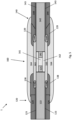
- a high voltage power cable assembly 1 comprising:
- water barrier layer for cable joints made of tin or a tin alloy water barrier layer for cable joints made of tin or a tin alloy.
- the water barriers of the first 23, 123 and the second 43, 143 water barriers may be similar or dissimilar.
- one of the first and second water barriers may be an extruded lead sheath or extruded Sn/Sn-alloy sheath typically applied in static cables or it may be of any other metal known to the skilled person to be suited for forming water barriers in power cables.
- the first water barrier may also, in example embodiments, be of the same metal as the second water barrier which is a water barrier made of a welded metal sheath or a laminate structure typically applied in dynamical cables, e.g.
- an Al/Al-alloy a Cu/Cu-alloy, a Sn/Sn-alloy, a Ti/Ti-alloy or a Fe/Fe-alloy.
- a copper alloy such as e.g. CuNi, CuNiSi, CuZn, CuSn, or CuAl, or an iron alloy such as e.g. 316 steel.
- the invention is not tied to any specific design of the conductor 21, 121, 41, 141 and may comprise one or more electric conductors where each conductor consists of either a single strand or a plurality of strands arranged in a bundle.
- each conductor consists of either a single strand or a plurality of strands arranged in a bundle.
- the space in between the strands of electrically conductive material may be occupied by a semiconducting filler compound.
- Each electric conductor is typically electrically insulated by a dielectric layer and electrically shielded by a semiconducting layer arranged radially around the conductor 22, 122, 42, 142.
- the first conductor 21, 121 is electrically connected to the second conductor 41, 141 by joining the first conductor 21, 121 and the second conductor 41, 141 directly to each other.
- the cable joint 60, 160 comprises a joint conductor 61, 161 for joining the first conductor 21, 121 and the second conductor 41, 141 to each other.
- the first electrically insulating layer 22, 122 comprises an inner semiconductive layer, an outer semiconductive layer and an intermediate insulating layer between the inner semiconductive layer and the outer semiconductive layer
- the second electrically insulating layer 42, 142 comprises an inner semiconductive layer, an outer semiconductive layer and an intermediate insulating layer between the inner semiconductive layer and the outer semiconductive layer
- the joint insulation layer 62, 162 comprises an inner semiconductive layer, an outer semiconductive layer and an intermediate insulating layer between the inner semiconductive layer and the outer semiconductive layer.
- the first power cable section 20, 120 comprises a first outer sheath 24, 124 radially outside of the first water barrier 23, 123 the second power cable section 40, 140 comprises a second outer sheath 44, 144 radially outside of the second water barrier 43, 143 and the joint 60, 160 comprises a joint over-sheath 64 radially outside of the joint water barrier 63, 163.
- the joint water barrier 63, 163 may be shaped as a sleeve.
- the power cable assembly 1 may have a joint water barrier 63, 163 that is partially overlapping the first water barrier 23, 123 and/or the second water barrier 43, 143.
- the joint water barrier 63, 163 may be joined to the first water barrier 23, 123 and to the second water barrier 43, 143 by welding, soldering or by an adhesive.
- the power cable assembly 1 may further comprise
- first reinforcement 138 and the second reinforcement 139 comprise a polyethylene-based adhesive.
- the polyethylene based adhesive is a linear low-density polyethylene which is commercially available under the trademark Yparex 9403 supplied by The Compound Company in Netherland.
- the polyethylene based adhesive is polyethylene based copolymers where the comonomer has a polar functionality such as carboxylic acid, ester, anhydride, epoxy, alcohol, thiol, amine, such as e.g.
- the adhesive may be provided in the form of an adhesive tape which is applied helically to form an adhesive layer of approx. 1.5 mm thickness.
- a method for joining a first water barrier layer 23, 123 of a first cable section 20, 120 and a second water barrier layer 43, 143 of a second cable section 40, 140 at a location of a joint 60, 160 comprising the steps of:
- the step of radially compressing the sleeve-shaped joint water barrier 63, 163 at the location of the joint 60, 160 comprises: rolling, hydrostatic forming or hydraulic forming.
- the steps of joining a first end of the joint water barrier 63 to a first water barrier 23 of the first cable section 20 and joining a second end of the joint water barrier 63 to a second water barrier 43 of the second cable section 40 are by welding, soldering or by an adhesive.
- a third aspect there is provided method for joining a first water barrier layer 23, 123 of a first cable section 20, 120 and a second water barrier layer 43, 143 of a second cable section 40, 140 at a location of a joint 60, 160, wherein the method comprises the steps of:
- the steps of joining a first end of the joint water barrier 63 to a first water barrier 23 of the first cable section 20 and joining a second end of the joint water barrier 63 to a second water barrier 43 of the second cable section 40 are formed by soldering or orbital friction stir welding.
- friction stir welding may also reduce the total length of the joints.
- Friction stir welding is a process where metal pieces are welded by transforming the metal at the site of the weld to a plasticised state by mechanically stirring the materials together under precisely controlled process conditions to form a high-integrity, full penetration welded joint. The friction is obtained by a rotating tool that plunges into the material at the site of the joint.
- FSW is particularly useful when joining dissimilar metal pieces with different melting points that are difficult to weld using conventional welding techniques.
- thermoplastic layer is laid radially around and covering at least the first reinforcement 138 and the second reinforcement 139 and a heat treating of the polyethylene based adhesive layer of the first reinforcement 138 and the second reinforcement 139 and of the thermoplastic layer is performed at a temperature thermally setting and melting together the adhesive layer and the thermoplastic layer.
- the next step in the formation of the reinforcing element comprises depositing a layer of a thermoplastic material on top of the adhesive layer.
- the thermoplastic layer may in one example embodiment be a high density polyethylene applied by extruding it into a tape which is applied helically over the polyethylene based adhesive layer to form an outer sheathing layer of a thickness aligning its outer diameter with the outer diameter of the outer sheathing of the power cable, i.e.
- thermoplastic layer makes a smooth transition at the interface between the thermoplastic layer and the outer sheathing of the power cable with no or only a relatively small height difference across the interface, which typically gives a thickness of the thermoplastic layer in the range of 1 to 5 mm, or in the range of 2 to 4 mm, or in the range of 3 to 3.5 mm.
- FIG. 5 An example of a typical process of joining power cables and forming the joint water barrier 163 and the reinforcing elements 138, 139 is schematically illustrated as shown in Fig. 5 .
- the first water barrier 23, 123 of the first cable section 20, 120 and/or the second water barrier 43, 143 of the second cable section 40, 140 is/are a welded metal sheath or a laminate structure comprising a metal foil between two polymeric layers, wherein the metal is selected from either an Al/Al-alloy, a Cu/Cu-alloy, a Sn/Sn-alloy, a Ti/Ti-alloy or a Fe/Fe-alloy, a copper alloy such as CuNi, CuNiSi, CuZn, CuSn, CuAl, or a Fe-alloy such as 316 steel.
- water barrier material that is also applicable as water barrier material for the first cable section 20 and the second cable section 40 are described above under section "water barrier layer for cable joints made of tin or a tin alloy”.
- the power cable may in one example embodiment further include an over-sheath 64, 164 laid radially and enveloping the joint water barrier 63, 163, such as shown schematically in Fig. 2 and Fig. 5 .
- Suitable materials for the over-sheath in form of a mantel are well known to the skilled person such as e.g. a shrinkage hose made of a thermosetting polymer, a polyethylene polymer such as e.g. chlorosulphanated polyethylene (CSP), etc.
- a joint water barrier 63, 163 for forming a water barrier of a joint 60, 160 joining a first cable section 20, 120 and a second cable section 40, 140 wherein the joint water barrier 63, 163 is sleeve-shaped and wherein the joint water barrier 63, 163 is made of a commercially pure Sn material or is made of Sn alloy material.
- Example 1 Simulated production and bending tests of cable joints wherein the joint is made of either SnSb5 alloy or SnCu0.7 alloy and joint connected to metal tube by swagging.
- Power cables may be subject to harsh environment such as drop in temperatures below 0°C. It is well known that tin may form tin pest at low temperatures in particular temperatures below -30 to -40 °C.
- Friction stir welding of two metal sheet samples wherein the two metal sheet samples where either made of SnSb5 or SnCu0.7 have been conducted using the following parameters for the rotating tool: RPM: 1500, Speed: 80, Needle depth: 2,3 and Angle: 2 degrees.
Landscapes
- Cable Accessories (AREA)
Applications Claiming Priority (1)
| Application Number | Priority Date | Filing Date | Title |
|---|---|---|---|
| EP22305524.5A EP4262036A1 (de) | 2022-04-12 | 2022-04-12 | Stromkabel mit einer kabelmuffenwasserbarriere aus zinn oder zinnlegierung |
Publications (1)
| Publication Number | Publication Date |
|---|---|
| EP4262037A1 true EP4262037A1 (de) | 2023-10-18 |
Family
ID=81389079
Family Applications (2)
| Application Number | Title | Priority Date | Filing Date |
|---|---|---|---|
| EP22305524.5A Withdrawn EP4262036A1 (de) | 2022-04-12 | 2022-04-12 | Stromkabel mit einer kabelmuffenwasserbarriere aus zinn oder zinnlegierung |
| EP23167558.8A Pending EP4262037A1 (de) | 2022-04-12 | 2023-04-12 | Stromkabel mit einer kabelverbindungswasserbarriere aus zinn oder zinnlegierung |
Family Applications Before (1)
| Application Number | Title | Priority Date | Filing Date |
|---|---|---|---|
| EP22305524.5A Withdrawn EP4262036A1 (de) | 2022-04-12 | 2022-04-12 | Stromkabel mit einer kabelmuffenwasserbarriere aus zinn oder zinnlegierung |
Country Status (2)
| Country | Link |
|---|---|
| US (1) | US12489286B2 (de) |
| EP (2) | EP4262036A1 (de) |
Cited By (1)
| Publication number | Priority date | Publication date | Assignee | Title |
|---|---|---|---|---|
| NO20240150A1 (en) * | 2024-02-19 | 2025-08-20 | Nexans | A method of jointing cables |
Families Citing this family (1)
| Publication number | Priority date | Publication date | Assignee | Title |
|---|---|---|---|---|
| EP4723403A1 (de) * | 2024-09-26 | 2026-04-08 | Nexans | Stromkabelanordnung, verfahren zum verbinden von ummantelungen und verwendung eines lötmaterials |
Citations (4)
| Publication number | Priority date | Publication date | Assignee | Title |
|---|---|---|---|---|
| US4016356A (en) * | 1973-09-10 | 1977-04-05 | Raychem Limited | Heat recoverable article |
| DE2745579A1 (de) * | 1977-10-11 | 1979-04-19 | Jung & Lindig Bleiind | Verbindungs- und abzweigmuffe fuer kabel, verfahren zu ihrer herstellung und verwendung eines zinnplattierten bleibleches zur muffenherstellung |
| US4518819A (en) * | 1981-07-30 | 1985-05-21 | Raychem Corporation | Clamp assembly for power cables |
| EP3971915A1 (de) * | 2020-09-18 | 2022-03-23 | Nexans | Mehrschichtige radiale wassersperre für schnelle herstellung |
Family Cites Families (2)
| Publication number | Priority date | Publication date | Assignee | Title |
|---|---|---|---|---|
| US9425605B2 (en) * | 2013-03-14 | 2016-08-23 | Tyco Electronics Corporation | Method for protecting a cable splice connection with a cover assembly |
| CA3024014C (en) * | 2016-05-13 | 2023-10-03 | Nkt Hv Cables Gmbh | Joint, termination or cross-connection arrangement for a cable and method for providing a joint, termination or cross-connection arrangement |
-
2022
- 2022-04-12 EP EP22305524.5A patent/EP4262036A1/de not_active Withdrawn
-
2023
- 2023-04-10 US US18/132,702 patent/US12489286B2/en active Active
- 2023-04-12 EP EP23167558.8A patent/EP4262037A1/de active Pending
Patent Citations (4)
| Publication number | Priority date | Publication date | Assignee | Title |
|---|---|---|---|---|
| US4016356A (en) * | 1973-09-10 | 1977-04-05 | Raychem Limited | Heat recoverable article |
| DE2745579A1 (de) * | 1977-10-11 | 1979-04-19 | Jung & Lindig Bleiind | Verbindungs- und abzweigmuffe fuer kabel, verfahren zu ihrer herstellung und verwendung eines zinnplattierten bleibleches zur muffenherstellung |
| US4518819A (en) * | 1981-07-30 | 1985-05-21 | Raychem Corporation | Clamp assembly for power cables |
| EP3971915A1 (de) * | 2020-09-18 | 2022-03-23 | Nexans | Mehrschichtige radiale wassersperre für schnelle herstellung |
Non-Patent Citations (2)
| Title |
|---|
| CORNELIUS, B ET AL.: "The phenomenon of tin pest: A review", MICROELECTRONICS RELIABILITY, vol. 79, 2017, pages 175 - 192, XP085265568, DOI: 10.1016/j.microrel.2017.10.030 |
| PLUMBRIDGE, WJ: "Tin pest issues in lead-free electronic solders", JOURNAL OF MATERIAL SCIENCE: MATERIALS IN ELECTRONICS, vol. 18, 2007, pages 307 - 318, XP019451021, DOI: 10.1007/s10854-006-9025-3 |
Cited By (2)
| Publication number | Priority date | Publication date | Assignee | Title |
|---|---|---|---|---|
| NO20240150A1 (en) * | 2024-02-19 | 2025-08-20 | Nexans | A method of jointing cables |
| NO349237B1 (en) * | 2024-02-19 | 2025-11-17 | Nexans | A method of jointing cables |
Also Published As
| Publication number | Publication date |
|---|---|
| US12489286B2 (en) | 2025-12-02 |
| EP4262036A1 (de) | 2023-10-18 |
| US20230378740A1 (en) | 2023-11-23 |
Similar Documents
| Publication | Publication Date | Title |
|---|---|---|
| EP4262037A1 (de) | Stromkabel mit einer kabelverbindungswasserbarriere aus zinn oder zinnlegierung | |
| US7154044B2 (en) | Flat cable conductor, method of making the same and flat cable using the same | |
| EP3786982B1 (de) | Kabelummantelung aus cunisi-legierung | |
| EP1209696B1 (de) | Elektrische Leitung | |
| US11791065B2 (en) | Multi-layer radial water barrier for rapid manufacture | |
| US12518893B2 (en) | Power or data transmission cable with metallic water barrier and process for manufacturing such a cable | |
| EP4002619A1 (de) | Verstärkte wasserbarriere über einer muffe | |
| EP4068309A1 (de) | Pe-hülle mit niedrigem widerstand mit kombinierten klebenden und mechanischen eigenschaften | |
| DE102014012489A1 (de) | Anschlussteil für Aluminiumleitungen | |
| EP4261851A1 (de) | Stromkabel mit wassersperre aus zinn oder zinnlegierung | |
| DE2715086A1 (de) | Schichtkoerper | |
| CN116741449A (zh) | 用于海底应用的动态电力电缆的防水材料 | |
| US8188010B2 (en) | Composite superconductive wire-material, manufacturing method of composite superconductive wire-material, and superconductive cable | |
| EP4141893A1 (de) | Radial und axial leitende wassersperranordnung | |
| US20240233979A1 (en) | Joint water barrier | |
| DE3425749A1 (de) | Aufbau von elektrischen kabeln | |
| JP2003086024A (ja) | Sn系めっき平角導体およびそれを用いたフラットケーブル | |
| EP4607541A1 (de) | Kabelmantel aus einer zinn-antimon-legierung | |
| EP4715845A1 (de) | Zink und zinklegierungen als kabelummantelung | |
| EP4723403A1 (de) | Stromkabelanordnung, verfahren zum verbinden von ummantelungen und verwendung eines lötmaterials | |
| US12573526B2 (en) | Power cable with metallic sheath joint | |
| US20240363264A1 (en) | Radially and longitudinally conductive water barrier assembly | |
| JP7420363B2 (ja) | はんだ継手 | |
| NO20210584A1 (en) | Welded conductors for power transmission cables | |
| Guruswamy | SOLDERS Introduction: Soldering major joining processes. Solder material material melting point parts being joined. molten solder between parts joined, completely wetting surfaces joined. Soldering process |
Legal Events
| Date | Code | Title | Description |
|---|---|---|---|
| PUAI | Public reference made under article 153(3) epc to a published international application that has entered the european phase |
Free format text: ORIGINAL CODE: 0009012 |
|
| STAA | Information on the status of an ep patent application or granted ep patent |
Free format text: STATUS: THE APPLICATION HAS BEEN PUBLISHED |
|
| AK | Designated contracting states |
Kind code of ref document: A1 Designated state(s): AL AT BE BG CH CY CZ DE DK EE ES FI FR GB GR HR HU IE IS IT LI LT LU LV MC ME MK MT NL NO PL PT RO RS SE SI SK SM TR |
|
| STAA | Information on the status of an ep patent application or granted ep patent |
Free format text: STATUS: REQUEST FOR EXAMINATION WAS MADE |
|
| 17P | Request for examination filed |
Effective date: 20240418 |
|
| RBV | Designated contracting states (corrected) |
Designated state(s): AL AT BE BG CH CY CZ DE DK EE ES FI FR GB GR HR HU IE IS IT LI LT LU LV MC ME MK MT NL NO PL PT RO RS SE SI SK SM TR |
|
| STAA | Information on the status of an ep patent application or granted ep patent |
Free format text: STATUS: EXAMINATION IS IN PROGRESS |
|
| 17Q | First examination report despatched |
Effective date: 20251205 |