EP4262095A1 - Dispositif de communication et son procédé de fonctionnement - Google Patents
Dispositif de communication et son procédé de fonctionnement Download PDFInfo
- Publication number
- EP4262095A1 EP4262095A1 EP22167808.9A EP22167808A EP4262095A1 EP 4262095 A1 EP4262095 A1 EP 4262095A1 EP 22167808 A EP22167808 A EP 22167808A EP 4262095 A1 EP4262095 A1 EP 4262095A1
- Authority
- EP
- European Patent Office
- Prior art keywords
- communication device
- uwb
- antenna
- communication
- selection unit
- Prior art date
- Legal status (The legal status is an assumption and is not a legal conclusion. Google has not performed a legal analysis and makes no representation as to the accuracy of the status listed.)
- Pending
Links
- 238000004891 communication Methods 0.000 title claims abstract description 144
- 238000000034 method Methods 0.000 title claims abstract description 33
- 238000004590 computer program Methods 0.000 claims abstract description 7
- 230000004807 localization Effects 0.000 claims description 21
- 238000010801 machine learning Methods 0.000 claims description 7
- 230000004044 response Effects 0.000 claims description 5
- 230000004927 fusion Effects 0.000 claims description 4
- 238000005516 engineering process Methods 0.000 description 17
- 238000005259 measurement Methods 0.000 description 13
- 230000008569 process Effects 0.000 description 12
- 230000008901 benefit Effects 0.000 description 6
- 230000010287 polarization Effects 0.000 description 4
- 238000012545 processing Methods 0.000 description 4
- 238000001228 spectrum Methods 0.000 description 4
- 230000008859 change Effects 0.000 description 3
- 238000013461 design Methods 0.000 description 3
- 230000003068 static effect Effects 0.000 description 3
- 230000001133 acceleration Effects 0.000 description 2
- 238000004458 analytical method Methods 0.000 description 2
- 238000011161 development Methods 0.000 description 2
- 230000000694 effects Effects 0.000 description 2
- 238000005265 energy consumption Methods 0.000 description 2
- 239000003999 initiator Substances 0.000 description 2
- 238000004519 manufacturing process Methods 0.000 description 2
- 230000009286 beneficial effect Effects 0.000 description 1
- 230000015556 catabolic process Effects 0.000 description 1
- 230000000295 complement effect Effects 0.000 description 1
- 230000001010 compromised effect Effects 0.000 description 1
- 238000006731 degradation reaction Methods 0.000 description 1
- 230000001419 dependent effect Effects 0.000 description 1
- 230000007613 environmental effect Effects 0.000 description 1
- 230000006870 function Effects 0.000 description 1
- 230000005484 gravity Effects 0.000 description 1
- 230000010354 integration Effects 0.000 description 1
- 238000000691 measurement method Methods 0.000 description 1
- 238000012544 monitoring process Methods 0.000 description 1
- 230000003287 optical effect Effects 0.000 description 1
- 239000004065 semiconductor Substances 0.000 description 1
Images


Classifications
-
- H—ELECTRICITY
- H04—ELECTRIC COMMUNICATION TECHNIQUE
- H04B—TRANSMISSION
- H04B7/00—Radio transmission systems, i.e. using radiation field
- H04B7/02—Diversity systems; Multi-antenna system, i.e. transmission or reception using multiple antennas
- H04B7/04—Diversity systems; Multi-antenna system, i.e. transmission or reception using multiple antennas using two or more spaced independent antennas
- H04B7/06—Diversity systems; Multi-antenna system, i.e. transmission or reception using multiple antennas using two or more spaced independent antennas at the transmitting station
- H04B7/0602—Diversity systems; Multi-antenna system, i.e. transmission or reception using multiple antennas using two or more spaced independent antennas at the transmitting station using antenna switching
- H04B7/0608—Antenna selection according to transmission parameters
-
- H—ELECTRICITY
- H04—ELECTRIC COMMUNICATION TECHNIQUE
- H04B—TRANSMISSION
- H04B1/00—Details of transmission systems, not covered by a single one of groups H04B3/00 - H04B13/00; Details of transmission systems not characterised by the medium used for transmission
- H04B1/38—Transceivers, i.e. devices in which transmitter and receiver form a structural unit and in which at least one part is used for functions of transmitting and receiving
-
- G—PHYSICS
- G01—MEASURING; TESTING
- G01C—MEASURING DISTANCES, LEVELS OR BEARINGS; SURVEYING; NAVIGATION; GYROSCOPIC INSTRUMENTS; PHOTOGRAMMETRY OR VIDEOGRAMMETRY
- G01C21/00—Navigation; Navigational instruments not provided for in groups G01C1/00 - G01C19/00
- G01C21/10—Navigation; Navigational instruments not provided for in groups G01C1/00 - G01C19/00 by using measurements of speed or acceleration
- G01C21/12—Navigation; Navigational instruments not provided for in groups G01C1/00 - G01C19/00 by using measurements of speed or acceleration executed aboard the object being navigated; Dead reckoning
- G01C21/16—Navigation; Navigational instruments not provided for in groups G01C1/00 - G01C19/00 by using measurements of speed or acceleration executed aboard the object being navigated; Dead reckoning by integrating acceleration or speed, i.e. inertial navigation
-
- H—ELECTRICITY
- H04—ELECTRIC COMMUNICATION TECHNIQUE
- H04B—TRANSMISSION
- H04B1/00—Details of transmission systems, not covered by a single one of groups H04B3/00 - H04B13/00; Details of transmission systems not characterised by the medium used for transmission
- H04B1/69—Spread spectrum techniques
- H04B1/7163—Spread spectrum techniques using impulse radio
-
- H—ELECTRICITY
- H04—ELECTRIC COMMUNICATION TECHNIQUE
- H04B—TRANSMISSION
- H04B7/00—Radio transmission systems, i.e. using radiation field
- H04B7/02—Diversity systems; Multi-antenna system, i.e. transmission or reception using multiple antennas
- H04B7/04—Diversity systems; Multi-antenna system, i.e. transmission or reception using multiple antennas using two or more spaced independent antennas
- H04B7/06—Diversity systems; Multi-antenna system, i.e. transmission or reception using multiple antennas using two or more spaced independent antennas at the transmitting station
- H04B7/0602—Diversity systems; Multi-antenna system, i.e. transmission or reception using multiple antennas using two or more spaced independent antennas at the transmitting station using antenna switching
-
- H—ELECTRICITY
- H04—ELECTRIC COMMUNICATION TECHNIQUE
- H04B—TRANSMISSION
- H04B7/00—Radio transmission systems, i.e. using radiation field
- H04B7/02—Diversity systems; Multi-antenna system, i.e. transmission or reception using multiple antennas
- H04B7/04—Diversity systems; Multi-antenna system, i.e. transmission or reception using multiple antennas using two or more spaced independent antennas
- H04B7/08—Diversity systems; Multi-antenna system, i.e. transmission or reception using multiple antennas using two or more spaced independent antennas at the receiving station
- H04B7/0802—Diversity systems; Multi-antenna system, i.e. transmission or reception using multiple antennas using two or more spaced independent antennas at the receiving station using antenna selection
- H04B7/0805—Diversity systems; Multi-antenna system, i.e. transmission or reception using multiple antennas using two or more spaced independent antennas at the receiving station using antenna selection with single receiver and antenna switching
-
- H—ELECTRICITY
- H04—ELECTRIC COMMUNICATION TECHNIQUE
- H04L—TRANSMISSION OF DIGITAL INFORMATION, e.g. TELEGRAPHIC COMMUNICATION
- H04L25/00—Baseband systems
- H04L25/02—Details ; arrangements for supplying electrical power along data transmission lines
- H04L25/0202—Channel estimation
- H04L25/0212—Channel estimation of impulse response
-
- H—ELECTRICITY
- H04—ELECTRIC COMMUNICATION TECHNIQUE
- H04L—TRANSMISSION OF DIGITAL INFORMATION, e.g. TELEGRAPHIC COMMUNICATION
- H04L41/00—Arrangements for maintenance, administration or management of data switching networks, e.g. of packet switching networks
- H04L41/16—Arrangements for maintenance, administration or management of data switching networks, e.g. of packet switching networks using machine learning or artificial intelligence
-
- H—ELECTRICITY
- H04—ELECTRIC COMMUNICATION TECHNIQUE
- H04B—TRANSMISSION
- H04B2201/00—Indexing scheme relating to details of transmission systems not covered by a single group of H04B3/00 - H04B13/00
- H04B2201/69—Orthogonal indexing scheme relating to spread spectrum techniques in general
- H04B2201/7163—Orthogonal indexing scheme relating to impulse radio
- H04B2201/71634—Applied to ranging
Definitions
- the present disclosure relates to a communication device. Furthermore, the present disclosure relates to a corresponding method of operating a communication device, and to a computer program for carrying out said method.
- Ultra-wideband (UWB) communication technology is a technology that uses a high signal bandwidth, in particular for transmitting digital data over a wide spectrum of frequency bands with very low power.
- UWB technology may use the frequency spectrum of 3.1 to 10.6 GHz and may feature a high-frequency bandwidth of more than 500 MHz and very short pulse signals, potentially capable of supporting high data rates.
- the UWB technology enables a high data throughput for communication devices and a high precision for the localization of devices.
- UWB technology may be used for so-called ranging operations, i.e., for determining the distance between communicating devices. Therefore, UWB technology may be used to advantage in various applications, such as automotive applications.
- a communication device comprising: an ultra-wideband (UWB) communication unit configured to carry out UWB communication with an external communication device; a plurality of antennas operatively coupled to said UWB communication unit, at least one inertial sensor; an antenna selection unit configured to select, based on an output of the inertial sensor, a specific antenna of said plurality of antennas for carrying out the UWB communication.
- UWB ultra-wideband
- the output of the inertial sensor is indicative of a movement of the communication device and/or an orientation of the communication device relative to the external communication device.
- the antenna selection unit is further configured to select the specific antenna by analyzing a channel impulse response (CIR) resulting from the UWB communication.
- CIR channel impulse response
- the antenna selection unit is further configured to select the specific antenna based on one or more of the following parameters related to the CIR: a first path amplitude; a maximum path amplitude; a ratio between the first path amplitude and maximum path amplitude; a time difference between the first path and the maximum path; an energy level of the first path; a mean excess delay value; an energy level of the first path and of the maximum path.
- the antenna selection unit is configured to select the specific antenna using a machine learning algorithm.
- the inertial sensor is a gyroscope, a magnetometer or an accelerometer.
- the antenna selection unit is configured to perform a sensor fusion algorithm to combine the outputs of said inertial sensors.
- the antenna selection unit is configured to select the specific antenna based on the combined outputs of the inertial sensors.
- the communication device is a mobile node in a localization system.
- a localization system comprises a communication device of the kind set forth and at least one external communication device, in particular an anchor node, configured to carry out ranging operations with the communication device.
- said anchor node comprises a plurality of anchor antennas and wherein the antenna selection unit is further configured to select, based on an output of the inertial sensor, a specific anchor antenna of the plurality of anchor antennas for carrying out the UWB communication.
- the communication device is configured to transmit data indicative of the specific anchor antenna selected by the antenna selection unit to the anchor node.
- a method of operating a communication device comprising an ultra-wideband, UWB, communication unit, a plurality of antennas operatively coupled to said UWB communication unit, at least one inertial sensor and an antenna selection unit, the method comprising: carrying out, by the UWB communication unit, UWB communication with an external communication device; selecting, by the antenna selection unit, a specific antenna of said plurality of antennas for carrying out the UWB communication, wherein said selecting is based on an output of the inertial sensor.
- a computer program comprising executable instructions which, when executed by a communication device, cause said communication device to carry out a method of the kind set forth.
- UWB communication technology is a technology that uses a high signal bandwidth, in particular for transmitting digital data over a wide spectrum of frequency bands with very low power.
- UWB technology may use the frequency spectrum of 3.1 to 10.6 GHz and may feature a high-frequency bandwidth of more than 500 MHz and very short pulse signals, potentially capable of supporting high data rates.
- the UWB technology enables a high data throughput for communication devices and a high precision for the localization of devices.
- UWB technology may be used for so-called ranging operations, i.e., for determining the distance between communicating devices. Therefore, UWB technology may be used to advantage in various applications, such as automotive applications.
- UWB technology - also referred to as impulse-radio ultra-wideband (IR-UWB) - is an RF communication technology that uses pulses having a short duration for data communication.
- IR-UWB technology An important feature of IR-UWB technology is that it can be used for secure and accurate distance measurements between two or more devices. Typical distance measurement methods are the so-called single-sided two-way ranging (SS-TWR) method and the double-sided two-way ranging (DS-TWR) method.
- SS-TWR single-sided two-way ranging
- DS-TWR double-sided two-way ranging
- UWB technology has an accurate distance measurement capability, it may be used to advantage in access systems in which the position of devices should be determined to enable access to an object.
- a vehicle access system may comprise a user's smart device (e.g., key fob) and another smart device (e.g., an anchor embedded in the vehicle).
- the user's smart device must have a predefined range relative to the other smart device. Therefore, UWB transceivers are typically configured to operate in a ranging mode.
- UWB technology may be used for accessing a building or a predefined space within a building.
- UWB frames i.e., UWB signals
- SS-TWR operation which may also be referred to as a ping-pong operation
- CIRs channel impulse responses
- timestamps will be generated based on the CIRs on both devices, and those timestamps are exchanged.
- a time of flight (ToF) is calculated based on the timestamps and a range (i.e., a distance) is calculated based on the ToF.
- a DS-TWR operation may be carried out (which may also be referred to as a ping-pong-ping operation).
- the angle-of-arrival (AoA) mode of operation is similar to the ranging mode, but it involves at least two antennas on one device.
- two phase values associated with at least two CIRs are calculated on one device.
- a phase difference of arrival (PDoA) is calculated based on the two-phase values, and an AoA is calculated based on the PDoA.
- the AoA mode of operation may facilitate a more accurate determination of the position of an object and may thus complement ranging operations performed in the ranging mode.
- the ranging mode of operation may therefore be extended to include the AoA mode of operation, in the sense that when a device operates in the ranging mode, it may optionally perform additional operations which are typically performed in the AoA mode of operation.
- a channel impulse response as determined by a responder using a received UWB frame, can be used to determine not only the distance (i.e., the range) to an initiator but also the angle of arrival of the incoming radio-frequency (RF) wave from the initiator, which allows the system to use both range and angle for precise localization.
- RF radio-frequency
- the format of UWB frames is defined in the technical standard 802.15.4z-2020 ( IEEE Standard for Low-Rate Wireless Networks, Amendment 1: Enhanced Ultra Wideband (UWB) Physical Layers (PHYs) and Associated Ranging Techniques ).
- UWB-based localization for vehicle access can suffer from multipath effects (i.e., signal reflections) and attenuation due to environmental factors. For this reason, devices with multiple antennas have been developed. In such devices, the antennas can be placed in different locations and eventually with different polarization. This may result in an advantage, since the signal path to each antenna is different and one antenna can perform better than the other.
- a problem with this configuration is that, in order to achieve optimal results, it may be necessary to use all antennas to communicate, and then choose which is the best one. This, in turn, increases the amount of energy and time needed to perform a localization task, because either multiple communications sessions should be performed, or multiple receivers should be active simultaneously.
- the presently disclosed device and method facilitate selecting a specific antenna, from a set of available antennas, which results in a more accurate distance measurement (i.e., ranging result) compared to the other antennas included in said set.
- a more accurate distance measurement i.e., ranging result
- the amount of energy and time needed to perform a localization task does not increase significantly.
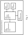
- Fig. 1 shows an illustrative embodiment of a communication device 100.
- the communication device 100 includes a UWB communication unit 102, a plurality of antennas 104, 106, an inertial sensor 108 and an antenna selection unit 110.
- the UWB communication unit 102 is configured to carry out UWB communication with an external communication device (not shown). It is noted that the term “external” refers to the fact that the external communication device is not included in the communication device 100.
- the plurality of antennas 104, 106 is operatively coupled to the UWB communication unit 102.
- the antenna selection unit 110 is configured to select, based on an output of the inertial sensor, a specific antenna of said plurality of antennas 104, 106 for carrying out the UWB communication. By taking into account the output of the inertial sensor, an appropriate antenna may be selected for carrying out the UWB communication.
- the output of the inertial sensor is indicative of a movement of the communication device and/or an orientation of the communication device relative to the external communication device.
- the selection of an appropriate antenna is further facilitated.
- the movement and/or orientation of the communication device may negatively affect the quality of the UWB communication between the communication device and the external communication device. If the antenna selection is based, at least partially, on the movement and/or orientation of the communication device, then a more appropriate antenna may be selected compared to a scenario in which said movement and/or orientation is not taken into account.
- the antenna selection unit is further configured to select the specific antenna by analyzing a channel impulse response (CIR) resulting from the UWB communication. In this way, the selection of a suitable antenna may be further facilitated.
- the antenna selection unit is further configured to select the specific antenna based on one or more of the following parameters related to the CIR: a first path amplitude; a maximum path amplitude; a ratio between the first path amplitude and maximum path amplitude; a time difference between the first path and the maximum path; an energy level of the first path; a mean excess delay value; an energy level of the first path and of the maximum path.
- the antenna selection unit is configured to select the specific antenna using a machine learning algorithm. In this way, the antenna selection can be optimized more easily in applications such as vehicle access, in which the environment surrounding the vehicle may frequently change.
- the term “maximum path” refers to the bin or tap in the CIR with the highest absolute value. Since CIRs are complex-valued, the maximum path may be defined as the index of the tap with the highest value sqrt (R 2 + I 2 ) in the CIR, wherein sqrt denotes the square root function, R denotes the real part of the complex-valued CIR, and I denotes the imaginary part of the complex-valued CIR.
- first path energy refers to the absolute sum of the taps in the CIR between the local minima before and after the detected first path tap.
- maximum path energy refers the absolute sum of the taps between the local minima before and after the detected maximum path tap.
- the excess delay interval is the range in the CIR that is of interest (i.e., the range which contains information different from noise). This interval may be defined by using a threshold relative to the detected first path, or it may be defined by a user.
- the inertial sensor is a gyroscope, a magnetometer or an accelerometer.
- these types of inertial sensor may provide an accurate indication of the movement and/or orientation of the communication device.
- a gyroscope is typically configured to track rotatory movements.
- a magnetometer measures the direction of the magnetic field, which provides an absolute orientation with regard to the magnetic field of the earth.
- An accelerometer is used for tracking linear accelerations.
- the communication device may include a so-called inertial measurement unit (IMU), which typically contains a gyroscope, a magnetometer and an accelerometer.
- IMU inertial measurement unit
- the antenna selection unit is configured to perform a sensor fusion algorithm to combine the outputs of said inertial sensors. Furthermore, the antenna selection unit may be configured to select the specific antenna based on the combined outputs of the inertial sensors. In this way, a more accurate indication of the movement and/or orientation of the communication device may be used for the antenna selection, compared to a scenario in which only the output of a single inertial sensor is used.
- the communication device is a mobile node in a localization system.
- a localization system comprises a communication device of the kind set forth and at least one external communication device, in particular an anchor node, configured to carry out ranging operations with the communication device. Since the antenna selection in said localization system is based, at least partially, on the output of an inertial sensor included in the communication device, more accurate ranging operations may be performed.
- the anchor node comprises a plurality of anchor antennas and the antenna selection unit is further configured to select, based on an output of the inertial sensor, a specific anchor antenna of the plurality of anchor antennas for carrying out the UWB communication.
- the accuracy of the ranging operations may be further increased, because the most appropriate pair of antennas may be selected for the UWB communication (i.e., the most appropriate combination of anchor node antenna and mobile node antenna).
- the communication device is configured to transmit data indicative of the specific anchor antenna selected by the antenna selection unit to the anchor node.
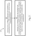
- Fig. 2 shows an illustrative embodiment of a method 200 of operating a communication device.
- the method 200 comprises the following steps.
- a UWB communication unit included in a communication device carries out UWB communication with an external communication device.
- an antenna selection unit included in the communication device selects a specific antenna of a plurality of antennas for carrying out the UWB communication, wherein said selecting is based on an output of an inertial sensor included in the communication.
- an appropriate antenna may be selected for carrying out the UWB communication.
- the most appropriate antenna may be the antenna that most likely results in the most accurate distance estimation, among the available antennas.
- information from other sensors in the mobile node can be used for the antenna choice.
- an inertial sensor such as an accelerometer, gyroscope and magnetometer, may provide information on the orientation and movements of the mobile node. This information may support the decision on which antenna to select on the side of the mobile node and on the side of the anchor nodes (as integrated in a vehicle, for example).
- Fig. 3 shows an illustrative embodiment of a localization system 300.
- the localization system 300 includes a vehicle 308 comprising a plurality of UWB-enabled anchor nodes 310, 312, 314, 316, 318.
- the localization system 300 includes an UWB-enabled mobile node 302 that should be localized by the vehicle 308.
- one or more of the UWB-enabled anchor nodes 310, 312, 314, 316, 318 carry out UWB communication with a UWB communication unit 304 included in the UWB-enabled mobile node 302.
- the UWB-enabled mobile node 302 also includes an IMU 306, by means of which the movement and/or orientation of the UWB-enabled mobile node 302 can be determined.
- the UWB-enabled mobile node 302 further includes an antenna selection unit (not shown) which is configured to select an antenna, from a plurality of antennas coupled to the UWB communication unit 304, based on an output of the IMU 306.
- the antenna selection unit may select said antenna based on other input, such as a result of an analysis of a CIR and/or parameters related to the CIR resulting from the ranging sessions.
- the multiple antennas may be either connected to a single receiver through a switch, to an integrated circuit (IC) with multiple receiver (RX) ports or to multiple UWB receiver ICs.
- multi-antenna devices has been shown to be beneficial in some scenarios for car access when the line-of-sight communication is compromised.
- the human body or other objects in the vicinity of the car can significantly attenuate the signal strength of UWB packets.
- a mobile node is randomly oriented, then a polarization mismatch may occur between transmit and receive antennas, resulting in further signal quality degradation. This effect may be mitigated by using antennas with different polarization.
- the use of multiple antennas may increase the energy consumption of the devices.
- the multi-antenna communication may be performed in parallel (in which case the devices require multiple receive blocks) or in sequence (in which case multiple messages should be sent, which also increases the measurement time). By selecting the antenna used for a localization task at least partially in dependence on an output of the IMU 306, the energy consumption of the devices may be kept at an acceptable level.
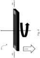
- Fig. 4 shows an illustrative embodiment of a mobile node 400.
- the mobile node 400 comprises two antennas 402, 404.
- the output of an inertial sensor (not shown) may be used to select an appropriate antenna for a ranging session, among the two available antennas 402, 404.
- an ambiguity may be present in the orientation of the antennas 402, 404. Therefore, the analysis of the CIR or features of the CIR (i.e., parameters related to the CIR) may be used to facilitate computing the correct orientation of the mobile node 400 relative to the anchor nodes.
- the inertial sensor may be a gyroscope, a magnetometer or an accelerometer.
- An accelerometer may be capable of sensing static and dynamic forces of acceleration. Static forces include gravity, while dynamic forces can include vibrations and movement.
- a gyroscope is a device used for measuring or maintaining orientation and angular velocity.
- a magnetometer may be capable of measuring a magnetic field or magnetic dipole moment. Different types of magnetometers may measure the direction, strength, or relative change of a magnetic field at a particular location.
- Fig. 5 shows an illustrative embodiment of an initial antenna selection process 500.
- the initial antenna selection process 500 includes the following steps: ranging 502 using all mobile node antennas, collecting 504 CIR or CIR features, estimating 506 mobile-node to vehicle orientation, and deciding 508 on an optimal antenna couple.
- a mobile node e.g., a key fob or mobile phone
- the location of a mobile node may have to be determined several times, such that the mobile node can be tracked. For instance, it should be determined whether the mobile node is approaching the car or moving away from the car.
- the mobile node uses information on its orientation relative to the car. Using this information, an antenna may be selected that has an optimal polarization, avoiding interference by obstacles.
- a measurement may be performed using all the available antennas in the mobile node. This allows to collect the CIR and other signal quality indicators for each antenna in the mobile node. For example, one or more of the following parameters may be used for this purpose: a first path amplitude, a maximum path amplitude, a ratio between the first path amplitude and maximum path amplitude, a time difference between the first path and the maximum path, an energy level of the first path, a mean excess delay value, and an energy level of the first path and of the maximum path. This information may then be used to identify the best antenna couple, in the sense that the relative orientation of the mobile node may be determined, as well as the presence of obstacles between the mobile node and the car.
- the CIR may provide information about the wireless propagation channel between the transmitter and receiver, in order to determine the amount of reflections as well as the amount of obstacles.
- This may be implemented using a machine learning algorithm trained to identify the best antenna, or using an analytical algorithm.
- the machine learning algorithm may be more suitable in applications such as car access, in which the environment may change significantly, and new obstructions or signal paths may affect which is the most suitable antenna couple.
- the machine learning algorithm may be trained prior to the system deployment in a controlled environment. Alternatively, a reinforced learning algorithm may be used, in which case the initial ranging with all available antennas may be used to calculate the rewards and penalties and the model may be updated accordingly.
- Fig. 6 shows an illustrative embodiment of a subsequent antenna selection process 600.
- the subsequent antenna selection process 600 includes the following steps: monitoring 602 the IMU, estimating 604 the mobile-node to vehicle orientation, deciding 606 on the optimal antenna couple, informing 608 the vehicle on the antenna selection, and ranging and analyzing 610 the CIR.
- one or more inertial sensors in the mobile node may be used to monitor its movement and orientation, and UWB ranging measurements may be carried out to track its location. More specifically, inertial sensors such as a magnetometer, accelerometer and gyroscope may provide information on how much the mobile node has been moved, and how its orientation has changed.
- Such information may be generated using a sensor fusion algorithm (e.g., an extended Kalman Filter) or by means of time integration of gyroscope or accelerometer data. If the mobile node does not have a full IMU, a simpler algorithm may be used, which takes for example only accelerometer data as input.
- a sensor fusion algorithm e.g., an extended Kalman Filter
- the algorithm may only check if a movement has occurred, and if this movement exceeds a predefined threshold a new ranging measurement may be performed. Since the decision on which antenna couple to use is taken by the mobile node, the information on the appropriate antenna to use may be transmitted to the vehicle in case the vehicle's anchors are also equipped with multiple antennas. This information may be transmitted either through an out-of-band communication channel or as the first UWB message during a ranging session. It is noted that the mobile node may be enabled to take the decision on which antenna couple to use by performing an initial setup process, which may be executed, for example, when the mobile node is being coupled to the vehicle. During that process, the mobile node may receive setup data containing information about the infrastructure of the vehicle.
- the mobile node may receive setup data indicative of the available anchor nodes and their antennas. Since this infrastructure typically remains unchanged, the mobile node may store the setup data, in order to use the information contained therein for the selection of the anchor antennas. Also, for subsequent ranging measurements, the CIR may be analyzed to check if the selected antenna is the most appropriate one. Similar to the initial antenna selection, this may be done either by means of a machine learning algorithm, or using an analytical algorithm that processes one or more CIR features or the entire CIR.
- the systems and methods described herein may at least partially be embodied by a computer program or a plurality of computer programs, which may exist in a variety of forms both active and inactive in a single computer system or across multiple computer systems.
- they may exist as software program(s) comprised of program instructions in source code, object code, executable code or other formats for performing some of the steps.
- Any of the above may be embodied on a computer-readable medium, which may include storage devices and signals, in compressed or uncompressed form.
- the term "computer” refers to any electronic device comprising a processor, such as a general-purpose central processing unit (CPU), a specific-purpose processor or a microcontroller.
- a computer is capable of receiving data (an input), of performing a sequence of predetermined operations thereupon, and of producing thereby a result in the form of information or signals (an output).
- the term "computer” will mean either a processor in particular or more generally a processor in association with an assemblage of interrelated elements contained within a single case or housing.
- processor or “processing unit” refers to a data processing circuit that may be a microprocessor, a co-processor, a microcontroller, a microcomputer, a central processing unit, a field programmable gate array (FPGA), a programmable logic circuit, and/or any circuit that manipulates signals (analog or digital) based on operational instructions that are stored in a memory.
- memory refers to a storage circuit or multiple storage circuits such as read-only memory, random access memory, volatile memory, non-volatile memory, static memory, dynamic memory, Flash memory, cache memory, and/or any circuit that stores digital information.
- a "computer-readable medium” or “storage medium” may be any means that can contain, store, communicate, propagate, or transport a computer program for use by or in connection with the instruction execution system, apparatus, or device.
- the computer-readable medium may be, for example but not limited to, an electronic, magnetic, optical, electromagnetic, infrared, or semiconductor system, apparatus, device, or propagation medium.
Landscapes
- Engineering & Computer Science (AREA)
- Computer Networks & Wireless Communication (AREA)
- Signal Processing (AREA)
- Remote Sensing (AREA)
- Radar, Positioning & Navigation (AREA)
- Medical Informatics (AREA)
- Databases & Information Systems (AREA)
- Evolutionary Computation (AREA)
- Computer Vision & Pattern Recognition (AREA)
- Software Systems (AREA)
- Artificial Intelligence (AREA)
- Power Engineering (AREA)
- Automation & Control Theory (AREA)
- Physics & Mathematics (AREA)
- General Physics & Mathematics (AREA)
- Mobile Radio Communication Systems (AREA)
- Position Fixing By Use Of Radio Waves (AREA)
Priority Applications (3)
| Application Number | Priority Date | Filing Date | Title |
|---|---|---|---|
| EP22167808.9A EP4262095A1 (fr) | 2022-04-12 | 2022-04-12 | Dispositif de communication et son procédé de fonctionnement |
| US18/124,295 US12255712B2 (en) | 2022-04-12 | 2023-03-21 | Communication device and method of operation |
| CN202310298720.XA CN116915294A (zh) | 2022-04-12 | 2023-03-24 | 通信装置和操作方法 |
Applications Claiming Priority (1)
| Application Number | Priority Date | Filing Date | Title |
|---|---|---|---|
| EP22167808.9A EP4262095A1 (fr) | 2022-04-12 | 2022-04-12 | Dispositif de communication et son procédé de fonctionnement |
Publications (1)
| Publication Number | Publication Date |
|---|---|
| EP4262095A1 true EP4262095A1 (fr) | 2023-10-18 |
Family
ID=81580135
Family Applications (1)
| Application Number | Title | Priority Date | Filing Date |
|---|---|---|---|
| EP22167808.9A Pending EP4262095A1 (fr) | 2022-04-12 | 2022-04-12 | Dispositif de communication et son procédé de fonctionnement |
Country Status (3)
| Country | Link |
|---|---|
| US (1) | US12255712B2 (fr) |
| EP (1) | EP4262095A1 (fr) |
| CN (1) | CN116915294A (fr) |
Families Citing this family (2)
| Publication number | Priority date | Publication date | Assignee | Title |
|---|---|---|---|---|
| US11418231B2 (en) | 2020-10-19 | 2022-08-16 | Hyundai Mobis Co., Ltd. | UWB system |
| US12555928B2 (en) * | 2023-02-27 | 2026-02-17 | Hewlett-Packard Development Company, L.P. | Antenna switching |
Citations (6)
| Publication number | Priority date | Publication date | Assignee | Title |
|---|---|---|---|---|
| CN111669208A (zh) * | 2020-05-29 | 2020-09-15 | 北京小米移动软件有限公司 | 天线选择方法及第一电子设备、存储介质 |
| US20200348406A1 (en) * | 2019-04-30 | 2020-11-05 | Robert Bosch Gmbh | Ultra-wideband intelligent sensing system and method |
| WO2021029617A1 (fr) * | 2019-08-13 | 2021-02-18 | 주식회사 아모센스 | Dispositif de mesure de position utilisant des antennes uwb |
| EP3848918A1 (fr) * | 2020-01-08 | 2021-07-14 | Nxp B.V. | Système et procédé de commande de dispositifs électroniques |
| EP3886468A1 (fr) * | 2020-03-26 | 2021-09-29 | Nxp B.V. | Localisation de porte-clés à l'intérieur d'un véhicule |
| US20210399761A1 (en) * | 2020-06-17 | 2021-12-23 | Nxp B.V. | Communication device and method of operating the same |
Family Cites Families (19)
| Publication number | Priority date | Publication date | Assignee | Title |
|---|---|---|---|---|
| US5561673A (en) | 1993-04-16 | 1996-10-01 | Matsushita Electric Industrial Co., Ltd. | Antenna switched diversity reciever |
| KR19990009325A (ko) | 1997-07-09 | 1999-02-05 | 윤종용 | 듀플렉서를 제거한 안테나 전환 다이버시티 장치 및 방법 |
| KR100270227B1 (ko) | 1997-08-18 | 2000-10-16 | 비센트 비.인그라시아 | 적응 기준 레벨을 갖는 저잡음 안테나 스위치 다이버시티장치 |
| JP2928224B1 (ja) | 1998-02-26 | 1999-08-03 | 静岡日本電気株式会社 | アンテナ切替ダイバーシティ受信装置及び受信方法 |
| DE10210238B4 (de) | 2002-03-08 | 2004-04-22 | Advanced Micro Devices, Inc., Sunnyvale | Geschaltete Kombinationsantennendiversitäts-Technik |
| WO2006120250A2 (fr) | 2005-05-13 | 2006-11-16 | Fractus, S.A. | Systeme a diversite d'antenne et composant d'antenne a fente |
| US9007275B2 (en) | 2006-06-08 | 2015-04-14 | Fractus, S.A. | Distributed antenna system robust to human body loading effects |
| CA2731034A1 (fr) | 2008-06-30 | 2010-01-14 | Sirius Xm Radio Inc. | Interface entre un systeme d'antennes a diversite commutee et un recepteur radio numerique |
| TWI452861B (zh) | 2010-10-08 | 2014-09-11 | Realtek Semiconductor Corp | 天線分集裝置與天線分集方法 |
| US20130051258A1 (en) | 2011-02-18 | 2013-02-28 | Chien-Jen Huang | Method of Controlling Receive Diversity for Battery Lifetime Improvement and Related Communication Device |
| US9148852B2 (en) | 2013-03-12 | 2015-09-29 | Qualcomm Incorporated | Method and apparatus for controlling receive diversity on a wireless device |
| DE102015106405A1 (de) | 2015-04-27 | 2016-10-27 | Intel IP Corporation | Verfahren und vorrichtungen auf der basis vondynamischer empfangsdiversität |
| US9961600B2 (en) | 2016-06-30 | 2018-05-01 | Qualcomm Incorporated | Techniques for employing antenna switched diversity in wireless communications |
| US20180132116A1 (en) * | 2016-10-26 | 2018-05-10 | Invensense Inc. | Systems and methods for motion assisted communication |
| US10595165B2 (en) * | 2018-07-25 | 2020-03-17 | Cisco Technology, Inc. | Device location tracking with tag antenna switching |
| EP3686623A1 (fr) | 2019-01-24 | 2020-07-29 | Nxp B.V. | Procédés permettant de faciliter la détermination d'une position relative |
| FI20205781A1 (en) * | 2020-08-04 | 2022-02-05 | Nokia Technologies Oy | MACHINE LEARNING BASED COUPLING OF AN ANTENNA PANEL |
| US11711782B2 (en) * | 2020-10-07 | 2023-07-25 | Qualcomm Incorporated | Anchor selection for UE positioning |
| US11418231B2 (en) * | 2020-10-19 | 2022-08-16 | Hyundai Mobis Co., Ltd. | UWB system |
-
2022
- 2022-04-12 EP EP22167808.9A patent/EP4262095A1/fr active Pending
-
2023
- 2023-03-21 US US18/124,295 patent/US12255712B2/en active Active
- 2023-03-24 CN CN202310298720.XA patent/CN116915294A/zh active Pending
Patent Citations (6)
| Publication number | Priority date | Publication date | Assignee | Title |
|---|---|---|---|---|
| US20200348406A1 (en) * | 2019-04-30 | 2020-11-05 | Robert Bosch Gmbh | Ultra-wideband intelligent sensing system and method |
| WO2021029617A1 (fr) * | 2019-08-13 | 2021-02-18 | 주식회사 아모센스 | Dispositif de mesure de position utilisant des antennes uwb |
| EP3848918A1 (fr) * | 2020-01-08 | 2021-07-14 | Nxp B.V. | Système et procédé de commande de dispositifs électroniques |
| EP3886468A1 (fr) * | 2020-03-26 | 2021-09-29 | Nxp B.V. | Localisation de porte-clés à l'intérieur d'un véhicule |
| CN111669208A (zh) * | 2020-05-29 | 2020-09-15 | 北京小米移动软件有限公司 | 天线选择方法及第一电子设备、存储介质 |
| US20210399761A1 (en) * | 2020-06-17 | 2021-12-23 | Nxp B.V. | Communication device and method of operating the same |
Also Published As
| Publication number | Publication date |
|---|---|
| US20230327720A1 (en) | 2023-10-12 |
| US12255712B2 (en) | 2025-03-18 |
| CN116915294A (zh) | 2023-10-20 |
Similar Documents
| Publication | Publication Date | Title |
|---|---|---|
| Conti et al. | Soft information for localization-of-things | |
| CN109218282B (zh) | 用于超宽带系统的脉冲成形互操作协议 | |
| EP3417309B1 (fr) | Détection de mouvement sur la base d'émissions sans fil répétées | |
| US12323943B2 (en) | System and method for facilitating localizing an external object | |
| US20150189619A1 (en) | Method, apparatus, and computer program product for secure distance bounding based on direction measurement | |
| US20090047976A1 (en) | Radio positioning system | |
| US12255712B2 (en) | Communication device and method of operation | |
| EP4080781B1 (fr) | Dispositif de communication et procédé de fonctionnement | |
| CN109154649A (zh) | 基于参考信号发射来检测运动 | |
| US12604157B2 (en) | System and method for facilitating detecting an external object | |
| Tiemann et al. | Ultra-wideband antenna-induced error prediction using deep learning on channel response data | |
| KR101779385B1 (ko) | 도래 시간을 이용한 교차위상 재밍 시스템 및 방법 | |
| US20230039434A1 (en) | Communication device and position identification method | |
| Shen et al. | Range-based localization for UWB sensor networks in realistic environments | |
| US11555932B2 (en) | Round trip phase extended range | |
| CN113055949B (zh) | 定位方法、装置、设备和介质 | |
| US12352873B2 (en) | Method and apparatus for determining the angle of departure | |
| Ma et al. | Fine-grained RFID localization via ultra-wideband emulation | |
| KR20240000489A (ko) | 레이더 검출을 위한 위상 기반 탐색 절차 | |
| JP2015125001A (ja) | 測位装置及び測位方法 | |
| CN106154253B (zh) | 移动终端运动状态确定方法及确定装置 | |
| Hoffman et al. | RSS and phase Kalman filter fusion for improved velocity estimation in the presence of real-world factors | |
| EP4283933B1 (fr) | Procédé pour la fourniture d'au moins un paramètre estimé d'un canal de communication sans fil et dispositif de récepteur radio | |
| Flueratoru et al. | Challenges in platform-independent UWB ranging and localization systems | |
| EP4283323B1 (fr) | Dispositif de communication et son procédé de fonctionnement |
Legal Events
| Date | Code | Title | Description |
|---|---|---|---|
| PUAI | Public reference made under article 153(3) epc to a published international application that has entered the european phase |
Free format text: ORIGINAL CODE: 0009012 |
|
| STAA | Information on the status of an ep patent application or granted ep patent |
Free format text: STATUS: THE APPLICATION HAS BEEN PUBLISHED |
|
| AK | Designated contracting states |
Kind code of ref document: A1 Designated state(s): AL AT BE BG CH CY CZ DE DK EE ES FI FR GB GR HR HU IE IS IT LI LT LU LV MC MK MT NL NO PL PT RO RS SE SI SK SM TR |
|
| STAA | Information on the status of an ep patent application or granted ep patent |
Free format text: STATUS: REQUEST FOR EXAMINATION WAS MADE |
|
| 17P | Request for examination filed |
Effective date: 20240418 |
|
| RBV | Designated contracting states (corrected) |
Designated state(s): AL AT BE BG CH CY CZ DE DK EE ES FI FR GB GR HR HU IE IS IT LI LT LU LV MC MK MT NL NO PL PT RO RS SE SI SK SM TR |