EP4262122A1 - Procédé d'envoi d'un signal de référence de modulation et procédé de réception d'un signal de référence de modulation, et dispositif de communication - Google Patents
Procédé d'envoi d'un signal de référence de modulation et procédé de réception d'un signal de référence de modulation, et dispositif de communication Download PDFInfo
- Publication number
- EP4262122A1 EP4262122A1 EP20967939.8A EP20967939A EP4262122A1 EP 4262122 A1 EP4262122 A1 EP 4262122A1 EP 20967939 A EP20967939 A EP 20967939A EP 4262122 A1 EP4262122 A1 EP 4262122A1
- Authority
- EP
- European Patent Office
- Prior art keywords
- dmrs
- time domain
- dmrs port
- domain position
- port set
- Prior art date
- Legal status (The legal status is an assumption and is not a legal conclusion. Google has not performed a legal analysis and makes no representation as to the accuracy of the status listed.)
- Pending
Links
Images


Classifications
-
- H—ELECTRICITY
- H04—ELECTRIC COMMUNICATION TECHNIQUE
- H04W—WIRELESS COMMUNICATION NETWORKS
- H04W72/00—Local resource management
- H04W72/12—Wireless traffic scheduling
- H04W72/1263—Mapping of traffic onto schedule, e.g. scheduled allocation or multiplexing of flows
-
- H—ELECTRICITY
- H04—ELECTRIC COMMUNICATION TECHNIQUE
- H04L—TRANSMISSION OF DIGITAL INFORMATION, e.g. TELEGRAPHIC COMMUNICATION
- H04L5/00—Arrangements affording multiple use of the transmission path
- H04L5/0001—Arrangements for dividing the transmission path
- H04L5/0014—Three-dimensional division
- H04L5/0023—Time-frequency-space
-
- H—ELECTRICITY
- H04—ELECTRIC COMMUNICATION TECHNIQUE
- H04L—TRANSMISSION OF DIGITAL INFORMATION, e.g. TELEGRAPHIC COMMUNICATION
- H04L5/00—Arrangements affording multiple use of the transmission path
- H04L5/003—Arrangements for allocating sub-channels of the transmission path
- H04L5/0048—Allocation of pilot signals, i.e. of signals known to the receiver
- H04L5/0051—Allocation of pilot signals, i.e. of signals known to the receiver of dedicated pilots, i.e. pilots destined for a single user or terminal
-
- H—ELECTRICITY
- H04—ELECTRIC COMMUNICATION TECHNIQUE
- H04L—TRANSMISSION OF DIGITAL INFORMATION, e.g. TELEGRAPHIC COMMUNICATION
- H04L5/00—Arrangements affording multiple use of the transmission path
- H04L5/0091—Signalling for the administration of the divided path, e.g. signalling of configuration information
- H04L5/0094—Indication of how sub-channels of the path are allocated
-
- H—ELECTRICITY
- H04—ELECTRIC COMMUNICATION TECHNIQUE
- H04L—TRANSMISSION OF DIGITAL INFORMATION, e.g. TELEGRAPHIC COMMUNICATION
- H04L5/00—Arrangements affording multiple use of the transmission path
- H04L5/0001—Arrangements for dividing the transmission path
- H04L5/0003—Two-dimensional division
- H04L5/0005—Time-frequency
Definitions
- This application relates to the communication field, and more specifically, to a demodulation reference signal (demodulation reference signal, DMRS) sending method, a DMRS receiving method, and a communication apparatus.
- demodulation reference signal demodulation reference signal, DMRS
- a DMRS is used for data demodulation on a data channel such as a physical uplink shared channel (physical uplink shared channel, PUSCH).
- a data channel such as a physical uplink shared channel (physical uplink shared channel, PUSCH).
- PUSCH physical uplink shared channel
- a larger quantity of orthogonal DMRS ports supported by uplink transmission indicates a larger quantity of spatial layers for parallel transmission and a larger system capacity.
- system overheads also need to be considered when the quantity of DMRS ports increases. How to support more orthogonal DMRS ports without increasing system overheads as much as possible or with increasing system overheads as small as possible becomes an urgent problem to be resolved for improving the system capacity.
- This application provides a DMRS sending method, a DMRS receiving method, and a communication apparatus, to support more orthogonal DMRS ports, and improve a system capacity.
- a DMRS sending method is provided.
- the method may be performed by a transmitting end device (for example, a terminal device), or may be performed by a chip or a circuit configured in the transmitting end device. This is not limited in this application.
- the method includes: receiving indication information, where the indication information indicates a scheduled DMRS port; and sending a DMRS on the scheduled DMRS port.
- the scheduled DMRS port belongs to a DMRS port set, the DMRS port set includes M DMRS ports, the M DMRS ports correspond to a first time domain position and a second time domain position, and a first DMRS port set corresponding to the first time domain position is different from a second DMRS port set corresponding to the second time domain position.
- a DMRS receiving method may be performed by a receiving end device (for example, a network device), or may be performed by a chip or a circuit configured in the receiving end device. This is not limited in this application.
- the method includes: sending indication information, where the indication information indicates a scheduled DMRS port; and receiving a DMRS on the scheduled DMRS port.
- the scheduled DMRS port belongs to a DMRS port set, the DMRS port set includes M DMRS ports, the M DMRS ports correspond to a first time domain position and a second time domain position, and a first DMRS port set corresponding to the first time domain position is different from a second DMRS port set corresponding to the second time domain position.
- a DMRS receiving method may be performed by a receiving end device (for example, a terminal device), or may be performed by a chip or a circuit configured in the receiving end device. This is not limited in this application.
- the method includes: receiving indication information, where the indication information indicates a scheduled DMRS port; and receiving a DMRS on the scheduled DMRS port.
- the scheduled DMRS port belongs to a DMRS port set, the DMRS port set includes M DMRS ports, the M DMRS ports correspond to a first time domain position and a second time domain position, and a first DMRS port set corresponding to the first time domain position is different from a second DMRS port set corresponding to the second time domain position.
- a DMRS sending method is provided.
- the method may be performed by a transmitting end device (for example, a network device), or may be performed by a chip or a circuit configured in the transmitting end device. This is not limited in this application.
- the method includes: sending indication information, where the indication information indicates a scheduled DMRS port; and sending a DMRS on the scheduled DMRS port.
- the scheduled DMRS port belongs to a DMRS port set, the DMRS port set includes M DMRS ports, the M DMRS ports correspond to a first time domain position and a second time domain position, and a first DMRS port set corresponding to the first time domain position is different from a second DMRS port set corresponding to the second time domain position.
- M is an integer greater than 12.
- the first time domain position and the second time domain position may be consecutive in time domain, or may be nonconsecutive in time domain. Quantities of symbols occupied by (or corresponding to) the first time domain position and the second time domain position may be equal or unequal. For example, the first time domain position and the second time domain position may each occupy two symbols; or the first time domain position occupies one symbol, and the second time domain position occupies two symbols. In addition, a quantity of DMRS ports included in the first DMRS port set and a quantity of DMRS ports included in the second DMRS port set may be equal or unequal.
- different DMRS port sets (namely, the first DMRS port set and the second DMRS port set) may be respectively mapped to the first time domain position and the second time domain position.
- a solution of mapping a same DMRS port set (including a maximum of 12 DMRS ports) to two time domain positions (a front-loaded (front-loaded) DMRS symbol and an additional (additional) DMRS symbol) in this solution, more DMRS ports can be supported.
- a DMRS port to which the front-loaded DMRS symbol is mapped in a current protocol may be mapped to the first time domain position, and a DMRS port different from the DMRS port to which the front-loaded DMRS symbol is mapped in the current protocol may be mapped to the second time domain position. That is, a DMRS port in the current protocol may be mapped to the first time domain position, and a DMRS port newly added in comparison with the current protocol may be mapped to the second time domain position.
- the method provided in this application may control system overheads while supporting more DMRS ports.
- DMRS ports included in the first DMRS port set and the second DMRS port set are partially the same and partially different; or DMRS ports included in the first DMRS port set and the second DMRS port set are completely different.
- the first time domain position and the second time domain position are located in a same scheduling time unit.
- the first time domain position and the second time domain position correspond to a same scheduling time unit.
- the first time domain position is used to send a front-loaded (front-loaded) DMRS, and/or the second time domain position is used to send an additional (additional) DMRS.
- the first time domain position is the same as a position of the front-loaded DMRS symbol, and/or the second time domain position is the same as a position of the additional DMRS symbol.
- the first time domain position may be configured in a manner of configuring the front-loaded DMRS symbol, and/or the second time domain position may be configured in a manner of configuring the additional DMRS symbol.
- the first time domain position can be configured without modifying the manner of configuring the front-loaded DMRS symbol in the current protocol
- the second time domain position can be configured without modifying the manner of configuring the additional DMRS symbol in the current protocol.
- the front-loaded DMRS symbol may be configured for each slot, and the position of the front-loaded DMRS symbol corresponds to DMRS ports 0 to 11.
- An existing terminal device may send, on the front-loaded DMRS symbol, a DMRS corresponding to one or more of the DMRS ports 0 to 11.
- the scheduling time unit may be a slot, and the first time domain position and the second time domain position may be configured for each slot.
- the first time domain position may be a front-loaded DMRS symbol, and the second time domain position may be an additional DMRS symbol.
- the existing terminal device may be compatible with the terminal device provided in this application, in other words, the existing terminal device and the terminal device provided in this application may be paired for transmission.
- the first time domain position and the second time domain position are located in different scheduling time units.
- the first time domain position and the second time domain position may correspond to different scheduling time units.
- DMRSs of different DMRS ports may be carried in different scheduling time units.
- DMRS overheads can be reduced.
- the first time domain position and the second time domain position each are used to send a front-loaded DMRS.
- a predefined rule is satisfied between a configuration of the first DMRS port set and/or a configuration of the second DMRS port set and a scheduling time unit.
- m is an m th scheduling time unit in a plurality of scheduling time units corresponding to a scheduled PUSCH.
- m is an m th scheduling time unit in a plurality of scheduling time units corresponding to a scheduled PDSCH.
- N is configured or predefined by a system.
- N is a quantity of the plurality of scheduling time units corresponding to the scheduled PUSCH (or PDSCH).
- N is a quantity of slots included in a radio frame whose length is 10 ms.
- N 2.
- N indicates sparser DMRS sending, in other words, a smaller quantity of symbols occupied for sending the DMRS. In this way, overheads can be reduced.
- the first DMRS port set is configured in a scheduling time unit means that the first time domain position or a symbol corresponding to the first time domain position is configured in the scheduling time unit, or the DMRS port included in the first DMR port set is configured. If the first DMRS port set is configured in a scheduling time unit, the DMRS port in the first DMRS port set may be sent or received in the scheduling time unit. If the first DMRS port set is not configured in a scheduling time unit, the DMRS port in the first DMRS port set cannot be sent or received in the scheduling time unit.
- the second DMRS port set is configured in a scheduling time unit means that the second time domain position or a symbol corresponding to the second time domain position is configured in the scheduling time unit, or the DMRS port included in the second DMR port set is configured. If the second DMRS port set is configured in a scheduling time unit, the DMRS port in the second DMRS port set may be sent or received in the scheduling time unit. If the second DMRS port set is not configured in a scheduling time unit, the DMRS port in the second DMRS port set cannot be sent or received in the scheduling time unit.
- N is configured or predefined by a system.
- m indicates the index of the scheduling time unit
- m indicates the index of the scheduling time unit
- m 0, 1, 2, ..., but this is not limited in this application.
- m 1, 2, 3, ..., that is, a value of m may alternatively start from 1.
- m is an m th scheduling time unit in a plurality of scheduling time units corresponding to a scheduled PUSCH.
- m is an m th scheduling time unit in a plurality of scheduling time units corresponding to a scheduled PDSCH.
- N is configured or predefined by a system.
- m is an m th scheduling time unit in a plurality of scheduling time units corresponding to a scheduled PUSCH.
- m is an m th scheduling time unit in a plurality of scheduling time units corresponding to a scheduled PDSCH.
- the first DMRS port set includes DMRS ports whose indexes are 0 to 23; and the second DMRS port set includes DMRS ports whose indexes are 0 to 11 and 24 to 35, the second DMRS port set includes DMRS ports whose indexes are 24 to 35, or the second DMRS port set includes DMRS ports whose indexes are 24 to 47.
- the scheduling time unit is a slot.
- a DMRS sending method is provided.
- the method may be performed by a transmitting end device (for example, a terminal device), or may be performed by a chip or a circuit configured in the transmitting end device. This is not limited in this application.
- the method includes: receiving indication information, where the indication information indicates a scheduled DMRS port; and sending a DMRS on the scheduled DMRS port.
- the scheduled DMRS port belongs to a DMRS port set, the DMRS port set includes M DMRS ports, the M DMRS ports correspond to a first time domain position, a second time domain position, and a third time domain position, and any two of a first DMRS port set corresponding to the first time domain position, a second DMRS port set corresponding to the second time domain position, and a third DMRS port set corresponding to the third time domain position are different.
- a DMRS receiving method may be performed by a receiving end device (for example, a network device), or may be performed by a chip or a circuit configured in the receiving end device. This is not limited in this application.
- the method includes: sending indication information, where the indication information indicates a scheduled DMRS port; and receiving a DMRS on the scheduled DMRS port.
- the scheduled DMRS port belongs to a DMRS port set, the DMRS port set includes M DMRS ports, the M DMRS ports correspond to a first time domain position, a second time domain position, and a third time domain position, and any two of a first DMRS port set corresponding to the first time domain position, a second DMRS port set corresponding to the second time domain position, and a third DMRS port set corresponding to the third time domain position are different.
- a DMRS receiving method is provided.
- the method may be performed by a receiving end device (for example, a network device), or may be performed by a chip or a circuit configured in the receiving end device. This is not limited in this application.
- the method includes: receiving indication information, where the indication information indicates a scheduled DMRS port; and receiving a DMRS on the scheduled DMRS port.
- the scheduled DMRS port belongs to a DMRS port set, the DMRS port set includes M DMRS ports, the M DMRS ports correspond to a first time domain position, a second time domain position, and a third time domain position, and any two of a first DMRS port set corresponding to the first time domain position, a second DMRS port set corresponding to the second time domain position, and a third DMRS port set corresponding to the third time domain position are different.
- a DMRS sending method is provided.
- the method may be performed by a transmitting end device (for example, a network device), or may be performed by a chip or a circuit configured in the transmitting end device. This is not limited in this application.
- the method includes: sending indication information, where the indication information indicates a scheduled DMRS port; and sending a DMRS on the scheduled DMRS port.
- the scheduled DMRS port belongs to a DMRS port set, the DMRS port set includes M DMRS ports, the M DMRS ports correspond to a first time domain position, a second time domain position, and a third time domain position, and any two of a first DMRS port set corresponding to the first time domain position, a second DMRS port set corresponding to the second time domain position, and a third DMRS port set corresponding to the third time domain position are different.
- M is an integer greater than 12.
- the first time domain position, the second time domain position, and the third time domain position may be consecutive in time domain, or at least two of the first time domain position, the second time domain position, and the third time domain position are nonconsecutive in time domain.
- Quantities of symbols occupied by (or corresponding to) any two of the first time domain position, the second time domain position, and the third time domain position may be equal or unequal.
- the first time domain position, the second time domain position, and the third time domain position may each occupy two symbols.
- the first time domain position and the second time domain position each occupy two symbols, and the third time domain position occupies one symbol.
- quantities of DMRS ports included in any two of the first DMRS port set, the second DMRS port set, and the third DMRS port set may be equal or unequal.
- the two DMRS port sets each include 12 DMRS ports.
- different DMRS port sets (namely, the first DMRS port set, the second DMRS port set, and the third DMRS port set) may be respectively mapped to the first time domain position, the second time domain position, and the third time domain position.
- a solution of mapping a same DMRS port set (including a maximum of 12 DMRS ports) to two time domain positions (a front-loaded DMRS symbol and an additional DMRS symbol) in this solution, more DMRS ports can be supported.
- a DMRS port to which the front-loaded DMRS symbol is mapped in a current protocol may be mapped to the first time domain position, and DMRS ports different from the DMRS port to which the front-loaded DMRS symbol is mapped in the current protocol may be mapped to the second time domain position and the third time domain position. That is, a DMRS port in the current protocol may be mapped to the first time domain position, and DMRS ports newly added in comparison with the current protocol may be mapped to the second time domain position and the third time domain position.
- the method provided in this application may control system overheads while supporting more DMRS ports.
- DMRS ports included in the first DMRS port set, the second DMRS port set, and the third DMRS port set are completely different.
- DMRS ports included in any two of the first DMRS port set, the second DMRS port set, and the third DMRS port set have no intersection set.
- the first time domain position, the second time domain position, and the third time domain position are located in a same scheduling time unit.
- the first time domain position, the second time domain position, and the third time domain position correspond to a same scheduling time unit.
- the first time domain position is used to send a front-loaded (front-loaded) DMRS
- the second time domain position is used to send the front-loaded DMRS
- the third time domain position is used to send the front-loaded DMRS.
- the first time domain position is the same as a position of the front-loaded DMRS symbol
- the second time domain position is the same as the position of the front-loaded DMRS symbol
- the third time domain position is the same as the position of the front-loaded DMRS symbol.
- the first time domain position, the second time domain position, and/or the third time domain position may be configured in a manner of configuring the front-loaded DMRS symbol.
- any two of the first time domain position, the second time domain position, and the third time domain position are located in different scheduling time units.
- any two of the first time domain position, the second time domain position, and the third time domain position correspond to different scheduling time units.
- DMRSs of different DMRS ports may be carried in different scheduling time units.
- DMRS overheads can be reduced.
- the first time domain position, the second time domain position, and the third time domain position each are used to send a front-loaded DMRS.
- a predefined rule is satisfied between a configuration of the first DMRS port set, a configuration of the second DMRS port set, and/or a configuration of the third DMRS port set and a scheduling time unit (for example, a slot).
- the predefined rule includes one or more of the following:
- m is an m th scheduling time unit in a plurality of scheduling time units corresponding to a scheduled PUSCH.
- m is an m th scheduling time unit in a plurality of scheduling time units corresponding to a scheduled PDSCH.
- m is an index of the scheduling time unit.
- N is configured or predefined by a system.
- N is a quantity of the plurality of scheduling time units corresponding to the scheduled PUSCH (or PDSCH).
- N is a quantity of slots included in a radio frame whose length is 10 ms.
- N indicates sparser DMRS sending. In this way, overheads can be reduced.
- the first DMRS port set is configured in a scheduling time unit means that the first time domain position or a symbol corresponding to the first time domain position is configured in the scheduling time unit, or the DMRS port included in the first DMR port set is configured. If the first DMRS port set is configured in a scheduling time unit, the DMRS port in the first DMRS port set may be sent or received in the scheduling time unit. If the first DMRS port set is not configured in a scheduling time unit, the DMRS port in the first DMRS port set cannot be sent or received in the scheduling time unit.
- the second DMRS port set is configured in a scheduling time unit means that the second time domain position or a symbol corresponding to the second time domain position is configured in the scheduling time unit, or the DMRS port included in the second DMR port set is configured. If the second DMRS port set is configured in a scheduling time unit, the DMRS port in the second DMRS port set may be sent or received in the scheduling time unit. If the second DMRS port set is not configured in a scheduling time unit, the DMRS port in the second DMRS port set cannot be sent or received in the scheduling time unit.
- That the third DMRS port set is configured in a scheduling time unit means that the third time domain position or a symbol corresponding to the third time domain position is configured in the scheduling time unit, or the DMRS port included in the third DMR port set is configured. If the third DMRS port set is configured in a scheduling time unit, the DMRS port in the third DMRS port set may be sent or received in the scheduling time unit. If the third DMRS port set is not configured in a scheduling time unit, the DMRS port in the third DMRS port set cannot be sent or received in the scheduling time unit.
- the predefined rule includes one or more of the following:
- m is an m th scheduling time unit in a plurality of scheduling time units corresponding to a scheduled PUSCH.
- m is an m th scheduling time unit in a plurality of scheduling time units corresponding to a scheduled PDSCH.
- m is an index of the scheduling time unit.
- only the first DMRS port set may be configured in a scheduling time unit that satisfies n+2*k*(P+1)
- only the second DMRS port set may be configured in a scheduling time unit that satisfies n+(2 ⁇ k+1) ⁇ (P+1)
- m is an m th scheduling time unit in a plurality of scheduling time units corresponding to a scheduled PUSCH.
- m is an m th scheduling time unit in a plurality of scheduling time units corresponding to a scheduled PDSCH.
- N is an integer greater than 1.
- N is configured or predefined by a system.
- m is an m th scheduling time unit in a plurality of scheduling time units corresponding to a scheduled PUSCH.
- m is an m th scheduling time unit in a plurality of scheduling time units corresponding to a scheduled PDSCH.
- the first DMRS port set includes DMRS ports whose indexes are 0 to 23; the second DMRS port set includes DMRS ports whose indexes are 24 to 35; and the third DMRS port set includes DMRS ports whose indexes are 36 to 47.
- the first DMRS port set includes DMRS ports whose indexes are 0 to 11; the second DMRS port set includes DMRS ports whose indexes are 13 to 23; and the third DMRS port set includes DMRS ports whose indexes are 24 to 35.
- the first DMRS port set includes DMRS ports whose indexes are 0 to 11; the second DMRS port set includes DMRS ports whose indexes are 13 to 23; and the third DMRS port set includes DMRS ports whose indexes are 24 to 47.
- the scheduling time unit is a slot.
- a communication apparatus includes each module or unit configured to perform the method in the first aspect, the third aspect, the fifth aspect, the seventh aspect, or any possible implementation of the first aspect, the third aspect, the fifth aspect, or the seventh aspect.
- a communication apparatus includes each module or unit configured to perform the method in the second aspect, the fourth aspect, the sixth aspect, the eighth aspect, or any possible implementation of the second aspect, the fourth aspect, the sixth aspect, or the eighth aspect.
- a communication apparatus includes a processor.
- the processor is coupled to a memory, and may be configured to execute instructions in the memory, to enable the communication apparatus to perform the method in the first aspect, the third aspect, the fifth aspect, the seventh aspect, or any possible implementation of the first aspect, the third aspect, the fifth aspect, or the seventh aspect.
- the communication apparatus further includes the memory.
- the communication apparatus further includes an interface circuit, and the processor is coupled to the interface circuit.
- a communication apparatus includes a processor.
- the processor is coupled to a memory, and may be configured to execute instructions in the memory, to enable the communication apparatus to perform the method in the second aspect, the fourth aspect, the sixth aspect, the eighth aspect, or any possible implementation of the second aspect, the fourth aspect, the sixth aspect, or the eighth aspect.
- the communication apparatus further includes the memory.
- the communication apparatus further includes an interface circuit, and the processor is coupled to the interface circuit.
- a processor includes: an input circuit, an output circuit, and a processing circuit.
- the processing circuit is configured to: receive a signal by using the input circuit, and transmit the signal by using the output circuit, to enable the processor to perform the method in the first aspect, the third aspect, the fifth aspect, the seventh aspect, or any possible implementation of the first aspect, the third aspect, the fifth aspect, or the seventh aspect.
- the processor may be a chip
- the input circuit may be an input pin
- the output circuit may be an output pin
- the processing circuit may be a transistor, a gate circuit, a trigger, various logic circuits, or the like.
- the input signal received by the input circuit may be received and input by, for example, but not limited to, a receiver
- the signal output by the output circuit may be, for example, but not limited to, output to the transmitter and transmitted by the transmitter
- the input circuit and the output circuit may be a same circuit.
- the circuit is used as an input circuit and an output circuit at different moments. Specific implementations of the processor and various circuits are not limited in this embodiment of this application.
- a processor includes: an input circuit, an output circuit, and a processing circuit.
- the processing circuit is configured to: receive a signal by using the input circuit, and transmit the signal by using the output circuit, to enable the processor to perform the method in the second aspect, the fourth aspect, the sixth aspect, the eighth aspect, or any possible implementation of the second aspect, the fourth aspect, the sixth aspect, or the eighth aspect.
- the processor may be a chip
- the input circuit may be an input pin
- the output circuit may be an output pin
- the processing circuit may be a transistor, a gate circuit, a trigger, various logic circuits, or the like.
- the input signal received by the input circuit may be received and input by, for example, but not limited to, a receiver
- the signal output by the output circuit may be, for example, but not limited to, output to the transmitter and transmitted by the transmitter
- the input circuit and the output circuit may be a same circuit.
- the circuit is used as an input circuit and an output circuit at different moments. Specific implementations of the processor and various circuits are not limited in this embodiment of this application.
- a processing apparatus includes a processor and a memory.
- the processor is configured to: read instructions stored in the memory, receive a signal by using a receiver, and transmit the signal by using a transmitter, to perform the method in any one of the first aspect to the eighth aspect or the possible implementations of the first aspect to the eighth aspect.
- the processing apparatus in the fifteenth aspect may be a chip, and the processor may be implemented by using hardware or software.
- the processor When being implemented by using hardware, the processor may be a logic circuit, an integrated circuit, or the like.
- the processor When being implemented by using software, the processor may be a general-purpose processor, and is implemented by reading software code stored in a memory.
- the memory may be integrated into the processor, or may be located outside the processor, and exists independently.
- a computer program product includes: a computer program (which may also be referred to as code or instructions), and when the computer program is run, a computer is enabled to perform the method in any one of the first aspect to the eighth aspect or the possible implementations of the first aspect to the eighth aspect.
- a computer-readable medium stores a computer program (which may also be referred to as code or instructions), and when the computer program is run on a computer, the computer is enabled to perform the method in any one of the first aspect to the eighth aspect or the possible implementations of the first aspect to the eighth aspect.
- a computer program which may also be referred to as code or instructions
- a communication system includes at least one terminal device and at least one network device, to perform the method in any possible implementation of the first aspect to the eighth aspect.
- a long term evolution (long term evolution, LTE) system an LTE frequency division duplex (FDD) system, an LTE time division duplex (time division duplex, TDD) system, a universal mobile telecommunications system (universal mobile telecommunications system, UMTS), a worldwide interoperability for microwave access (worldwide interoperability for microwave access, WiMAX) communication system, a 5 th generation (5 th generation, 5G) system, or a new radio (new radio, NR) system.
- LTE long term evolution
- FDD frequency division duplex
- TDD time division duplex
- TDD time division duplex
- UMTS universal mobile telecommunications system
- WiMAX worldwide interoperability for microwave access
- 5G 5 th generation
- 5G new radio
- new radio new radio
- a terminal device in embodiments of this application may be user equipment (user equipment, LTE), an access terminal, a subscriber unit, a subscriber station, a mobile station, a remote station, a remote terminal, a mobile device, a user terminal, a terminal, a wireless communication device, a user agent, or a user apparatus.
- LTE user equipment
- the terminal device may alternatively be a cellular phone, a cordless phone, a session initiation protocol (session initiation protocol, SIP) phone, a wireless local loop (wireless local loop, WLL) station, a personal digital assistant (personal digital assistant, PDA), a handheld device having a wireless communication function, a computing device, another processing device connected to a wireless modem, a vehicle-mounted device, a wearable device, a terminal device in a future 5G network, a terminal device in a future evolved public land mobile network (public land mobile network, PLMN), or the like. This is not limited in embodiments of this application.
- a network device in embodiments of this application may be a base station (base station), an evolved NodeB (evolved NodeB, eNodeB), a transmission reception point (transmission reception point, TRP), a next generation NodeB (next generation NodeB, gNB) in a 5G mobile communication system, a base station in a future mobile communication system, an access node in a Wi-Fi system, or the like.
- the network device may alternatively be a module or a unit that implements some functions of the base station, for example, may be a central unit (central unit, CU), or may be a distributed unit (distributed unit, DU).
- a specific technology and a specific device form used by the network device are not limited in embodiments of this application.
- the terminal device or the network device includes a hardware layer, an operating system layer running on the hardware layer, and an application layer running on the operating system layer.
- the hardware layer includes hardware such as a central processing unit (central processing unit, CPU), a memory management unit (memory management unit, MMU), a memory (also referred to as a main memory), and the like.
- the operating system may be any one or more types of computer operating systems, for example, a Linux operating system, a Unix operating system, an Android operating system, an iOS operating system, or a Windows operating system, that implement service processing by using a process (process).
- the application layer includes applications such as a browser, an address book, word processing software, and instant messaging software.
- a specific structure of an execution body of a method provided in embodiments of this application is not specifically limited in embodiments of this application, provided that a program that records code of the method provided in embodiments of this application can be run to perform communication according to the method provided in embodiments of this application.
- the method provided in embodiments of this application may be performed by the terminal device or the network device, or may be performed by a function module that can invoke and execute the program in the terminal device or the network device.
- aspects or features of this application may be implemented as a method, an apparatus, or a product that uses standard programming and/or engineering technologies.
- product used in this application covers a computer program that can be accessed from any computer-readable component, carrier, or medium.
- a computer-readable medium may include but is not limited to: a magnetic storage component (for example, a hard disk, a floppy disk, or a magnetic tape), an optical disc (for example, a compact disc (compact disc, CD) and a digital versatile disc (digital versatile disc, DVD)), a smart card, and a flash memory component (for example, an erasable programmable read-only memory (erasable programmable read-only memory, EPROM), a card, a stick, or a key drive).
- various storage media described in this specification may represent one or more devices and/or other machine-readable media that are configured to store information.
- the term "machine-readable media” may include but is not limited to a radio channel, and various other media that can store, include, and/or carry instructions and/or data.
- X in a “scheduling time unit X” below indicates an index (or a number) of the scheduling time unit.
- the "scheduling time unit X" indicates a scheduling time unit whose index is X.
- the scheduling time unit X indicates a scheduling time unit whose index is X in a radio frame (10 ms).
- a slot 2 indicates a slot whose index is 2 in a radio frame.
- X in a “symbol X” indicates an index of the symbol in a scheduling time unit (for example, in a slot).
- the "symbol X" indicates a symbol whose index is X in a scheduling time unit.
- a symbol 0 indicates a symbol whose index is 0 in a scheduling time unit.
- X in a "DMRS port X” indicates an index (or a DMRS port number) of the DMRS port.
- the "DMRS port X" indicates a DMRS port whose index is X.
- a DMRS port 0 indicates a DMRS port whose index is 0.
- an index of a scheduling time unit (for example, an index of a scheduling time unit in a radio frame), an index of a symbol in a scheduling time unit, and an index of a DMRS port may each start from 0, 1, or another number. This is not limited in this application.
- an index of a scheduling time unit, an index of a symbol in a scheduling time unit, and an index of a DMRS port each start from 0 is used as an example for description. However, this shall not constitute any limitation on this application.
- a resource block (resource block) in this application refers to 12 consecutive subcarriers in frequency domain.
- a resource element (resource element) refers to a subcarrier in frequency domain and a symbol in time domain.
- FIG. 1 is a schematic diagram of a communication system applicable to an embodiment of this application.
- the communication system 100 may include at least one network device (for example, a network device 110) and at least one terminal device (for example, a terminal device 120).
- a network device for example, a network device 110
- a terminal device for example, a terminal device 120
- sending information by the network device to the terminal device is referred to as downlink (downlink, DL) communication
- uplink (uplink, UL) communication sending information by the terminal device to the network device to the network device
- uplink communication the terminal device may send a demodulation reference signal to the network device, where the demodulation reference signal is used for data demodulation on a PUSCH.
- the network device may send a demodulation reference signal to the terminal device, where the demodulation reference signal is used for data demodulation on a physical downlink shared channel (physical downlink shared channel, PDSCH).
- the demodulation reference signal is referred to as a DMRS in an LTE protocol or an NR protocol, and may also have another name in a future protocol. In this application, for ease of description, the demodulation reference signal is collectively referred to as a DMRS.
- DMRSs may be classified into a front-loaded (front-loaded) DMRS and an additional (additional) DMRS based on different time domain positions of the DMRSs.
- a symbol corresponding to (or occupied by) the front-loaded DMRS may be referred to as a front-loaded DMRS symbol, and a symbol corresponding to the additional DMRS may be referred to as an additional DMRS symbol.
- a start position of the front-loaded DMRS symbol may or may not be the first symbol in a scheduling time unit or in a symbol corresponding to a scheduled PUSCH (or PDSCH).
- the additional DMRS symbol is one or more symbols after the front-loaded DMRS symbol, and the last symbol in the front-loaded DMRS symbol and the first symbol in the additional DMRS symbol are nonconsecutive.
- no additional DMRS may be configured, or one or more groups of additional DMRSs may be configured.
- a pilot pattern of each group of additional DMRSs is a repetition of the front-loaded DMRSs.
- each additional DMRS in each group of additional DMRSs and each of the front-loaded DMRSs occupy a same subcarrier and a same quantity of symbols.
- DMRS configuration Type 1 There are two DMRS configuration types: a configuration type 1 (configuration Type 1) and a configuration type 2 (DMRS configuration Type 2).
- a DMRS position in frequency domain is determined based on the two configuration types.
- the configuration type 1 uses a comb plus orthogonal cover code (orthogonal cover code, OCC) structure
- the configuration type 2 uses a frequency division plus OCC structure.
- the configuration type 1 and the configuration type 2 may each correspond to a single-symbol (single-symbol) case and a double-symbol (double-symbol) case.
- FIG. 2 shows pilot patterns of the two configuration types.
- resource elements resource elements (resource elements, REs) with different filling patterns indicate different CDM groups (CDM groups).
- P0, P1, ..., and P11 successively indicates a DMRS port 0 to a DMRS port 11.
- a number on a horizontal axis indicates an index of a symbol in a slot, and a number on a vertical axis indicates an index of a subcarrier in a resource block (resource block, RB).
- that the DMRS occupies a symbol 0 and that the DMRS occupies symbols 0 and 1 are merely examples. During actual implementation, the DMRS may alternatively occupy another symbol in a slot, for example, occupy a symbol 1, or occupy symbols 1 and 2.
- each CDM group supports a maximum of two orthogonal DMRS ports, and two CDM groups support a maximum of four orthogonal DMRS ports.
- each CDM group supports a maximum of four orthogonal DMRS ports, and two CDM groups support a maximum of eight orthogonal DMRS ports.
- each CDM group supports a maximum of two orthogonal DMRS ports, and three CDM groups support a maximum of six orthogonal DMRS ports.
- each CDM group supports a maximum of four orthogonal DMRS ports, and three CDM groups support a maximum of 12 orthogonal DMRS ports.
- OCC of an additional DMRS is a repetition of front-loaded OCC.
- OCC of an additional DMRS of the DMRS port is the same as front-loaded OCC.
- this application provides a DMRS sending method and a DMRS receiving method.
- Different DMRS port sets are respectively mapped to at least two time domain positions, so that more orthogonal DMRS ports can be supported, thereby helping improve the system capacity.
- the technical solutions provided in this application may be applied to downlink communication, or may be applied to uplink communication.
- the following mainly uses downlink communication as an example to describe the methods provided in this application in detail.
- a terminal device an example of a transmitting end device
- a network device an example of a receiving end device
- steps performed by the terminal device may alternatively be implemented by a component (for example, a chip or a circuit) of the terminal device.
- the steps performed by the network device may alternatively be implemented by a component (for example, a chip or a circuit) of the network device.
- the terminal device and/or the network device may perform some or all of the steps in embodiments of this application.
- the steps or operations are merely examples. In embodiments of this application, other operations or variations of various operations may be further performed.
- the steps may be performed in different sequences presented in embodiments of this application, and it is possible that not all operations in embodiments of this application need to be performed.
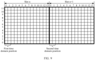
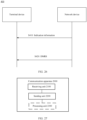
- FIG. 3 is a schematic diagram of a DMRS sending method according to this application.
- the following uses an example in which a transmitting end device is a terminal device and a receiving end device is a network device, to describe in detail steps in the method 300 shown in FIG. 3 .
- S310 The network device sends indication information to the terminal device.
- the terminal device receives the indication information from the network device.
- the indication information indicates a scheduled DMRS port, or the indication information indicates a DMRS port configured by the network device.
- the indication information may be sent by using downlink control information (downlink control information, DCI).
- the scheduled DMRS port belongs to a DMRS port set, and the DMRS port set includes M DMRS ports. That is, the scheduled DMRS port is one or more of the M DMRS ports.
- the M DMRS ports may be DMRS ports that can be supported by a system at most. For example, M is an integer greater than 12.
- the M DMRS ports may correspond to R time domain positions, in other words, the M DMRS ports may be mapped to the R time domain positions, where R is an integer greater than or equal to 2.
- R is an integer greater than or equal to 2.
- the M DMRS ports may be mapped to two time domain positions or three time domain positions. Each time domain position occupies or corresponds to one or more consecutive symbols, and quantities of symbols occupied by any two time domain positions may be equal or unequal.
- the R time domain positions may be located in a same scheduling time unit, or may be located in different scheduling time units.
- each time domain position corresponds to one DMRS port set.
- the R time domain positions correspond to R DMRS port sets. Any two of the R DMRS port sets are different, in other words, the R DMRS port sets are different from each other.
- Each DMRS port set includes a plurality of DMRS ports, for example, includes 6, 12, or 24 DMRS ports, and quantities of DMRS ports included in any two DMRS port sets may be equal or may unequal.
- a DMRS set in this application is only to facilitate descriptions of a relationship between a DMRS port corresponding to one time domain position and DMRS ports corresponding to different time domain positions. During actual implementation, there may be no concept of a set. However, for a feature of the DMRS port corresponding to one time domain position, for example, a quantity of DMRS ports or a DMRS time-frequency position pattern, refer to descriptions of a feature of a corresponding DMRS set in this application.
- S320 The terminal device sends a DMRS on the scheduled DMRS port.
- the network device receives the DMRS from the terminal device on the scheduled DMRS port.
- sending (or receiving) the DMRS may also be referred to as sending (or receiving) a DMRS sequence or sending (or receiving) the DMRS port.
- different DMRS port sets for example, a first DMRS port set and a second DMRS port set
- at least two time domain positions for example, a first time domain position and a second time domain position.
- a DMRS port to which the front-loaded DMRS symbol is mapped in a current protocol may be mapped to the first time domain position
- a DMRS port different from the DMRS port to which the front-loaded DMRS symbol is mapped in the current protocol may be mapped to the second time domain position. That is, DMRS ports (for example, DMRS ports 0 to 11) in the current protocol may be mapped to the first time domain position, and DMRS ports (for example, DMRS ports 12 to 23) newly added in comparison with the current protocol may be mapped to the second time domain position.
- a number on a horizontal axis indicates an index of a symbol in a slot
- a number on a vertical axis indicates an index of a subcarrier in an RB.
- an example in which a slot includes 14 symbols is used for description. During actual implementation, a quantity of symbols included in a slot may not be 14, and may be, for example, 12. This case is also applicable to this application.
- the R time domain positions are located in a same scheduling time unit.
- the R time domain positions correspond to a same scheduling time unit.
- the scheduling time unit is a slot, and the R time domain positions may be located in a same slot.
- Two time domain positions that are closest to each other in time domain and that are in the R time domain positions may be consecutive in time domain, or may be nonconsecutive in time domain.
- this solution is applicable to a common scheduling scenario, namely, a scenario in which a scheduled PUSCH corresponds to a scheduling time unit, for example, a scenario in which the scheduled PUSCH corresponds to a slot.
- a PUSCH corresponds to a scheduling time unit means that a time domain resource corresponding to the PUSCH includes only one or more symbols in the scheduling time unit.
- the two time domain positions corresponding to the M DMRS ports are respectively denoted as: a first time domain position and a second time domain position.
- the first time domain position and the second time domain position may be located in a same scheduling time unit.
- the first time domain position and the second time domain position may be located in a same slot.
- quantities of symbols occupied by the first time domain position and the second time domain position may be equal or unequal.
- the first time domain position and the second time domain position may each occupy two symbols; or the first time domain position occupies one symbol, and the second time domain position occupies two symbols.
- the first time domain position and the second time domain position may be nonconsecutive in time domain.
- first time domain position is located before the second time domain position in time domain, there may be an interval of one or more symbols between the last symbol corresponding to the first time domain position and the first symbol corresponding to the second time domain position. If the first time domain position is located after the second time domain position in time domain, there may be an interval of one or more symbols between the last symbol corresponding to the second time domain position and the first symbol corresponding to the first time domain position.
- the scheduling time unit is a slot is used as an example.
- the first time domain position may occupy symbols 0 and 1 (namely, the first symbol and the second symbol) in a slot
- the second time domain position may occupy symbols 7 and 8 (namely, the eighth symbol and the ninth symbol) in the slot.
- the first time domain position and the second time domain position may be consecutive in time domain.
- the first time domain position and the second time domain position may jointly occupy a plurality of consecutive symbols in a scheduling time unit.
- the scheduling time unit is a slot is used as an example.
- the first time domain position may occupy the first symbol and the second symbol in a slot, and the second time domain position may occupy the third symbol and the fourth symbol in the slot.
- the first symbol to the fourth symbol are consecutive symbols.
- the first time domain position is used to send a front-loaded DMRS.
- the first time domain position may be a front-loaded DMRS symbol.
- the second time domain position is used to send an additional DMRS.
- the second time domain position may be an additional DMRS symbol.
- the first time domain position may be configured in a manner of configuring the front-loaded DMRS symbol, and/or the second time domain position may be configured in a manner of configuring the additional DMRS symbol. Therefore, the first time domain position can be configured without modifying the manner of configuring the front-loaded DMRS symbol in the current protocol, and the second time domain position can be configured without modifying the manner of configuring the additional DMRS symbol in the current protocol.
- the front-loaded DMRS symbol may be configured for each slot, and a position of the front-loaded DMRS symbol corresponds to DMRS ports 0 to 11.
- An existing terminal device may send, on the front-loaded DMRS symbol, a DMRS corresponding to one or more of the DMRS ports 0 to 11.
- the scheduling time unit may be a slot, and the first time domain position and the second time domain position may be configured for each slot.
- the first time domain position may be a front-loaded DMRS symbol, and the second time domain position may be an additional DMRS symbol. If the existing terminal device sends, in the second time domain position, the DMRS sent on the front-loaded DMRS symbol, the existing terminal device may be compatible with the terminal device provided in this application, in other words, the existing terminal device and the terminal device provided in this application may be paired for transmission.
- the three time domain positions corresponding to the M DMRS ports are respectively denoted as: a first time domain position, a second time domain position, and a third time domain position.
- the first time domain position, the second time domain position, and the third time domain position may be located in a same scheduling time unit.
- the first time domain position, the second time domain position, and the third time domain position may correspond to a same scheduling time unit.
- the scheduling time unit is a slot
- the first time domain position, the second time domain position, and the third time domain position may be located in a same slot.
- quantities of symbols occupied by any two of the first time domain position, the second time domain position, and the third time domain position may be equal or unequal.
- the first time domain position, the second time domain position, and the third time domain position may each occupy two symbols.
- the third time domain position occupies three symbols.
- At least two of the first time domain position, the second time domain position, and the third time domain position may be nonconsecutive in time domain.
- the scheduling time unit is a slot is used as an example.
- the first time domain position may occupy symbols 0 and 1 in a slot
- the second time domain position may occupy symbols 2 and 3 in the slot
- the third time domain position may occupy symbols 7 and 8 in the slot.
- the first time domain position and the second time domain position are consecutive in time domain
- the second time domain position and the third time domain position are nonconsecutive in time domain.
- any two of the first time domain position, the second time domain position, and the third time domain position are nonconsecutive in time domain.
- the scheduling time unit is a slot is used as an example. Refer to FIG. 7 .
- the first time domain position may occupy symbols 0 and 1 in a slot
- the second time domain position may occupy symbols 3 and 4 in the slot
- the third time domain position may occupy symbols 7 and 8 in the slot.
- the first time domain position, the second time domain position, and the third time domain position may be consecutive in time domain.
- the scheduling time unit is a slot is used as an example.
- the first time domain position may occupy symbols 0 and 1 in a slot
- the second time domain position may occupy symbols 2 and 3 in the slot
- the third time domain position may occupy symbols 4 and 5 in the slot.
- the R time domain positions are located in different scheduling time units.
- the R time domain positions correspond to R scheduling time units.
- the scheduling time unit is a slot
- the R time domain positions correspond to R slots.
- DMRSs of different DMRS ports may be carried in different scheduling time units.
- DMRS overheads can be reduced.
- a scheduled PUSCH corresponds to a plurality of scheduling time units
- a scenario in which the scheduled PUSCH corresponds to a plurality of slots means that a time domain resource corresponding to the scheduled PUSCH includes one or more symbols in each of the plurality of scheduling time units.
- the first time domain position and the second time domain position may be located in different scheduling time units.
- the first time domain position and the second time domain position may be located in different slots.
- quantities of symbols occupied by the first time domain position and the second time domain position may be equal or unequal.
- the first time domain position and the second time domain position may each occupy two symbols; or the first time domain position occupies one symbol, and the second time domain position occupies two symbols.
- first time domain position and the second time domain position may correspond to symbols with a same index in different scheduling time units, or the first time domain position and the second time domain position may correspond to symbols with different indexes in different scheduling time units.
- the scheduling time unit corresponding to the first time domain position and the scheduling time unit corresponding to the second time domain position may be consecutive in time domain.
- the scheduling time unit corresponding to the first time domain position and the scheduling time unit corresponding to the second time domain position are two adjacent scheduling time units.
- the scheduling time unit is a slot is used as an example.
- the first time domain position may correspond to symbols 0 and 1 in a slot n
- the second time domain position may correspond to symbols 0 and 1 in a slot n+1.
- the scheduling time unit corresponding to the first time domain position and the scheduling time unit corresponding to the second time domain position may be nonconsecutive in time domain.
- the scheduling time unit corresponding to the first time domain position and the scheduling time unit corresponding to the second time domain position are two scheduling time units that are not adjacent. In other words, there is an interval of one or more scheduling time units between the scheduling time unit corresponding to the first time domain position and the scheduling time unit corresponding to the second time domain position.
- the scheduling time unit is a slot is used as an example.
- the first time domain position may correspond to symbols 0 and 1 in a slot n
- the second time domain position may correspond to symbols 0 and 1 in a slot n+2.
- the first time domain position is used to send a front-loaded DMRS.
- the first time domain position may be a front-loaded DMRS symbol.
- the second time domain position is used to send the front-loaded DMRS.
- the second time domain position may be a front-loaded DMRS symbol.
- the first time domain position, the second time domain position, and the third time domain position may be located in different scheduling time units.
- any two of the first time domain position, the second time domain position, and the third time domain position may correspond to different scheduling time units.
- the scheduling unit is a slot, and a slot corresponding to the first time domain position, a slot corresponding to the second time domain position, and a slot corresponding to the third time domain position are different from each other.
- DMRSs of different DMRS ports may be carried in different scheduling time units.
- DMRS overheads can be reduced.
- quantities of symbols occupied by any two of the first time domain position, the second time domain position, and the third time domain position may be equal or unequal.
- the first time domain position, the second time domain position, and the third time domain position may each occupy two symbols.
- the third time domain position occupies three symbols.
- first time domain position, the second time domain position, and the third time domain position may correspond to symbols with a same index in different scheduling time units, or the first time domain position, the second time domain position, and the third time domain position may correspond to symbols with different indexes in different scheduling time units.
- the scheduling time unit corresponding to the first time domain position, the scheduling time unit corresponding to the second time domain position, and the scheduling time unit corresponding to the third time domain position may be consecutive in time domain.
- the scheduling time unit corresponding to the first time domain position, the scheduling time unit corresponding to the second time domain position, and the scheduling time unit corresponding to the third time domain position are three adjacent scheduling time units.
- the scheduling time unit is a slot is used as an example.
- the first time domain position may correspond to symbols 0 and 1 in a slot n
- the second time domain position may occupy symbols 0 and 1 in a slot n+1
- the third time domain position may correspond to symbols 0 and 1 in a slot n+2.
- At least two of the scheduling time unit corresponding to the first time domain position, the scheduling time unit corresponding to the second time domain position, and the scheduling time unit corresponding to the third time domain position may be nonconsecutive in time domain.
- At least two of the scheduling time unit corresponding to the first time domain position, the scheduling time unit corresponding to the second time domain position, and the scheduling time unit corresponding to the third time domain position are not adjacent scheduling time units.
- the scheduling time unit is a slot is used as an example.
- the first time domain position may correspond to symbols 0 and 1 in a slot n
- the second time domain position may correspond to symbols 0 and 1 in a slot n+1
- the third time domain position may correspond to symbols 0 and 1 in a slot n+3. It should be understood that the first time domain position, the second time domain position, and the third time domain position are not configured in a slot n+2 that is not shown in FIG. 12 . That is, no DMRS port is mapped to the slot n+2.
- the scheduling time unit is a slot
- the first time domain position may correspond to symbols 0 and 1 in a slot n
- the second time domain position may correspond to symbols 0 and 1 in a slot n+2
- the third time domain position may correspond to symbols 0 and 1 in a slot n+4.
- the first time domain position is used to send a front-loaded DMRS.
- the first time domain position may be a front-loaded DMRS symbol.
- the second time domain position is used to send the front-loaded DMRS.
- the second time domain position may be a front-loaded DMRS symbol.
- the third time domain position is used to send the front-loaded DMRS.
- the first time domain position may be a front-loaded DMRS symbol.
- a DMRS port set corresponding to the first time domain position and a DMRS port set corresponding to the second time domain position are respectively denoted as: a first DMRS port set and a second DMRS port set.
- a quantity of DMRS ports included in the first DMRS port set and a quantity of DMRS ports included in the second DMRS port set may be equal or unequal.
- the first DMRS port set may include 12 DMRS ports
- the second DMRS port set may include 6, 12, or 24 DMRS ports.
- the first DMRS port set may include 24 DMRS ports
- the second DMRS port set may include 6, 12, or 24 DMRS ports.
- the first DMRS port set may include six DMRS ports
- the second DMRS port set may include 12 or 24 DMRS ports.
- the DMRS ports included in the first DMRS port set and the second DMRS port set are partially the same and partially different.
- the DMRS ports included in the first DMRS port set and the second DMRS port set are not exactly the same and have an intersection set.
- the second DMRS port set includes some or all of the DMRS ports in the first DMRS port set and a DMRS port that is in the M DMRS ports and that does not belong to the first DMRS port set.
- the first DMRS port set includes some or all of the DMRS ports in the second DMRS port set and a DMRS port that is in the M DMRS ports and that does not belong to the second DMRS port set.
- the first DMRS port set may include DMRS ports 0 to 11 (in other words, the first DMRS port set includes only the DMRS ports 0 to 11), and the second DMRS port set may include DMRS ports 0 to 23 (in other words, the second DMRS port set includes only the DMRS ports 0 to 23).
- the first DMRS port set may include DMRS ports 0 to 23, and the second DMRS port set may include DMRS ports 0 to 11.
- the first DMRS port set may include DMRS ports 0 to 11, and the second DMRS port set may include DMRS ports 0 to 5 and DMRS ports 12 to 23.
- the first DMRS port set may include DMRS ports 0 to 5 and DMRS ports 12 to 23, and the second DMRS port set may include DMRS ports 0 to 11.
- the first DMRS port set may include DMRS ports 0 to 11
- the second DMRS port set may include DMRS ports 0 to 11 and DMRS ports 24 to 35.
- the second DMRS port set may include DMRS ports 0 to 11 and DMRS ports 24 to 35
- the second DMRS port may include DMRS ports 0 to 11.
- the first DMRS port set may include DMRS ports 0 to 23, and the second DMRS port set may include DMRS ports 0 to 11 and DMRS ports 24 to 35.
- the second DMRS port set may include DMRS ports 0 to 11 and DMRS ports 24 to 35, and the second DMRS port may include DMRS ports 0 to 23.
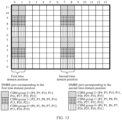
- FIG. 13 to FIG. 15 show several examples in which a first DMRS port set and a second DMRS port set are different and have an intersection set.
- the first DMRS port set includes DMRS ports 0 to 23
- the second DMRS port set includes DMRS ports 0 to 11 and DMRS ports 24 to 35.
- the 36 DMRS ports correspond to three CDM groups, and each CDM group supports 12 DMRS ports.
- each of three CDM groups corresponding to a first time domain position corresponds to eight REs
- the eight REs correspond to eight DMRS ports.
- Each of three CDM groups corresponding to a second time domain position corresponds to eight REs, and the eight REs correspond to eight DMRS ports.
- the first time domain position and the second time domain position are located in a same slot, and the first time domain position and the second time domain position are nonconsecutive in time domain.
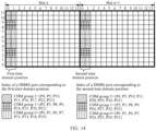
- the first time domain position and the second time domain position are located in different slots, and a slot occupied by the first time domain position and a slot occupied by the second time domain position are consecutive in time domain.
- the first time domain position and the second time domain position are located in different slots, and a slot occupied by the first time domain position and a slot occupied by the second time domain position are nonconsecutive in time domain. It should be understood that no DMRS port is mapped to a slot n+1 that is not shown in FIG. 15 .
- DMRS ports 0 to 11 are DMRS ports in an existing protocol
- DMRS ports 12 to 47 are newly introduced DMRS ports.
- the newly introduced DMRS ports may be represented by using new indexes, for example, may be represented by using indexes 12 to 47. However, this is not limited in this application.
- the newly introduced DMRS ports may alternatively be represented by using indexes 24 to 59.
- the DMRS ports included in the first DMRS port set and the second DMRS port set are completely different. In other words, the DMRS ports included in the first DMRS port set and the second DMRS port set have no intersection set.
- the first DMRS port set may include DMRS ports 0 to 11, and the second DMRS port set may include DMRS ports 12 to 23.
- the first DMRS port set may include DMRS ports 12 to 23, and the second DMRS port set may include DMRS ports 0 to 11.
- the first DMRS port set may include DMRS ports 0 to 11, and the second DMRS port set may include DMRS ports 12 to 35.
- the first DMRS port set may include DMRS ports 12 to 35, and the second DMRS port set may include DMRS ports 0 to 11.
- the first DMRS port set may include DMRS ports 0 to 23, and the second DMRS port set may include DMRS ports 24 to 35.
- the first DMRS port set may include DMRS ports 24 to 35, and the second DMRS port set may include DMRS ports 0 to 23.
- the first DMRS port set may include DMRS ports 0 to 23, and the second DMRS port set may include DMRS ports 24 to 47.
- the first DMRS port set may include DMRS ports 24 to 47, and the second DMRS port set may include DMRS ports 0 to 23.
- the first DMRS port set may include a DMRS port whose index is an odd number
- the second DMRS port set may include a DMRS port whose index is an even number
- the first DMRS port set may include a DMRS port whose index is an even number
- the second DMRS port set may include a DMRS port whose index is an odd number.
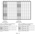
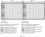
- FIG. 16 to FIG. 23 show several examples in which a first DMRS port set and a second DMRS port set have no intersection set.
- the first DMRS port set includes DMRS ports 0 to 23
- the second DMRS port set includes DMRS ports 24 to 35.
- the first DMRS port set includes DMRS ports 0 to 23
- the second DMRS port set includes DMRS ports 24 to 47.
- the 36 DMRS ports correspond to three CDM groups, and each CDM group supports 12 DMRS ports.
- each of three CDM groups corresponding to a first time domain position corresponds to eight REs
- the eight REs correspond to eight DMRS ports.
- Each of three CDM groups corresponding to a second time domain position corresponds to eight REs, four of the eight REs are consecutive, the other four REs are nonconsecutive, and the four consecutive REs correspond to four ports.
- a CDM group 0 corresponding to the second time domain position in FIG. 16 is used as an example.
- DMRSs corresponding to the DMRS ports corresponding to the four REs whose frequency domain positions are subcarriers 6 and 7 and whose time domain positions are symbols 7 and 8 are actually repetitions of DMRSs corresponding to the DMRS ports corresponding to the four REs whose frequency domain positions are subcarriers 0 and 1 and whose time domain positions are symbols 7 and 8.
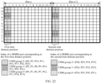
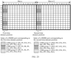
- the 48 DMRS ports correspond to three CDM groups, and each CDM group supports 16 DMRS ports.
- each CDM group corresponding to a first time domain position corresponds to eight REs
- the eight REs correspond to eight DMRS ports.
- Each CDM group corresponding to a second time domain position corresponds to eight REs
- the eight REs correspond to eight DMRS ports.
- the first time domain position and the second time domain position are located in a same slot, and the first time domain position and the second time domain position are nonconsecutive in time domain.
- the first time domain position and the second time domain position are located in a same slot, and the first time domain position and the second time domain position are consecutive in time domain.
- the first time domain position and the second time domain position are located in different slots, and a slot corresponding to the first time domain position and a slot corresponding to the second time domain position are consecutive in time domain.
- the first time domain position and the second time domain position are located in different slots, and a slot corresponding to the first time domain position and a slot corresponding to the second time domain position are nonconsecutive in time domain. It should be understood that no DMRS port is mapped to a slot n+1 that is not shown in FIG. 22 and FIG. 23 .
- a predefined rule is satisfied between a configuration of the first DMRS port set and/or a configuration of the second DMRS port set and the scheduling time unit, which may also be understood as that the predefined rule is satisfied between a configuration of the first time domain position and/or a configuration of the second time domain position and the scheduling time unit.
- it may be determined, according to the predefined rule, whether the first time domain position is configured in the scheduling unit or the first DMRS port set can be mapped to the scheduling unit, and/or whether the second time domain position is configured in the scheduling unit or the second DMRS port set can be mapped to the scheduling unit.
- configuring a first DMRS set may alternatively be understood as configuring the first time domain position
- configuring a second DMRS set may alternatively be understood as configuring the second time domain position
- N may be configured or predefined by a system.
- N may be a quantity of the plurality of scheduling time units corresponding to the scheduled PUSCH.
- N 4.
- the first DMRS port set may be configured in the first scheduling time unit
- the second DMRS port set may be configured in the second scheduling time unit
- no DMRS port may be configured in the third scheduling time unit or the fourth scheduling time unit.
- N may be a quantity of scheduling time units included in a radio frame whose length is 1 0 ms.
- N may be a quantity of slots included in the radio frame whose length is 10 ms.
- a value of N may be configured by using radio resource control (radio resource control, RRC) signaling or downlink control information (downlink control information, DCI).
- RRC radio resource control
- DCI downlink control information
- a value set may be configured by using RRC signaling, and a specific value of N in the value set is indicated by DCI.
- different values of N are indicated by different status values of a field.
- N the quantity of scheduling time units corresponding to the scheduled PUSCH is greater than N
- a larger value of N indicates sparser DMRS sending.
- DMRS overheads are reduced while channel estimation performance is almost not affected.
- only the first DMRS port set may be configured in a scheduling time unit whose index is an even number, and/or only the second DMRS port set may be configured in a scheduling time unit whose index is an odd number.
- m indicates the index of the scheduling time unit
- m 0, 1, 2, ..., that is, a value of m may start from 0, but this is not limited in this application.
- m 1, 2, 3, ..., that is, a value of m may alternatively start from 1.
- only the first DMRS port set may be configured in an odd-numbered scheduling time unit, and/or only the second DMRS port set may be configured in an even-numbered scheduling time unit.
- the predefined rule may be: There is an interval of P scheduling time units between a scheduling time unit in which only the first DMRS port set is configured and a scheduling time unit in which only the second DMRS port set is configured, where P is a positive integer.
- only the first DMRS port set or only the second DMRS port set may be configured in a scheduling time unit 0, namely, a scheduling time unit whose index is 0; or only the first DMRS port set or only the second DMRS port set may be configured in the first scheduling time unit in a plurality of scheduling time units corresponding to a scheduled PUSCH.
- the predefined rule may be:
- N may be configured or predefined by a system.
- N is a quantity of the plurality of scheduling time units corresponding to the scheduled PUSCH.
- the first DMRS port set and the second DMRS port set may be configured in the first scheduling time unit, and no DMRS port may be configured in the second scheduling time unit, the third scheduling time unit, or the fourth scheduling time unit.
- N may be a quantity of scheduling time units (for example, slots) included in a radio frame whose length is 10 ms.
- a value of N may be configured by using RRC signaling or DCI.
- a value set may be configured by using RRC signaling, and a specific value of N in the value set is indicated by DCI.
- different values of N are indicated by different status values of a field.
- N the quantity of scheduling time units corresponding to the scheduled PUSCH is greater than N
- a larger value of N indicates sparser DMRS sending.
- DMRS overheads are reduced while channel estimation performance is almost not affected.
- the predefined rule may be:
- the first DMRS port set and the second DMRS port set are configured in a scheduling time unit whose index is an even number, and the first DMRS port set and the second DMRS port set are not configured in a scheduling time unit whose index is an odd number.
- the predefined rule may be:
- the first DMRS port set and the second DMRS port set are configured in a scheduling time unit whose index is an odd number, and the first DMRS port set and the second DMRS port set are not configured in a scheduling time unit whose index is an even number.
- the predefined rule may be:
- the first DMRS port set and the second DMRS port set are configured in an even-numbered scheduling time unit, and the first DMRS port set and the second DMRS port set are not configured in an odd-numbered scheduling time unit.
- the predefined rule may be:
- the first DMRS port set and the second DMRS port set are configured in an odd-numbered scheduling time unit, and the first DMRS port set and the second DMRS port set are not configured in an even-numbered scheduling time unit.
- the predefined rule may be:
- the first DMRS port set and the second DMRS port set are configured at an interval of P scheduling time units, where P is a positive integer.
- the first DMRS port set and the second DMRS port set may be configured in scheduling time units 0, 3, 6, 9, ..., and the first DMRS port set and the second DMRS port set may not be configured in another scheduling time unit.
- the predefined rule may be: In a plurality of scheduling time units corresponding to a scheduled PUSCH, the first DMRS port set and the second DMRS port set are configured at an interval of P scheduling time units, where P is a positive integer.
- the first DMRS port set and the second DMRS port set may be configured in the first scheduling time unit and the fourth scheduling time unit, and the first DMRS port set and the second DMRS port set may not be configured in another scheduling time unit.
- a DMRS port set corresponding to the first time domain position, a DMRS port set corresponding to the second time domain position, and a DMRS port set corresponding to the third time domain position are respectively denoted as: a first DMRS port set, a second DMRS port set, and a third DMRS port set.
- quantities of DMRS ports included in any two of the three DMRS port sets may be equal or unequal.
- the first DMRS port set may include 6, 12, or 24 DMRS ports
- the second DMRS port set may include 6, 12, or 24 DMRS ports
- the third DMRS port set may include 6, 12, or 24 DMRS ports.
- the DMRS ports included in at least two of the first DMRS port set, the second DMRS port set, and the third DMRS port set are partially the same and partially different.
- the first DMRS port set may include DMRS ports 0 to 11
- the second DMRS port set may include 0 to 23
- the third DMRS port set may include DMRS ports 24 to 35.
- the first DMRS port set may include DMRS ports 0 to 11
- the second DMRS port set may include 0 to 23
- the third DMRS port set may include DMRS ports 0 to 5 and 24 to 35.
- the DMRS ports included in any two of the first DMRS port set, the second DMRS port set, and the third DMRS port set are completely different.
- the first DMRS port set may include DMRS ports 0 to 11, the second DMRS port set may include 12 to 23, and the third DMRS port set may include DMRS ports 24 to 35.
- the first DMRS port set may include DMRS ports 0 to 11, the second DMRS port set may include 12 to 23, and the third DMRS port set may include DMRS ports 24 to 47.
- FIG. 24 and FIG. 25 show several examples in which DMRS ports included in any two of a first DMRS port set, a second DMRS port set, and a third DMRS port set are completely different.
- the first DMRS port set includes DMRS ports 0 to 11
- the second DMRS port set includes DMRS ports 12 to 23
- the third DMRS port set includes DMRS ports 23 to 35.
- each support a maximum of 36 DMRS ports, that is, M 36.
- the 36 DMRS ports correspond to three CDM groups, and each CDM group supports 12 DMRS ports.
- each of three CDM groups corresponding to a first time domain position corresponds to eight REs, four of the eight REs are consecutive, the other four REs are nonconsecutive, and the four consecutive REs correspond to four ports.
- Each of three CDM groups corresponding to a second time domain position corresponds to eight REs, four of the eight REs are consecutive, the other four REs are nonconsecutive, and the four consecutive REs correspond to four ports.
- Each of three CDM groups corresponding to a third time domain position corresponds to eight REs, four of the eight REs are consecutive, the other four REs are nonconsecutive, and the four consecutive REs correspond to four ports.
- a CDM group 0 corresponding to the first time domain position in FIG. 24 is used as an example.
- Four REs whose frequency domain positions are subcarriers 0 and 1 and whose time domain positions are symbols 0 and 1 correspond to DMRS ports 0, 1, 6, and 7.
- Four REs whose frequency domain positions are subcarriers 6 and 7 and whose time domain positions are symbols 0 and 1 also correspond to the DMRS ports 0, 1, 6, and 7.
- DMRSs corresponding to the DMRS ports corresponding to the four REs whose frequency domain positions are subcarriers 6 and 7 and whose time domain positions are symbols 0 and 1 are actually repetitions of DMRSs corresponding to the DMRS ports corresponding to the four REs whose frequency domain positions are subcarriers 0 and 1 and whose time domain positions are symbols 0 and 1.
- the first time domain position, the second time domain position, and the third time domain position are located in a same slot, and the three time domain positions are consecutive in time domain.
- the first time domain position, the second time domain position, and the third time domain position are located in different slots, and slots corresponding to the three time domain positions are consecutive in time domain.
- a predefined rule is satisfied between a configuration of the first DMRS port set, a configuration of the second DMRS port set, and/or a configuration of the third DMRS port set and the scheduling time unit, which may also be understood as that the predefined rule is satisfied between a configuration of the first time domain position, a configuration of the second time domain position, and/or a configuration of the third time domain position and the scheduling time unit.
- N may be configured or predefined by a system.
- R may be configured or predefined by a system.
- the predefined rule may be: There is an interval of P scheduling time units between a scheduling time unit in which only the first DMRS port set is configured and a scheduling time unit in which only the second DMRS port set is configured, and there is an interval of Q scheduling time units between the scheduling time unit in which only the second DMRS port set is configured and a scheduling time unit in which only the third DMRS port set is configured, where both P and Q are positive integers, and P and Q may be equal or unequal.
- only the first DMRS port set may be configured in a scheduling time unit 0, namely, a scheduling time unit whose index is 0; or only the first DMRS port set may be configured in the first scheduling time unit in a plurality of scheduling time units corresponding to a scheduled PUSCH.
- only the first DMRS port set may be configured in a scheduling time unit n+2*k*(P+1)
- only the second DMRS port set may be configured in a scheduling time unit n+(2*k+1)*(P+1)
- only the third DMRS port set may be configured in a scheduling time unit n+(2*k+2)*(P+1)
- k 0, 1, 2, 3, 4, ..., n is an integer greater than or equal to 0, and n+2*k*(P+1) and n+(2*k+2)*(P+1) each are an index of the scheduling time unit.
- the predefined rule may be:
- N may be configured or predefined by a system.
- R may be configured or predefined by a system.
- the predefined rule may be:
- the first DMRS port set, the second DMRS port set, and the third DMRS port set are configured in a scheduling time unit whose index is an even number, and the first DMRS port set, the second DMRS port set, and the third DMRS port set are not configured in a scheduling time unit whose index is an odd number.
- the predefined rule may be:
- the first DMRS port set, the second DMRS port set, and the third DMRS port set are configured in a scheduling time unit whose index is an odd number, and the first DMRS port set, the second DMRS port set, and the third DMRS port set are not configured in a scheduling time unit whose index is an even number.
- the predefined rule may be:
- the first DMRS port set, the second DMRS port set, and the third DMRS port set are configured in an even-numbered scheduling time unit, and the first DMRS port set, the second DMRS port set, and the third DMRS port set are not configured in an odd-numbered scheduling time unit.
- the predefined rule may be:
- the first DMRS port set, the second DMRS port set, and the third DMRS port set are configured in an odd-numbered scheduling time unit, and the first DMRS port set, the second DMRS port set, and the third DMRS port set are not configured in an even-numbered scheduling time unit.
- the predefined rule may be: The first DMRS port set, the second DMRS port set, and the third DMRS port set are configured at an interval of P scheduling time units, where P is a positive integer.
- the first DMRS port set, the second DMRS port set, and the third DMRS port set may be configured in scheduling time units 0, 3, 6, 9, ..., and the first DMRS port set and the second DMRS port set may not be configured in another scheduling time unit.
- the predefined rule may be: In a plurality of scheduling time units corresponding to a scheduled PUSCH, the first DMRS port set, the second DMRS port set, and the third DMRS port set are configured at an interval of P scheduling time units, where P is a positive integer.
- the first DMRS port set, the second DMRS port set, and the third DMRS port set may be configured in the first scheduling time unit and the fourth scheduling time unit, and the first DMRS port set, the second DMRS port set, and the third DMRS port set are not configured in another scheduling time unit.
- predefined rule in this application may alternatively be any other reasonable rule, and a specific rule of the predefined rule is not limited in this application.
- the first time domain position, the second time domain position, and the third time domain position in the DMRS patterns shown in FIG. 13 to FIG. 25 are merely examples.
- a symbol or symbols specifically occupied by the first time domain position, the second time domain position, and the third time domain position are not limited in this application.
- the first time domain position corresponds to symbols 0 and 1.
- the first time domain position may correspond to symbols 1 and 2.
- a correspondence between a CDM group and a DMRS port in each of the DMRS patterns shown in FIG. 13 to FIG. 25 is merely an example.
- a CDM group and a DMRS port may not be shown in the figure, or a quantity of CDM groups may not be 3.
- a maximum of three CDM groups are supported.
- the first time domain position may correspond to three CDM groups
- the second time domain position may correspond to three other CDM groups, for example, CDM groups 3 to 5.
- a CDM group 0 may correspond to a DMRS port corresponding to a CDM group 2 in FIG. 13
- the CDM group 2 may correspond to a DMRS port corresponding to the CDM group 0 in FIG. 13 .
- DMRS pattern is not limited in this application.
- the DMRS patterns shown in FIG. 13 to FIG. 25 are merely examples, and should not constitute any limitation on this application.
- different DMRS port sets are respectively mapped to at least two time domain positions, to support more than 12 orthogonal DMRS ports, for example, 24, 36, 48, or even more orthogonal DMRS ports.
- more spatial layers can be used for parallel transmission and a system capacity can be improved.
- the first time domain position and the second time domain position may be configured for each slot, the first time domain position may be used to send a front-loaded DMRS, and the second time domain position may be used to send an additional DMRS.
- the terminal device provided in this application may be compatible with a legacy terminal device in some scenarios, and cannot be compatible with the legacy terminal device in some other scenarios. The following provides descriptions.
- the legacy terminal device refers to a terminal device (namely, an existing terminal device, for example, a terminal device in a 4G system or a terminal device in a current 5G system) supported by a current standard or a previous standard. Therefore, the legacy terminal device can identify DMRS ports 0 to 11 only on a front-loaded DMRS symbol and an additional DMRS symbol. That the legacy terminal device is compatible means that during multi-user pairing, the legacy terminal device and a new terminal device may be scheduled on a same time-frequency resource for transmission.
- the legacy terminal device is compatible.
- An additional DMRS of the legacy terminal device is a repetition of a front-loaded DMRS.
- the legacy terminal device sends, on the additional DMRS symbol, a DMRS that is the same as that on the front-loaded DMRS symbol.
- the existing terminal device when an orthogonal DMRS port is added, the existing terminal device can be further compatible.
- the terminal device provided in this application and a terminal device that supports only an existing standard capability can perform multi-user pairing, and no hardware or software update needs to be performed on the existing terminal device.
- the legacy terminal device is not compatible.
- the legacy terminal device does not send a DMRS on the additional DMRS symbol.
- the terminal device provided in this application and a terminal device that supports only an existing standard capability cannot perform multi-user pairing.
- the terminal device may determine a CDM group and OCC that correspond to a DMRS port, and may generate a corresponding DMRS sequence.
- a correspondence between a DMRS port, a CDM group, and OCC is shown in a part or all of Table 2.
- p ⁇ indicates an index of the DMRS port
- ⁇ indicates an index of the CDM group
- ⁇ indicates a subcarrier offset
- w f ( k' + 2t) indicates frequency domain OCC
- w t ( l ') indicates the frequency domain OCC.
- DMRSextendFlag DMRS extension identifier
- sequence r ( n ) may be mapped to each RE according to the foregoing formula (4).
- the network device may indicate the scheduled DMRS port to the terminal device by using the indication information.
- the indication information may be an index value, the index value corresponds to one or more DMRS ports, and the one or more DMRS ports are scheduled DMRS ports.
- a correspondence between an index value (the indication information) and a DMRS port may be shown in a part or all of one or more of Table 3 to Table 6.
- a rank (rank) When a rank (rank) is 1, the correspondence between an index value (the indication information) and a DMRS port is shown in Table 3. It should be understood that for uplink transmission, when a rank (rank) configured by the network device for uplink transmission of the terminal device is 1, the terminal device requires only one DMRS port when sending uplink data, in other words, a quantity of DMRS ports scheduled by the network device is 1.
- N/A in this specification indicates that a corresponding quantity of symbols is 0.
- the index values 0 to 27 are the same as those in Table 7.3.1.1.2-20 in TS 38.212 in the conventional technology.
- the index values 28 to 51 are provided in this embodiment of this application. For example, when the indication information sent by the network device is 30, it indicates that the scheduled DMRS port is a DMRS port whose index is 14, and a quantity of symbols occupied by a CDM group in which the DMRS port is located is 2.
- the last column in Table 3 may alternatively not be included.
- two additional DMRS symbols are configured by default.
- a rank (rank) When a rank (rank) is 2, the correspondence between an index value and a DMRS port is shown in Table 4. It should be understood that for uplink transmission, when a rank (rank) configured by the network device for uplink transmission of the terminal device is 2, the terminal device requires two DMRS ports when sending uplink data, in other words, a quantity of DMRS ports scheduled by the network device is 2.
- the index values 0 to 18 are the same as those in Table 7.3.1.1.2-21 in TS 38.212 in the conventional technology.
- the index values 19 to 30 are provided in this embodiment of this application. For example, when the indication information sent by the network device is 24, it indicates that the scheduled DMRS ports are DMRS ports whose indexes are 22 and 23.
- the last column in Table 4 may alternatively not be included.
- two additional DMRS symbols are configured by default.
- a rank (rank) When a rank (rank) is 3, the correspondence between an index value and a DMRS port is shown in Table 5. It should be understood that for uplink transmission, when a rank (rank) configured by the network device for uplink transmission of the terminal device is 3, the terminal device requires three DMRS ports when sending uplink data, in other words, a quantity of DMRS ports scheduled by the network device is 3.
- the index values 0 to 5 are the same as those in Table 7.3.1.1.2-22 in TS 38.212 in the conventional technology.
- the index values 6 to 31 are provided in this embodiment of this application. For example, when the indication information sent by the network device is 9, it indicates that the scheduled DMRS ports are DMRS ports whose indexes are 19, 22, and 23.
- the last column in Table 5 may alternatively not be included.
- two additional DMRS symbols are configured by default.
- a rank (rank) When a rank (rank) is 4, the correspondence between an index value and a DMRS port is shown in Table 6. It should be understood that for uplink transmission, when a rank (rank) configured by the network device for uplink transmission of the terminal device is 4, the terminal device requires four DMRS ports when sending uplink data, in other words, a quantity of DMRS ports scheduled by the network device is 4.
- the index values 0 to 4 are the same as those in Table 7.3.1.1.2-23 in TS 38.212 in the conventional technology.
- the index values 5 to 10 are provided in this embodiment of this application. For example, when the indication information sent by the network device is 7, it indicates that the scheduled DMRS ports are DMRS ports whose indexes are 16, 17, 22, and 23.
- the last column in Table 6 may alternatively not be included.
- two additional DMRS symbols are configured by default.
- a correspondence between an index value (the indication information) and a DMRS port may be shown in a part or all of one or more of Table 7 to Table 10.
- Table 7 Index value (value) Quantity of DMRS CDM groups without data Index of the DMRS port Quantity of front-loaded DMRS symbols 0 1 0 1 1 1 1 1 2 2 0 1 3 2 1 1 4 2 2 1 5 2 3 1 6 3 0 1 7 3 1 1 8 3 2 1 9 3 3 1 10 3 4 1 11 3 5 1 12 3 0 2 13 3 1 2 14 3 2 2 15 3 3 2 16 3 4 2 17 3 5 2 18 3 6 2 19 3 7 2 20 3 8 2 21 3 9 2 22 3 10 2 23 3 11 2 24 1 0 2 25 1 1 2 26 1 6 2 27 1 7 2 28 3 12 2 29 3 13 2 30 3 14 2 31 3 15 2 32 3 16 2 33 3 17 2 34 3 18 2 35 3 19 2 36 3 20 2 37 3 21 2 38 3 22 2 39 3 23 2 40 3 24 2 41 3 25 2 42 3 26 2 43 3 27 2 44 3 28 2 45 3
- Table 8 Index value (value) Quantity of DMRS CDM groups without data Index of the DMRS port Quantity of front-loaded DMRS symbols 0 1 0 and 1 1 1 2 0 and 1 1 2 2 2 and 3 1 3 3 0 and 1 1 4 3 2 and 3 1 5 3 4 and 5 1 6 2 0 and 2 1 7 3 0 and 1 2 8 3 2 and 3 2 9 3 4 and 5 2 10 3 6 and 7 2 11 3 8 and 9 2 12 3 10 and 11 2 13 1 0 and 1 2 14 1 6 and 7 2 15 2 0 and 1 2 16 2 2 and 3 2 17 2 6 and 7 2 18 2 8 and 9 2 19 3 12 and 13 2 20 3 14 and 15 2 21 3 16 and 17 2 22 3 18 and 29 2 23 3 20 and 21 2 24 3 22 and 23 2 25 3 24 and 25 2 26 3 26 and 27 2 27 3 28 and 29 2 28 3 30 and 31 2 29 3 32 and 33 2 30 3 34 and 35
- Table 9 Index value (value) Quantity of DMRS CDM groups without data Index of the DMRS port Quantity of front-loaded DMRS symbols 0 2 0 to 2 1 1 3 0 to 2 1 2 3 3 to 5 1 3 3 0, 1, and 6 2 4 3 2, 3, and 8 2 5 3 4, 5, and 10 2 6 3 12, 13, and 18 2 7 3 14, 15, and 20 2 8 3 16, 17, and 22 2 9 3 19, 21, and 23 2 10 3 24, 25, and 30 2 11 3 26, 27, and 32 2 12 3 28, 29, and 34 2 13 3 31, 33, and 35 2 14 to 31 Reserved Reserved Reserved Reserved
- Table 10 Index value (value) Quantity of DMRS CDM groups without data Index of the DMRS port Quantity of front-loaded DMRS symbols 0 2 0 to 3 1 1 3 0 to 3 1 2 3 0, 1, 6, and 7 2 3 3 2, 3, 8, and 9 2 4 3 4, 5, 10, and 11 2 5 3 12, 13, 18, and 19 2 6 3 14, 15, 20, and 21 2 7 3 16, 17, 22, and 23 2 8 3 24, 25, 30, and 31 2 9 3 26, 27, 32, and 33 2 10 3 28, 29, 34, and 35 2 11 to 31 Reserved Reserved Reserved
- the foregoing mainly describes a solution for sending a DMRS in uplink communication, and the following briefly describes a solution for sending a DMRS in downlink communication.
- FIG. 26 is a schematic diagram of a DMRS sending method according to this application. The following briefly describes steps in the method 400.
- a network device sends indication information to a terminal device.
- the terminal device receives the indication information from the network device.
- the indication information indicates a scheduled DMRS port, or the indication information indicates a DMRS port configured by the network device.
- the indication information may be sent by using DCI.
- the scheduled DMRS port belongs to a DMRS port set, and the DMRS port set includes M DMRS ports.
- the M DMRS ports may be DMRS ports that can be supported by a system at most.
- the M DMRS ports may correspond to R time domain positions, in other words, the M DMRS ports may be mapped to the R time domain positions, where R is an integer greater than or equal to 2.
- the M DMRS ports may be mapped to two time domain positions or three time domain positions. Each time domain position occupies or corresponds to one or more consecutive symbols, and quantities of symbols occupied by any two time domain positions may be equal or unequal.
- Two adjacent time domain positions in the R time domain positions may be consecutive in time domain, or may be nonconsecutive in time domain. That the two time domain positions are adjacent herein means that there is no other time domain position, in the R time domain positions, between the two time domain positions.
- each time domain position corresponds to one DMRS port set, in other words, R time domain positions correspond to R DMRS port sets, and any two of the R port sets are different.
- the uplink-related content in the method 300 is correspondingly changed to downlink-related content.
- the PUSCH in the method 300 is changed to a PDSCH.
- S420 The network device sends a DMRS on the scheduled DMRS port.
- the terminal device receives the DMRS from the network device on the scheduled DMRS port.
- different DMRS port sets (for example, a first DMRS port set and a second DMRS port set) are respectively mapped to at least two time domain positions (for example, a first time domain position and a second time domain position), so that more DMRS ports can be supported, thereby improving a system capacity.
- FIG. 27 is a schematic diagram of a communication apparatus according to an embodiment of this application.
- the communication apparatus 2000 may include a receiving unit 2100 and a sending unit 2200.
- the communication apparatus may further include a processing unit 2200.
- the receiving unit 2100 may be a receiver, an input interface, a pin, a circuit, or the like.
- the receiving unit 2100 may be configured to perform the receiving step in the foregoing method embodiment.
- the sending unit 2200 may be a transmitter, an output interface, a pin, a circuit, or the like.
- the sending unit 2200 may be configured to perform the receiving step in the foregoing method embodiment.
- the receiving unit 2100 and the sending unit 2200 may be jointly disposed as a transceiver unit.
- the transceiver unit may include the sending unit and/or the receiving unit.
- the transceiver unit may be a transceiver (including a transmitter and/or a receiver), an input/output interface (including an input interface and/or an output interface), a pin, a circuit, or the like.
- the processing unit 2300 may be a processor (where the processing unit may include one or more processors), a processing circuit having a processor function, or the like, and may be configured to perform another step other than sending and receiving in the foregoing method embodiment.
- the communication apparatus may further include a storage unit.
- the storage unit may be a memory, an internal storage unit (for example, a register or a cache), an external storage unit (for example, a read-only memory or a random access memory), or the like.
- the storage unit is configured to store instructions, and the processing unit 2300 executes the instructions stored in the storage unit, so that the communication apparatus performs the foregoing method.
- the communication apparatus 2000 may correspond to the terminal device in the foregoing method embodiment, and may perform operations performed by the terminal device in the foregoing method.
- the receiving unit 2100 is configured to receive indication information, where the indication information indicates a scheduled demodulation reference signal DMRS port.
- the sending unit 2200 is configured to send a DMRS on the scheduled DMRS port.
- the scheduled DMRS port belongs to a DMRS port set, the DMRS port set includes M DMRS ports, the M DMRS ports correspond to R time domain positions, R is an integer greater than or equal to 2, and any two of R DMRS port sets corresponding to the R time domain positions are different.
- the receiving unit 2100 is configured to receive indication information, where the indication information indicates a scheduled demodulation reference signal DMRS port.
- the sending unit 2200 is configured to send a DMRS on the scheduled DMRS port.
- the scheduled DMRS port belongs to a DMRS port set, the DMRS port set includes M DMRS ports, the M DMRS ports correspond to a first time domain position and a second time domain position, and a first DMRS port set corresponding to the first time domain position is different from a second DMRS port set corresponding to the second time domain position.
- the receiving unit 2100 is configured to receive indication information, where the indication information indicates a scheduled demodulation reference signal DMRS port.
- the sending unit 2200 is configured to send a DMRS on the scheduled DMRS port.
- the scheduled DMRS port belongs to a DMRS port set, the DMRS port set includes M DMRS ports, the M DMRS ports correspond to a first time domain position, a second time domain position, and a third time domain position, and any two of a first DMRS port set corresponding to the first time domain position, a second DMRS port set corresponding to the second time domain position, and a third DMRS port set corresponding to the third time domain position are different.
- the receiving unit 2100 is configured to receive indication information, where the indication information indicates a scheduled demodulation reference signal DMRS port.
- the sending unit 2200 is configured to receive a DMRS on the scheduled DMRS port.
- the scheduled DMRS port belongs to a DMRS port set, the DMRS port set includes M DMRS ports, the M DMRS ports correspond to R time domain positions, R is an integer greater than or equal to 2, and any two of R DMRS port sets corresponding to the R time domain positions are different.
- the receiving unit 2100 is configured to receive indication information, where the indication information indicates a scheduled demodulation reference signal DMRS port.
- the sending unit 2200 is configured to receive a DMRS on the scheduled DMRS port.
- the scheduled DMRS port belongs to a DMRS port set, the DMRS port set includes M DMRS ports, the M DMRS ports correspond to a first time domain position and a second time domain position, and a first DMRS port set corresponding to the first time domain position is different from a second DMRS port set corresponding to the second time domain position.
- the receiving unit 2100 is configured to receive indication information, where the indication information indicates a scheduled demodulation reference signal DMRS port.
- the sending unit 2200 is configured to receive a DMRS on the scheduled DMRS port.
- the scheduled DMRS port belongs to a DMRS port set, the DMRS port set includes M DMRS ports, the M DMRS ports correspond to a first time domain position, a second time domain position, and a third time domain position, and any two of a first DMRS port set corresponding to the first time domain position, a second DMRS port set corresponding to the second time domain position, and a third DMRS port set corresponding to the third time domain position are different.
- the communication apparatus 2000 may correspond to the network device in the foregoing method embodiment, and may perform operations performed by the network device in the foregoing method.
- the sending unit 2200 is configured to send indication information, where the indication information indicates a scheduled demodulation reference signal DMRS port.
- the receiving unit 2100 is configured to receive a DMRS on the scheduled DMRS port.
- the scheduled DMRS port belongs to a DMRS port set, the DMRS port set includes M DMRS ports, the M DMRS ports correspond to R time domain positions, R is an integer greater than or equal to 2, and any two of R DMRS port sets corresponding to the R time domain positions are different.
- the receiving unit 2100 is configured to receive indication information, where the indication information indicates a scheduled demodulation reference signal DMRS port.
- the sending unit 2200 is configured to send a DMRS on the scheduled DMRS port.
- the scheduled DMRS port belongs to a DMRS port set, the DMRS port set includes M DMRS ports, the M DMRS ports correspond to a first time domain position and a second time domain position, and a first DMRS port set corresponding to the first time domain position is different from a second DMRS port set corresponding to the second time domain position.
- the receiving unit 2100 is configured to receive indication information, where the indication information indicates a scheduled demodulation reference signal DMRS port.
- the sending unit 2200 is configured to send a DMRS on the scheduled DMRS port.
- the scheduled DMRS port belongs to a DMRS port set, the DMRS port set includes M DMRS ports, the M DMRS ports correspond to a first time domain position, a second time domain position, and a third time domain position, and any two of a first DMRS port set corresponding to the first time domain position, a second DMRS port set corresponding to the second time domain position, and a third DMRS port set corresponding to the third time domain position are different.
- the receiving unit 2100 is configured to receive indication information, where the indication information indicates a scheduled demodulation reference signal DMRS port.
- the sending unit 2200 is configured to receive a DMRS on the scheduled DMRS port.
- the scheduled DMRS port belongs to a DMRS port set, the DMRS port set includes M DMRS ports, the M DMRS ports correspond to R time domain positions, R is an integer greater than or equal to 2, and any two of R DMRS port sets corresponding to the R time domain positions are different.
- the receiving unit 2100 is configured to receive indication information, where the indication information indicates a scheduled demodulation reference signal DMRS port.
- the sending unit 2200 is configured to receive a DMRS on the scheduled DMRS port.
- the scheduled DMRS port belongs to a DMRS port set, the DMRS port set includes M DMRS ports, the M DMRS ports correspond to a first time domain position and a second time domain position, and a first DMRS port set corresponding to the first time domain position is different from a second DMRS port set corresponding to the second time domain position.
- the receiving unit 2100 is configured to receive indication information, where the indication information indicates a scheduled demodulation reference signal DMRS port.
- the sending unit 2200 is configured to receive a DMRS on the scheduled DMRS port.
- the scheduled DMRS port belongs to a DMRS port set, the DMRS port set includes M DMRS ports, the M DMRS ports correspond to a first time domain position, a second time domain position, and a third time domain position, and any two of a first DMRS port set corresponding to the first time domain position, a second DMRS port set corresponding to the second time domain position, and a third DMRS port set corresponding to the third time domain position are different.
- R time domain positions and the R DMRS port sets refer to descriptions in the foregoing method.
- processing unit may be implemented by using hardware, may be implemented by using software, or may be implemented by combining the software and the hardware.
- the receiving unit 2100 and the sending unit 2200 in the communication apparatus may correspond to an RRU 3100 in a network device 2000 shown in FIG. 28
- the processing unit 2300 in the communication apparatus may correspond to a BBU 3200 in the network device 2000 shown in FIG. 28
- the transceiver unit 2100 in the communication apparatus may be an input/output interface.
- the receiving unit 2100 and the sending unit 2200 in the communication apparatus 2000 may correspond to a transceiver 4002 in a terminal device 4000 shown in FIG. 29
- the processing unit 2300 in the communication apparatus 2000 may correspond to a processor 4001 in the terminal device 4000 shown in FIG. 29 .
- FIG. 28 is a schematic diagram of a structure of a network device according to an embodiment of this application, for example, may be a schematic diagram of a structure of a base station.
- the network device 3000 may perform a function of the network device in the foregoing method embodiment.
- the network device 3000 may include one or more radio frequency units, for example, a remote radio unit (remote radio unit, RRU) 3100 and one or more baseband units (BBUs) (also referred to as distributed units (DUs)) 3200.
- RRU remote radio unit
- BBUs baseband units
- DUs distributed units
- the RRU 3100 may be referred to as a transceiver unit or a communication unit, and corresponds to the transceiver unit 2100 in FIG. 27 .
- the transceiver unit 3100 may also be referred to as a transceiver machine, a transceiver circuit, a transceiver, or the like, and may include at least one antenna 3101 and a radio frequency unit 3102.
- the transceiver unit 3100 may include a receiving unit and a sending unit.
- the receiving unit may correspond to a receiver (or referred to as a receiver machine or a receiver circuit), and the sending unit may correspond to a transmitter (or referred to as a transmitter machine or a transmitter circuit).
- the RRU 3100 is mainly configured to: receive and send a radio frequency signal and convert the radio frequency signal and a baseband signal.
- the BBU 3200 is mainly configured to: perform baseband processing, control the base station, and the like.
- the RRU 3100 and the BBU 3200 may be physically disposed together, or may be physically disposed separately, that is, the base station is a distributed base station.
- the BBU 3200 is a control center of the base station, may also be referred to as a processing unit, and may correspond to the processing unit 2200 in FIG. 27 .
- the BBU 3200 is mainly configured to implement a baseband processing function, for example, channel coding, multiplexing, modulation, and spreading.
- the BBU processing unit
- the BBU may be configured to control the base station to perform an operation procedure related to the network device in the foregoing method embodiment.
- the BBU 3200 may include one or more boards, and a plurality of boards may jointly support a radio access network (for example, an LTE network) having a single access standard, or may separately support radio access networks (for example, the LTE network, a 5G network, or another network) having different access standards.
- the BBU 3200 further includes a memory 3201 and a processor 3202.
- the memory 3201 is configured to store necessary instructions and data.
- the processor 3202 is configured to control the base station to perform a necessary action, for example, is configured to control the base station to perform the operation procedure related to the network device in the foregoing method embodiment.
- the memory 3201 and the processor 3202 may serve one or more boards. In other words, a memory and a processor may be separately disposed on each board. Alternatively, a plurality of boards may share a same memory and a same processor. In addition, a necessary circuit may further be disposed on each board.
- the network device 3000 shown in FIG. 28 can implement processes related to the network device in the foregoing method embodiment. Operations or functions of the modules in the network device 3000 are separately used to implement corresponding procedures in the foregoing method embodiment. For details, refer to the descriptions in the foregoing method embodiment. To avoid repetition, detailed descriptions are appropriately omitted herein.
- the BBU 3200 may be configured to perform an action that is described in the foregoing method embodiment and that is implemented inside the network device, and the RRU 3100 may be configured to perform an action that is described in the foregoing method embodiment and that is of sending and receiving by the network device.
- the RRU 3100 may be configured to perform an action that is described in the foregoing method embodiment and that is of sending and receiving by the network device.
- FIG. 29 is a schematic diagram of a structure of a terminal device 4000 according to an embodiment of this application.
- the terminal device 4000 includes a processor 4001 and a transceiver 4002.
- the terminal device 4000 may further include a memory 4003.
- the processor 4001, the transceiver 4002, and the memory 4003 may communicate with each other through an internal connection path, to transfer a control signal and/or a data signal.
- the memory 4003 is configured to store a computer program.
- the processor 4001 is configured to: invoke the computer program from the memory 4003 and run the computer program, to control the transceiver 4002 to send and receive a signal.
- the processor 4001 and the memory 4003 may be combined into one processing apparatus 4004, and the processor 4001 is configured to execute the program code stored in the memory 4003 to implement the foregoing function. It should be understood that the processing apparatus 4004 shown in the figure is merely an example. During specific implementation, the memory 4003 may alternatively be integrated into the processor 4001, or may be independent of the processor 4001. This is not limited in this embodiment of this application.
- the terminal device 4000 may further include an antenna 4010, configured to send, by using a radio signal, uplink data or uplink control signaling that is output by the transceiver 4002.
- the terminal device 4000 shown in FIG. 29 can implement processes related to the terminal device in the foregoing method embodiment. Operations or functions of the modules in the terminal device 4000 are separately used to implement corresponding procedures in the foregoing method embodiment. For details, refer to the descriptions in the foregoing method embodiment. To avoid repetition, detailed descriptions are appropriately omitted herein.
- the terminal device 4000 may further include a power supply 4005 configured to supply power to various components or circuits in the terminal device.
- a power supply 4005 configured to supply power to various components or circuits in the terminal device.
- the terminal device 4000 may further include one or more of an input unit 4006, a display unit 4007, an audio circuit 4008, a camera 4009, a sensor 4011, and the like, and the audio circuit may further include a speaker 40081, a microphone 40082, and the like.
- the processing apparatus 4004 or the processor 4001 may be a chip.
- the processing apparatus 4004 or the processor 4001 may be a field programmable gate array (field programmable gate array, FPGA), a general-purpose processor, a digital signal processor (digital signal processor, DSP), an application-specific integrated circuit (application-specific integrated circuit, ASIC), a field programmable gate array (field programmable gate array, FPGA) or another programmable logic device, a discrete gate or transistor logic device, a discrete hardware component, a system on chip (system on chip, SoC), a central processing unit (central processing unit, CPU), a network processor (network processor, NP), a digital signal processing circuit (digital signal processor, DSP), a micro controller unit (micro controller unit, MCU), a programmable logic device (programmable logic device, PLD), or another integrated chip.
- FPGA field programmable gate array
- FPGA field programmable gate array
- a general-purpose processor a digital signal processor (digital signal processor
- the general-purpose processor may be a microprocessor, or the processor may be any conventional processor or the like.
- the steps of the method disclosed with reference to embodiments of this application may be directly performed and completed by using a hardware decoding processor, or may be performed and completed by using a combination of hardware and software modules in the decoding processor.
- a software module may be located in a mature storage medium in the art, such as a random access memory, a flash memory, a read-only memory, a programmable read-only memory, an electrically erasable programmable memory, a register, or the like.
- the storage medium is located in the memory, and a processor reads information in the memory and completes the steps in the foregoing methods in combination with hardware of the processor.
- the memory (for example, the memory 4003) in this application may be a volatile memory or a non-volatile memory, or may include both the volatile memory and the non-volatile memory.
- the non-volatile memory may be a read-only memory (read-only memory, ROM), a programmable read-only memory (programmable ROM, PROM), an erasable programmable read-only memory (erasable PROM, EPROM), an electrically erasable programmable read-only memory (electrically EPROM, EEPROM), or a flash memory.
- the volatile memory may be a random access memory (random access memory, RAM) that is used as an external cache.
- RAMs may be used, for example, a static random access memory (static RAM, SRAM), a dynamic random access memory (dynamic RAM, DRAM), a synchronous dynamic random access memory (synchronous DRAM, SDRAM), a double data rate synchronous dynamic random access memory (double data rate SDRAM, DDR SDRAM), an enhanced synchronous dynamic random access memory (enhanced SDRAM, ESDRAM), a synchlink dynamic random access memory (synchlink DRAM, SLDRAM), and a direct rambus random access memory (direct rambus RAM, DR RAM).
- static random access memory static random access memory
- DRAM dynamic random access memory
- DRAM dynamic random access memory
- SDRAM synchronous dynamic random access memory
- double data rate SDRAM double data rate SDRAM
- DDR SDRAM double data rate SDRAM
- ESDRAM enhanced synchronous dynamic random access memory
- synchlink dynamic random access memory synchlink dynamic random access memory
- direct rambus RAM direct rambus RAM, DR RAM
- this application further provides a computer program product.
- the computer program product includes: computer program code, and when the computer program code is run on a computer, the computer is enabled to perform the method performed by the terminal device.
- this application further provides a computer program product.
- the computer program product includes: computer program code, and when the computer program code is run on a computer, the computer is enabled to perform the method performed by the network device.
- this application further provides a computer-readable medium.
- the computer-readable medium stores program code, and when the program code is run on a computer, the computer is enabled to perform the method performed by the terminal device.
- this application further provides a computer-readable medium.
- the computer-readable medium stores program code, and when the program code is run on a computer, the computer is enabled to perform the method performed by the network device.
- this application further provides a system, including a network device.
- the system may further include a terminal device.
- An embodiment of this application further provides a processing apparatus, including a processor and an interface.
- the processor is configured to perform the method in any one of the foregoing method embodiments.
- the processing apparatus may be a chip.
- the processing apparatus may be a field programmable gate array (field programmable gate array, FPGA), a general-purpose processor, a digital signal processor (digital signal processor, DSP), an application-specific integrated circuit (application-specific integrated circuit, ASIC), a field programmable gate array (field programmable gate array, FPGA) or another programmable logic device, a discrete gate or transistor logic device, a discrete hardware component, a system on chip (system on chip, SoC), a central processing unit (central processing unit, CPU), a network processor (network processor, NP), a digital signal processing circuit (digital signal processor, DSP), a micro controller unit (micro controller unit, MCU), a programmable logic device (programmable logic device, PLD), or another integrated chip.
- the processing apparatus may implement or perform the methods, the steps, and logical block diagrams that are disclosed in embodiments of this application.
- the general-purpose processor may be a microprocessor, or the processor may be any conventional processor or the like.
- the steps of the method disclosed with reference to embodiments of this application may be directly performed and completed by using a hardware decoding processor, or may be performed and completed by using a combination of hardware and software modules in the decoding processor.
- a software module may be located in a mature storage medium in the art, such as a random access memory, a flash memory, a read-only memory, a programmable read-only memory, an electrically erasable programmable memory, a register, or the like.
- the storage medium is located in the memory, and a processor reads information in the memory and completes the steps in the foregoing methods in combination with hardware of the processor.
- All or some of the foregoing embodiments may be implemented by using software, hardware, firmware, or any combination thereof.
- software is used to implement embodiments, all or some of embodiments may be implemented in a form of a computer program product.
- the computer program product includes one or more computer instructions. When the computer instructions are loaded and executed on a computer, the procedures or functions according to embodiments of this application are all or partially generated.
- the computer may be a general-purpose computer, a dedicated computer, a computer network, or any other programmable apparatus.
- the computer instructions may be stored in a computer-readable storage medium or may be transmitted from a computer-readable storage medium to another computer-readable storage medium.
- the computer instructions may be transmitted from a website, computer, server, or data center to another website, computer, server, or data center in a wired (for example, a coaxial cable, an optical fiber, or a digital subscriber line (digital subscriber line, DSL)) or wireless (for example, infrared, radio, or microwave) manner.
- the computer-readable storage medium may be any usable medium accessible by the computer, or a data storage device, such as a server or a data center, integrating one or more usable media.
- the usable medium may be a magnetic medium (for example, a floppy disk, a hard disk, or a magnetic tape), an optical medium (for example, a high-density digital video disc (digital video disc, DVD)), a semiconductor medium (for example, a solid-state drive (solid-state drive, SSD)), or the like.
- a magnetic medium for example, a floppy disk, a hard disk, or a magnetic tape
- an optical medium for example, a high-density digital video disc (digital video disc, DVD)
- a semiconductor medium for example, a solid-state drive (solid-state drive, SSD)
- a component may be, but is not limited to, a process that runs on a processor, a processor, an object, an executable file, a thread of execution, a program, or a computer.
- a computing device and an application that runs on a computing device may be components.
- One or more components may reside in a process or thread of execution, and the components may be located on one computer or distributed between two or more computers.
- these components may be executed from various computer-readable media that store various data structures.
- the components may communicate by using a local or remote process and based on, for example, a signal having one or more data packets (for example, data from two components interacting with another component in a local system, a distributed system, or across a network such as the internet interacting with other systems by using the signal).
- a signal having one or more data packets (for example, data from two components interacting with another component in a local system, a distributed system, or across a network such as the internet interacting with other systems by using the signal).
- B corresponding to A indicates that B is associated with A, and B may be determined based on A.
- determining B based on A does not mean that B is determined only based on A, and B may also be determined based on A and/or other information.
- the disclosed system, apparatus, and method may be implemented in another manner.
- the described apparatus embodiment is merely an example.
- division into the units is merely logical function division and may be other division during actual implementation.
- a plurality of units or components may be combined or integrated into another system, or some features may be ignored or not performed.
- the displayed or discussed mutual couplings or direct couplings or communication connections may be implemented through some interfaces.
- the indirect couplings or communication connections between the apparatuses or units may be implemented in electronic, mechanical, or other forms.
- the units described as separate parts may or may not be physically separate, and parts displayed as units may or may not be physical units, may be located in one position, or may be distributed on a plurality of network units. Some or all of the units may be selected based on actual requirements to achieve the objectives of the solutions of embodiments.
- the functions When the functions are implemented in the form of a software functional unit and sold or used as an independent product, the functions may be stored in a computer-readable storage medium.
- the computer software product is stored in a storage medium, and includes several instructions for instructing a computer device (which may be a personal computer, a server, a network device, or the like) to perform all or a part of the steps of the methods described in embodiments of this application.
- the foregoing storage medium includes: any medium that can store program code, such as a USB flash drive, a removable hard disk, a read-only memory ROM, a random access memory RAM, a magnetic disk, or an optical disc.
Landscapes
- Engineering & Computer Science (AREA)
- Signal Processing (AREA)
- Computer Networks & Wireless Communication (AREA)
- Mobile Radio Communication Systems (AREA)
Applications Claiming Priority (1)
| Application Number | Priority Date | Filing Date | Title |
|---|---|---|---|
| PCT/CN2020/142580 WO2022141601A1 (fr) | 2020-12-31 | 2020-12-31 | Procédé d'envoi d'un signal de référence de modulation et procédé de réception d'un signal de référence de modulation, et dispositif de communication |
Publications (2)
| Publication Number | Publication Date |
|---|---|
| EP4262122A1 true EP4262122A1 (fr) | 2023-10-18 |
| EP4262122A4 EP4262122A4 (fr) | 2024-02-28 |
Family
ID=82258944
Family Applications (1)
| Application Number | Title | Priority Date | Filing Date |
|---|---|---|---|
| EP20967939.8A Pending EP4262122A4 (fr) | 2020-12-31 | 2020-12-31 | Procédé d'envoi d'un signal de référence de modulation et procédé de réception d'un signal de référence de modulation, et dispositif de communication |
Country Status (4)
| Country | Link |
|---|---|
| US (1) | US20230345464A1 (fr) |
| EP (1) | EP4262122A4 (fr) |
| CN (1) | CN116648872B (fr) |
| WO (1) | WO2022141601A1 (fr) |
Cited By (1)
| Publication number | Priority date | Publication date | Assignee | Title |
|---|---|---|---|---|
| US20240243875A1 (en) * | 2022-01-28 | 2024-07-18 | Zte Corporation | Systems and methods for dmrs port configuration and indication |
Families Citing this family (3)
| Publication number | Priority date | Publication date | Assignee | Title |
|---|---|---|---|---|
| CN117675133A (zh) * | 2022-08-12 | 2024-03-08 | 华为技术有限公司 | 一种参考信号端口指示的方法及装置 |
| CN118784184A (zh) * | 2023-04-07 | 2024-10-15 | 华为技术有限公司 | 一种通信方法及装置 |
| CN120239054A (zh) * | 2023-12-28 | 2025-07-01 | 华为技术有限公司 | 通信方法及装置 |
Family Cites Families (10)
| Publication number | Priority date | Publication date | Assignee | Title |
|---|---|---|---|---|
| KR20150097637A (ko) * | 2013-01-08 | 2015-08-26 | 후지쯔 가부시끼가이샤 | 복조 기준 신호를 구성하기 위한 방법, 복조 기준 신호를 매핑하기 위한 방법, 채널 추정을 수행하기 위한 방법 및 그의 장치 |
| CN107889258B (zh) * | 2016-09-30 | 2020-07-24 | 华为技术有限公司 | 获取、下发dmrs端口配置信息的方法和装置 |
| EP4708714A2 (fr) * | 2017-03-23 | 2026-03-11 | Innovative Technology Lab Co., Ltd. | Procédé et appareil d'émission et de réception de signal de référence de démodulation |
| CN109995499B (zh) * | 2017-08-11 | 2020-04-03 | 华为技术有限公司 | 接收解调参考信号的方法、接收端、芯片、存储介质和通信系统 |
| CN108111275B (zh) * | 2017-08-11 | 2022-01-28 | 中兴通讯股份有限公司 | 参考信号信息的配置方法及装置 |
| CN114866211A (zh) * | 2018-10-12 | 2022-08-05 | 华为技术有限公司 | 数据传输方法和通信装置 |
| CN111786754A (zh) * | 2019-04-04 | 2020-10-16 | 电信科学技术研究院有限公司 | 一种dmrs端口的传输配置指示方法及装置 |
| CN110535616B (zh) * | 2019-09-06 | 2022-05-06 | 北京紫光展锐通信技术有限公司 | 解调参考信号dmrs的传输方法、装置及存储介质 |
| US12058066B2 (en) * | 2020-05-13 | 2024-08-06 | Qualcomm Incorporated | Phase tracking reference signal (PTRS) allocation for multi-symbol demodulation reference signals (DMRS) |
| EP4193549B1 (fr) * | 2020-08-05 | 2025-05-21 | InterDigital Patent Holdings, Inc. | Transmission de signaux de référence de démodulation dans des systèmes sans fil |
-
2020
- 2020-12-31 WO PCT/CN2020/142580 patent/WO2022141601A1/fr not_active Ceased
- 2020-12-31 CN CN202080107136.6A patent/CN116648872B/zh active Active
- 2020-12-31 EP EP20967939.8A patent/EP4262122A4/fr active Pending
-
2023
- 2023-06-29 US US18/343,809 patent/US20230345464A1/en active Pending
Cited By (1)
| Publication number | Priority date | Publication date | Assignee | Title |
|---|---|---|---|---|
| US20240243875A1 (en) * | 2022-01-28 | 2024-07-18 | Zte Corporation | Systems and methods for dmrs port configuration and indication |
Also Published As
| Publication number | Publication date |
|---|---|
| CN116648872A (zh) | 2023-08-25 |
| CN116648872B (zh) | 2025-10-28 |
| US20230345464A1 (en) | 2023-10-26 |
| EP4262122A4 (fr) | 2024-02-28 |
| WO2022141601A1 (fr) | 2022-07-07 |
Similar Documents
| Publication | Publication Date | Title |
|---|---|---|
| US20230198808A1 (en) | Signal Transmission Method and Apparatus | |
| US11239880B2 (en) | DMRS transmission method and communications device | |
| US20230171059A1 (en) | Communication method and apparatus | |
| EP4262122A1 (fr) | Procédé d'envoi d'un signal de référence de modulation et procédé de réception d'un signal de référence de modulation, et dispositif de communication | |
| JP7127063B2 (ja) | 基準信号シーケンスを決定するための方法および装置、コンピュータプログラム製品、ならびにコンピュータ可読ストレージ媒体 | |
| US11329850B2 (en) | Signal processing method and apparatus | |
| EP4068892A1 (fr) | Procédé et appareil de détermination de signal de référence | |
| US11051291B2 (en) | Data transmission methods, network device, and terminal device | |
| JP7082969B2 (ja) | 通信装置、通信方法及び集積回路 | |
| US11671986B2 (en) | Control information transmission method, related apparatus, and computer storage medium | |
| EP3522476A1 (fr) | Procédé et appareil de configuration de signal de référence | |
| CN110249583A (zh) | 移动通信的资源分配以及虚拟资源块至物理资源块间映射技术 | |
| EP3820218A1 (fr) | Procédé de transmission de signal, appareil, dispositif de terminal, dispositif de réseau et système | |
| US11368244B2 (en) | Resource configuration method, terminal, and network device | |
| EP4542893A1 (fr) | Procédé de transmission de signaux et appareil de communication | |
| EP3955677A1 (fr) | Procédé de communication et appareil de communication | |
| EP3599790B1 (fr) | Procédé et appareil de détermination de taille d'un bloc de transmission | |
| US12520320B2 (en) | Physical uplink control channel sending method, receiving method, and communication apparatus | |
| EP4572277A1 (fr) | Procédé de transmission de signaux et appareil de communication | |
| EP4120763A1 (fr) | Procédé et appareil de transmission de données | |
| US10771133B2 (en) | Signal transmission method and apparatus |
Legal Events
| Date | Code | Title | Description |
|---|---|---|---|
| STAA | Information on the status of an ep patent application or granted ep patent |
Free format text: STATUS: THE INTERNATIONAL PUBLICATION HAS BEEN MADE |
|
| PUAI | Public reference made under article 153(3) epc to a published international application that has entered the european phase |
Free format text: ORIGINAL CODE: 0009012 |
|
| STAA | Information on the status of an ep patent application or granted ep patent |
Free format text: STATUS: REQUEST FOR EXAMINATION WAS MADE |
|
| 17P | Request for examination filed |
Effective date: 20230711 |
|
| AK | Designated contracting states |
Kind code of ref document: A1 Designated state(s): AL AT BE BG CH CY CZ DE DK EE ES FI FR GB GR HR HU IE IS IT LI LT LU LV MC MK MT NL NO PL PT RO RS SE SI SK SM TR |
|
| A4 | Supplementary search report drawn up and despatched |
Effective date: 20240125 |
|
| RIC1 | Information provided on ipc code assigned before grant |
Ipc: H04B 7/00 20060101ALI20240119BHEP Ipc: H04L 5/00 20060101AFI20240119BHEP |
|
| DAV | Request for validation of the european patent (deleted) | ||
| DAX | Request for extension of the european patent (deleted) |