EP4262131B1 - Procédé d'émission et de réception d'un signal d'accusé de réception de liaison montante dans un système lan sans fil et appareil associé - Google Patents
Procédé d'émission et de réception d'un signal d'accusé de réception de liaison montante dans un système lan sans fil et appareil associé Download PDFInfo
- Publication number
- EP4262131B1 EP4262131B1 EP23195120.3A EP23195120A EP4262131B1 EP 4262131 B1 EP4262131 B1 EP 4262131B1 EP 23195120 A EP23195120 A EP 23195120A EP 4262131 B1 EP4262131 B1 EP 4262131B1
- Authority
- EP
- European Patent Office
- Prior art keywords
- ppdu
- information
- sta
- uplink
- downlink
- Prior art date
- Legal status (The legal status is an assumption and is not a legal conclusion. Google has not performed a legal analysis and makes no representation as to the accuracy of the status listed.)
- Active
Links
Images


Classifications
-
- H—ELECTRICITY
- H04—ELECTRIC COMMUNICATION TECHNIQUE
- H04L—TRANSMISSION OF DIGITAL INFORMATION, e.g. TELEGRAPHIC COMMUNICATION
- H04L1/00—Arrangements for detecting or preventing errors in the information received
- H04L1/12—Arrangements for detecting or preventing errors in the information received by using return channel
- H04L1/16—Arrangements for detecting or preventing errors in the information received by using return channel in which the return channel carries supervisory signals, e.g. repetition request signals
-
- H—ELECTRICITY
- H04—ELECTRIC COMMUNICATION TECHNIQUE
- H04L—TRANSMISSION OF DIGITAL INFORMATION, e.g. TELEGRAPHIC COMMUNICATION
- H04L27/00—Modulated-carrier systems
- H04L27/26—Systems using multi-frequency codes
- H04L27/2601—Multicarrier modulation systems
- H04L27/2602—Signal structure
-
- H—ELECTRICITY
- H04—ELECTRIC COMMUNICATION TECHNIQUE
- H04B—TRANSMISSION
- H04B7/00—Radio transmission systems, i.e. using radiation field
- H04B7/02—Diversity systems; Multi-antenna system, i.e. transmission or reception using multiple antennas
- H04B7/04—Diversity systems; Multi-antenna system, i.e. transmission or reception using multiple antennas using two or more spaced independent antennas
- H04B7/0413—MIMO systems
- H04B7/0452—Multi-user MIMO systems
-
- H—ELECTRICITY
- H04—ELECTRIC COMMUNICATION TECHNIQUE
- H04L—TRANSMISSION OF DIGITAL INFORMATION, e.g. TELEGRAPHIC COMMUNICATION
- H04L1/00—Arrangements for detecting or preventing errors in the information received
-
- H—ELECTRICITY
- H04—ELECTRIC COMMUNICATION TECHNIQUE
- H04L—TRANSMISSION OF DIGITAL INFORMATION, e.g. TELEGRAPHIC COMMUNICATION
- H04L1/00—Arrangements for detecting or preventing errors in the information received
- H04L1/0001—Systems modifying transmission characteristics according to link quality, e.g. power backoff
- H04L1/0006—Systems modifying transmission characteristics according to link quality, e.g. power backoff by adapting the transmission format
- H04L1/0007—Systems modifying transmission characteristics according to link quality, e.g. power backoff by adapting the transmission format by modifying the frame length
-
- H—ELECTRICITY
- H04—ELECTRIC COMMUNICATION TECHNIQUE
- H04L—TRANSMISSION OF DIGITAL INFORMATION, e.g. TELEGRAPHIC COMMUNICATION
- H04L1/00—Arrangements for detecting or preventing errors in the information received
- H04L1/0001—Systems modifying transmission characteristics according to link quality, e.g. power backoff
- H04L1/0023—Systems modifying transmission characteristics according to link quality, e.g. power backoff characterised by the signalling
- H04L1/0025—Transmission of mode-switching indication
-
- H—ELECTRICITY
- H04—ELECTRIC COMMUNICATION TECHNIQUE
- H04L—TRANSMISSION OF DIGITAL INFORMATION, e.g. TELEGRAPHIC COMMUNICATION
- H04L1/00—Arrangements for detecting or preventing errors in the information received
- H04L1/12—Arrangements for detecting or preventing errors in the information received by using return channel
- H04L1/16—Arrangements for detecting or preventing errors in the information received by using return channel in which the return channel carries supervisory signals, e.g. repetition request signals
- H04L1/1607—Details of the supervisory signal
- H04L1/1614—Details of the supervisory signal using bitmaps
-
- H—ELECTRICITY
- H04—ELECTRIC COMMUNICATION TECHNIQUE
- H04L—TRANSMISSION OF DIGITAL INFORMATION, e.g. TELEGRAPHIC COMMUNICATION
- H04L1/00—Arrangements for detecting or preventing errors in the information received
- H04L1/12—Arrangements for detecting or preventing errors in the information received by using return channel
- H04L1/16—Arrangements for detecting or preventing errors in the information received by using return channel in which the return channel carries supervisory signals, e.g. repetition request signals
- H04L1/18—Automatic repetition systems, e.g. Van Duuren systems
- H04L1/1829—Arrangements specially adapted for the receiver end
- H04L1/1861—Physical mapping arrangements
-
- H—ELECTRICITY
- H04—ELECTRIC COMMUNICATION TECHNIQUE
- H04L—TRANSMISSION OF DIGITAL INFORMATION, e.g. TELEGRAPHIC COMMUNICATION
- H04L1/00—Arrangements for detecting or preventing errors in the information received
- H04L1/12—Arrangements for detecting or preventing errors in the information received by using return channel
- H04L1/16—Arrangements for detecting or preventing errors in the information received by using return channel in which the return channel carries supervisory signals, e.g. repetition request signals
- H04L1/18—Automatic repetition systems, e.g. Van Duuren systems
- H04L1/1867—Arrangements specially adapted for the transmitter end
- H04L1/1896—ARQ related signaling
-
- H—ELECTRICITY
- H04—ELECTRIC COMMUNICATION TECHNIQUE
- H04L—TRANSMISSION OF DIGITAL INFORMATION, e.g. TELEGRAPHIC COMMUNICATION
- H04L27/00—Modulated-carrier systems
- H04L27/26—Systems using multi-frequency codes
-
- H—ELECTRICITY
- H04—ELECTRIC COMMUNICATION TECHNIQUE
- H04L—TRANSMISSION OF DIGITAL INFORMATION, e.g. TELEGRAPHIC COMMUNICATION
- H04L27/00—Modulated-carrier systems
- H04L27/26—Systems using multi-frequency codes
- H04L27/2601—Multicarrier modulation systems
- H04L27/2602—Signal structure
- H04L27/2605—Symbol extensions, e.g. Zero Tail, Unique Word [UW]
- H04L27/2607—Cyclic extensions
-
- H—ELECTRICITY
- H04—ELECTRIC COMMUNICATION TECHNIQUE
- H04L—TRANSMISSION OF DIGITAL INFORMATION, e.g. TELEGRAPHIC COMMUNICATION
- H04L27/00—Modulated-carrier systems
- H04L27/26—Systems using multi-frequency codes
- H04L27/2601—Multicarrier modulation systems
- H04L27/2626—Arrangements specific to the transmitter only
- H04L27/2646—Arrangements specific to the transmitter only using feedback from receiver for adjusting OFDM transmission parameters, e.g. transmission timing or guard interval length
-
- H—ELECTRICITY
- H04—ELECTRIC COMMUNICATION TECHNIQUE
- H04L—TRANSMISSION OF DIGITAL INFORMATION, e.g. TELEGRAPHIC COMMUNICATION
- H04L5/00—Arrangements affording multiple use of the transmission path
- H04L5/0001—Arrangements for dividing the transmission path
- H04L5/0014—Three-dimensional division
- H04L5/0023—Time-frequency-space
-
- H—ELECTRICITY
- H04—ELECTRIC COMMUNICATION TECHNIQUE
- H04L—TRANSMISSION OF DIGITAL INFORMATION, e.g. TELEGRAPHIC COMMUNICATION
- H04L5/00—Arrangements affording multiple use of the transmission path
- H04L5/003—Arrangements for allocating sub-channels of the transmission path
- H04L5/0053—Allocation of signalling, i.e. of overhead other than pilot signals
- H04L5/0055—Physical resource allocation for ACK/NACK
-
- H—ELECTRICITY
- H04—ELECTRIC COMMUNICATION TECHNIQUE
- H04L—TRANSMISSION OF DIGITAL INFORMATION, e.g. TELEGRAPHIC COMMUNICATION
- H04L5/00—Arrangements affording multiple use of the transmission path
- H04L5/0091—Signalling for the administration of the divided path, e.g. signalling of configuration information
- H04L5/0092—Indication of how the channel is divided
-
- H—ELECTRICITY
- H04—ELECTRIC COMMUNICATION TECHNIQUE
- H04W—WIRELESS COMMUNICATION NETWORKS
- H04W72/00—Local resource management
- H04W72/20—Control channels or signalling for resource management
- H04W72/21—Control channels or signalling for resource management in the uplink direction of a wireless link, i.e. towards the network
-
- H—ELECTRICITY
- H04—ELECTRIC COMMUNICATION TECHNIQUE
- H04W—WIRELESS COMMUNICATION NETWORKS
- H04W72/00—Local resource management
- H04W72/20—Control channels or signalling for resource management
- H04W72/23—Control channels or signalling for resource management in the downlink direction of a wireless link, i.e. towards a terminal
-
- H—ELECTRICITY
- H04—ELECTRIC COMMUNICATION TECHNIQUE
- H04W—WIRELESS COMMUNICATION NETWORKS
- H04W84/00—Network topologies
- H04W84/02—Hierarchically pre-organised networks, e.g. paging networks, cellular networks, WLAN [Wireless Local Area Network] or WLL [Wireless Local Loop]
- H04W84/10—Small scale networks; Flat hierarchical networks
- H04W84/12—WLAN [Wireless Local Area Networks]
-
- H—ELECTRICITY
- H04—ELECTRIC COMMUNICATION TECHNIQUE
- H04L—TRANSMISSION OF DIGITAL INFORMATION, e.g. TELEGRAPHIC COMMUNICATION
- H04L1/00—Arrangements for detecting or preventing errors in the information received
- H04L1/0001—Systems modifying transmission characteristics according to link quality, e.g. power backoff
- H04L1/0002—Systems modifying transmission characteristics according to link quality, e.g. power backoff by adapting the transmission rate
- H04L1/0003—Systems modifying transmission characteristics according to link quality, e.g. power backoff by adapting the transmission rate by switching between different modulation schemes
-
- H—ELECTRICITY
- H04—ELECTRIC COMMUNICATION TECHNIQUE
- H04L—TRANSMISSION OF DIGITAL INFORMATION, e.g. TELEGRAPHIC COMMUNICATION
- H04L1/00—Arrangements for detecting or preventing errors in the information received
- H04L1/12—Arrangements for detecting or preventing errors in the information received by using return channel
- H04L2001/125—Arrangements for preventing errors in the return channel
Definitions
- the present invention relates to transmission and reception of uplink acknowledgement signals in a wireless local area network (WLAN) system, and more particularly, to a method for efficiently transmitting and receiving acknowledgement signals in response to downlink multi-user data and apparatus therefor.
- WLAN wireless local area network
- the WLAN system is described as an example of the system to which the present invention can be applied.
- IEEE 802.11a and b use an unlicensed band at 2.4 GHz or 5 GHz.
- IEEE 802.11b provides a transmission rate of 11 Mbps and IEEE 802.11a provides a transmission rate of 54 Mbps.
- IEEE 802.11g provides a transmission rate of 54 Mbps by applying Orthogonal Frequency Division Multiplexing (OFDM) at 2.4 GHz.
- IEEE 802.11n provides a transmission rate of 300 Mbps for four spatial streams by applying Multiple Input Multiple Output (MIMO)-OFDM.
- IEEE 802.11n supports a channel bandwidth of up to 40 MHz and, in this case, provides a transmission rate of 600 Mbps.
- the above-described WLAN standards have evolved into IEEE 802.11ac that uses a bandwidth of up to 160 MHz and supports a transmission rate of up to 1 Gbits/s for 8 spatial streams and IEEE 802.11ax standards are under discussion.
- the document "Uplink ACK and BA Multiplexing” by REZA HEDAYAT (NEWRACOM), IEEE DRAFT 11-15-0829-03-00AX, vol. 802.11ax, 6 July 2015 focuses on how ACK/ BA frames could be multiplexed in response to a DL MU.
- 802.11ax 14 March 2016 focuses on a format of a trigger frame, which carries information required by a responding STA to send UL MU.
- the document "TGax March 2016 Meeting Agenda" by OSAMA ABOUL-MAGD, IEEE DRAFT 11-16-0235-07-OOAX-TGAX, 5 February 2016 focuses on a power control mechanism for UL MU transmission of SFD.
- each station determines whether a medium is in an idle or busy state by sensing the medium and then performs data transmission in a contention-based manner.
- the IEEE 801.11ax standards adopt a multi-user transmission scheme where a plurality of STAs transmit data to an access point (AP) in uplink and the AP transmits data to the plurality of STAs in downlink
- AP access point
- a communication method capable of reflecting uplink and downlink scheduling needs to be developed.
- scheduling information for transmission of a physical protocol data unit (PPDU) for uplink multi-user transmission can be transmitted using a trigger frame.
- PPDU physical protocol data unit
- the AP transmits a PPDU for downlink multi-user transmission and a separate trigger frame to receive an acknowledgement signal in response to the PPDU in a multi-user manner as well, it may cause a delay in the process or unnecessary signaling overhead.
- the object of the present invention is to provide a method for efficiently transmitting and receiving acknowledgement signals in response to downlink multi-user data and apparatus therefor.
- a method performed by a station, STA, a STA, a method performed by an access point, AP, and an AP are defined by appended independent claims 1, 6, 8, 9 respectively.
- the invention is defined by the appended claims.
- efficient communication can be achieved by transmitting an acknowledgement signal in response to downlink multi-user data without a separate trigger frame.
- FIG. 1 is a diagram for explaining a general data transmission method for STAs in a WLAN system.
- the WLAN system uses contention-based data transmission.
- a first STA (source STA) recognizes whether a medium is in an idle or busy state by sensing the medium and then obtains a transmission opportunity (TXOP) for transmitting data to a second STA (destination STA).
- TXOP transmission opportunity
- the first STA transmits a request to send (RTS) frame to the second STA and then receives a clear to send (CTS) frame in response to the RTS frame from the second STA.
- RTS request to send
- CTS clear to send
- a third STA (other STAs) can configure a network allocation vector (NAV) by considering data transmission intervals used for the RTS/CTS frame exchange.
- NAV network allocation vector
- the third STA delays its access to the medium during a NAV configuration period. After expiration of the NAV configuration period, the third STA can prepare transmission by performing a backoff procedure during a contention window.
- the first STA may transmit data after a short interframe space (SIFS).
- the second STA may transmit an acknowledgement (ACK) frame after receiving the data transmitted from the first STA.
- ACK acknowledgement
- an IEEE 802.11 ax system (hereinafter referred to as a high efficiency (HE) system) uses a multi-user transmission scheme where a plurality of STAs transmit data to an access point (AP) in uplink and the AP transmits data to the plurality of STAs in downlink, which is different from the general contention-based data transmission, a communication method capable of reflecting uplink and downlink scheduling needs to be developed.
- a high efficiency (HE) system uses a multi-user transmission scheme where a plurality of STAs transmit data to an access point (AP) in uplink and the AP transmits data to the plurality of STAs in downlink, which is different from the general contention-based data transmission.
- FIG. 2 is a diagram for explaining an example of uplink multi-user transmission in an HE system.
- An uplink (UL) multi-user (MU) transmission scheme can be used in the HE system as described above, and an AP can transmit trigger frames to a plurality of STAs (e.g., STA 1 to STA 4) to initiate the UL MU transmission.
- the trigger frame may include UL MU allocation information (e.g., resource location and size, STA IDs, MCS, MU type (e.g., MIMO, OFDMA, etc.)). Details of information to be included in the trigger frame will be described later together with a trigger frame structure.
- Each of the plurality of STAs (i.e., STA 1 to 4) that receive the trigger frames from the AP can transmit a UL MU data frame based on scheduling information of the trigger frame, and the AP can transmit an ACK signal in response to the UL MU data frame.
- the ACK signal may be transmitted in a block ACK frame or multi-user block ACK frame for efficient transmission.
- FIGs. 3 to 5 are diagrams for explaining trigger frame formats used in an HE system.
- FIG. 4 illustrates a Common Info field (common information field) of the trigger frame shown in FIG. 3
- FIG. 5 illustrates a Per User Info field (user-specific information field) of the trigger frame shown in FIG. 3 .
- a Duration field indicates a length of the corresponding frame
- an RA field indicates an STA that will receive the trigger frame
- a TA field indicates an STA that has transmitted the trigger frame.
- a Length subfield of the common information field shown in FIG. 4 may indicate a value of an L-SIG length field of an HE trigger-based PPDU, which is transmitted in response to the trigger frame. If a Cascade Indication field is set to '1', it may indicate that another trigger frame will be transmitted after reception of the corresponding trigger frame. Otherwise, the Cascade Indication field is set to '0'.
- an HE-SGI-A Info subfield of the Common Info field may indicate contents of an HE-SIG-A field in an HE trigger-based PPDU response, which is transmitted in response to the trigger frame.
- a CP and LTF Type subfield of FIG. 4 may indicate a CP and HE-LTF type of the HE trigger-based PPDU response.
- Table 1 shows available CP and LTF types.
- a Trigger Type subfield of FIG. 4 may indicate a type of the trigger frame.
- Table 2 shows available trigger frame types.
- Trigger Type value Trigger Type description 0 Basic Trigger 1 Beamforming Report Poll Trigger 2 MU-BAR 3 MU-RTS 4-TBD Reserved
- a User Identifier subfield indicates an AID of an STA allocated to a resource unit (RU) for transmitting MPDU(s) included in the HE trigger-based PPDU.
- an RU Allocation subfield of the Per User Infor field indicates an RU used by the STA, which is indicated by the User Identifier subfield, to transmit the HE trigger-based PPDU.
- a Coding Type subfield of the Per User Info field indicates a coding type of the HE trigger-based PPDU. For example, if the corresponding field is set to '0', it may indicate BCC. On the other hand, if the field is set to '1', it may indicate LDPC.
- an MCS subfield may indicate an MCS applicable to the HE trigger-based PPDU response.
- Table 3 shows examples of an MCS applicable in case of one stream and a 26-tones RU.
- a DCM (dual carrier modulation) subfield of FIG. 5 may indicate whether DCM is applied to the HE trigger-based PPDU response. If the corresponding subfield is set to '1', it may indicate that the DCM is applied to the HE trigger-based PPDU. Otherwise, the corresponding subfield is set to '0'.
- a Padding field is to provide a time necessary for each HE STA to prepare UL MU transmission.
- scheduling information for transmission of a PPDU for UL MU transmission can be transmitted using a trigger frame.
- the AP transmits a PPDU for DL MU transmission and a separate trigger frame to receive an ACK signal in response to the PPDU in a multi-user manner as well, it may cause a delay in the process or unnecessary signaling overhead.
- FIG. 6 is a diagram for explaining a method for transmitting an UL ACK signal according to an embodiment of the present invention.
- an ACK signal in response to DL data can be transmitted in a multi-user manner.
- scheduling information therefor is necessary.
- scheduling information for transmission of a PPDU for UL MU transmission can be transmitted using a trigger frame as described above.
- the AP transmits a PPDU for DL MU transmission and a separate trigger frame to receive an ACK signal in response to the PPDU in a multi-user manner as well, it may cause a delay in the process or unnecessary signaling overhead.
- FIG. 6 illustrates a case in which the UL trigger information is transmitted by being included in an A-MPDU transmitted to each user and each STA transmits BA by receiving the UL trigger information included in the DL PPDU.
- ACK signal transmission methods such as general ACK, BA, MU BA, etc.
- the UL MU scheduling information can be included in the DL PPDU in various ways. However, embodiments of the present invention are described based on the method of using an A-control subfield, which is currently used in the WLAN system.
- FIGs. 7 and 8 are diagrams illustrating formats of an A-Control subfield for use in transmission of UL scheduling information, which is included in a DL PPDU according to an embodiment of the present invention.
- FIG. 7 illustrates a structure in which a plurality of A-Control subfields (e.g., N A-Control subfields) are included, each of which has a 30-bit length.
- each control subfield of the A-Control subfield may include a 4-bit control ID field as shown in FIG. 8 .
- the values of the control ID field can be configured as shown in Table 4.
- Control ID value Meaning Length, in bits, of the Control Information subfield 0 UL MU response scheduling TSD 1 Receive operation mode indication TBD 2 HE link adaptation TSD TBD ... 8-15 Reserved
- the UL MU response scheduling information described in the present embodiment can be transmitted.
- FIG. 9 is a diagram for explaining the most basic control information of UL MU scheduling information to be included in a DL PPDU according to an embodiment of the present invention.
- UL PPDU length information and RU allocation information shown in FIG. 9 is the most basic control information to be first included in the 26-bit control field shown in FIG. 8 .
- the reason for why the UL MU scheduling information is transmitted for transmitting BA in response to DL data is to inform the length information of the corresponding UL PPDU and the RU allocation information for the corresponding UL PPDU.
- a length of up to 512 us can be expressed using 1-us granularity.
- a length of up to 1024 us can be expressed using 2-us granularity.
- a 6-bit UL PPDU length can indicate up to 64*(12.8us+0.8us) + legacy PHY header length + length of HE SIG-A + HE LTF length > 870us or a 5-bit UL PPDU length can indicate up to 32*(12.8us+0.8us) + legacy PHY header length + length of HE SIG-A + HE LTF length > 435.2us. That is, when considering a space for additional control information, it is determined that 5 or 6 bits of UL PPDU Length subfield is sufficient instead of the 9-bit UL PPDU Length subfield illustrated in FIG. 9 . Therefore, it is proposed in a preferred embodiment of the present invention to use a short length of UL PPDU Length subfield.
- the RU Allocation subfield indicates an RU allocated to transmit the UL MU response.
- the simplest configuration for the RU Allocation subfield is that the RU Allocation subfield has the same 8-bit length as when it is allocated to the trigger frame. However, the corresponding field can be set to have a 7-bit length in consideration of additionally included other information and operated as follow.
- DL MU transmission through a single 80 MHz channel may be configured such that it is not checked by ACK/BA/M-BA through another 80 MHz channel. This may not be an appropriate option if there are many users in an unidentified 80 MHz band. However, considering that it does not frequently occur, the trigger frame may be configured to be used.
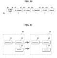
- FIG. 10 is a diagram illustrating an example of UL MU scheduling information to be transmitted through a control subfield of a DL PPDU according to a preferred embodiment of the present invention.
- control information includes length information of a UL PPDU, RU allocation information for the UL PPDU, UL MCS information for the UL PPDU, DL Tx power of an AP, and target receive signal strength indicator (RSSI) information of the AP.
- RSSI target receive signal strength indicator
- other control information can be estimated by an STA based on information of the received DL PPDU without explicit signaling from the AP. Alternatively, predetermined values can be used. Details will be described later.
- the length information of the UL PPDU and the RU allocation information for the UL PPDU is the same as that described above with reference to FIG. 9 .
- FIG. 10 shows that a 5-bit length of Tx power information and a 5-bit length of Rx power information, i.e., total 10 bits of Tx and Rx power information is signaled.
- a UL MCS is illustrated as the information requiring explicit signaling.
- a short length e.g. 2 bits
- any one of four MCSs corresponding to the lowest modulation and coding scheme is selected from among all available MCSs.
- the STA can use predetermined values for omitted information of the UL MU scheduling information.
- the STA can estimate the omitted information using the information of the received DL MU PPDU.
- ACK/BA/M-BA since more robust transmission is generally required unlike an MCS used to transmit data such as a DL MU PPDU, it is difficult to use the MCS applied to the DL MU PPDU.
- a fixed MCS is applied without consideration of a channel state, it may cause performance degradation.
- control field when the control field is configured to include the length information of the UL PPDU, the RU allocation information for the UL PPDU, the UL MCS information for the UL PPDU, the DL Tx power of the AP, and the target RSSI information of the AP as shown in FIG. 10 , a 26-bit length of control information can be configured.
- this control information can be paired with the 4-bit control ID field shown in FIG. 8 in order to satisfy the 30-bit length of subfield.
- the control information subfield of the DL PPDU may not include a CP and LTF type field as shown in FIG. 10 .
- the trigger frame uses two bits for this field, the UL MU PPDU actually uses only two values: 2xLTF + 1.6us CP size and 4xLTF + 3.2us CP size.
- a 1-bit LTF and CP field can be used and in this case, values of the corresponding field are given as follows:
- the STA may be configured to use any one of the two CP and LTF structures according to the received DL PPDU.
- control information subfield may not include DCM (dual carrier modulation) information as shown in FIG. 10 .
- the MCS can be informed through simple 2-bit signaling.
- the STA can determine whether the DCM is applied to the UL MU PPDU by considering the MCS of the DL MU PPDU. That is, when the DCM is applied to the received DL MU PPDU, the STA can determine that the DCM is applied to the UL MU PPDU. Otherwise, the STA may be configured to determine that the DCM is not applied to the UL MU PPDU.
- control information subfield may not include bandwidth information.
- the SAT may determine that a bandwidth of the UL MU PPDU is the same as that of the DL MU PPDU.
- the STA can configure information related to the UL MU PPDU using the information of the received the DL MU PPDU.
- the control information subfield of the DL PPDU may not include spatial reuse information as shown in FIG. 10 . If the control information subfield includes a spatial reuse field defined in the conventional HE-SIG-A, it may have a length of 4 bits. However, the gain obtained by applying the spatial reuse to ACK/BA-M-BA transmission for UL MU data transmission is not greater than that obtained by saving the space for signaling. Thus, according to an embodiment of the present invention, the control information subfield is configured not to include the spatial reuse information and the STA is preferred to disable spatial reuse according to the received DL PPDU.
- control information subfield does not include information on an MU MIMO LTF mode, an STBC, the number of streams, a stream allocation, and a coding type and the STA may set parameters for the MU MIMO LTF mode, the STBC, the number of streams, the stream allocation, and the coding type to '0' according to the received DL PPDU.
- FIG. 10 is not the only way to implement the present invention and other embodiments for the control field of the DL PPDU will be described hereinafter.
- the TXOP field may have a length of 5 to 7 bits.
- the TXOP since the TXOP may not be inserted due to the size limitation, it is also possible to use a 1-bit TXOP field.
- UL MU ACK/BA is transmitted in the last frame of the TXOP (UL TXOP), it is set to '0'.
- the corresponding field is set to '1', it may indicate that the TXOP value is calculated through TXOP operation. In general, it is configured based on the MAC duration of the current/previous frame.
- FIG. 11 is a block diagram for an exemplary configuration of an AP (or a base station) and an STA (or a UE) according to one embodiment of the present invention.
- An AP 100 can include a processor 110, a memory 120, and a transceiver 130.
- An STA 150 can include a processor 160, a memory 170, and a transceiver 180.
- the transceiver 130/180 can transmit/receive a radio signal and implement a physical layer according to IEEE 802 system.
- the processor 110/160 is connected with the transceiver 130/180 and can implement a physical layer and/or a MAC layer according to IEEE 802 system.
- the processor 110/160 is configured to perform an operation according to one or a combination of two or more embodiments of the present invention.
- a module for implementing operations of the AP and the STA according to the various embodiments of the present invention is stored in the memory 120/170 and the module can be executed by the processor 110/160.
- the memory 120/170 can be connected with the processor 110/160 via a well-known media in a manner of being included in the processor 110/160 or being installed in the outside of the processor 110/160.
- Explanation on the AP 100 and explanation on the STA 150 can be respectively applied to a base station and a user equipment in a different wireless communication system (e.g., LTE/LTE-A system).
- a base station e.g., LTE/LTE-A system
- LTE/LTE-A system e.g., LTE/LTE-A system
- the configurations of the AP and the STA as described above may be implemented such that the above-described embodiments can be independently applied or two or more thereof can be simultaneously applied, and description of redundant parts is omitted for clarity.
- the aforementioned embodiments of the present invention can be applied to various wireless communication system including the IEEE 802.11 system.
Landscapes
- Engineering & Computer Science (AREA)
- Signal Processing (AREA)
- Computer Networks & Wireless Communication (AREA)
- Quality & Reliability (AREA)
- Mobile Radio Communication Systems (AREA)
Claims (9)
- Procédé de communication, le procédé étant exécuté par une station, STA, pour un système de réseau local sans fil, WLAN, le procédé comprenant:la réception d'une unité physique de données de protocole, PPDU, de liaison descendante, comprenant:un sous-champ d'informations de commande pour les informations de programmation de la liaison montante, etdes données de liaison descendanteen provenance d'un point d'accès, AP; etla transmission, à l'AP, d'une PPDU de liaison montante comprenant un signal d'accusé de réception en réponse aux données de liaison descendante conformément aux informations de programmation de liaison montante,dans lequel le sous-champ d'informations de commande ne comprend pas d'informations sur la largeur de bande, et dans lequel la STA est configurée pour régler une largeur de bande de la PPDU de liaison montante pour qu'elle soit identique à une largeur de bande de la PPDU de liaison descendante, etdans lequel le sous champ d'informations de commande comprend:des informations de longueur de la PPDU de liaison montante,des informations d'allocation d'unité de ressources, RU, pour la PPDU de liaison montante,des informations de schéma de codage et de modulation, MCS, pour la PPDU de liaison montante,la puissance de transmission de I'AP, etles informations d'indicateur d'intensité de signal, RSSI, de I'AP.
- Procédé selon la revendication 1, dans lequel lors de la réception du PPDU en liaison descendante, la STA est configurée pour modifier une structure de préfixe cyclique, CP, et de champ d'apprentissage long, LTF, en l'une des deux structures suivantes :(1) une structure dans laquelle un 4 x LTF et un 3, 2 CP us CP sont utilisés; et(2) une structure dans laquelle un 2 x LTF et un 1,6 CP us CP sont utilisés.
- Procédé selon la revendication 1 ou 2, dans lequel lors de la réception de la PPDU de liaison descendante, la STA est configurée pour définir les paramètres d'un mode multi-utilisateur, multi-entrée, multi-sortie, MU MIMO LTF, d'un code de bloc spatio-temporel, STBC, d'un nombre de flux, d'une allocation de flux et d'un type de codage sur tous les 0, ce qui signifie que le mode MU MIMO LTF et le STBC ne sont pas utilisés et que les paramètres relatifs au nombre de flux, à l'allocation de flux et au type de codage sont réglés sur 0.
- Procédé selon l'une quelconque des revendications 1 à 3, dans lequel les informations MCS ont une longueur de 2 bits, et dans lequel la STA est configurée pour sélectionner un niveau MCS correspondant aux informations MCS parmi les quatre niveaux MCS les plus bas parmi une pluralité de niveaux MCS prédéterminés de la trame de déclenchement.
- Procédé selon l'une quelconque des revendications 1 à 4, dans lequel la PPDU de liaison montante comprend l'un parmi un signal d'accusé de réception individuel, un signal d'accusé de réception de bloc, BA, et un signal BA multi-STA en réponse aux données de liaison descendante.
- Station, STA, communiquant pour un système de réseau local sans fil, WLAN, la STA comprenant:un émetteur récepteur conçu pour recevoir une unité physique de données de protocole, PPDU, de liaison descendante, comprenant:un sous-champ d'informations de commande pour les informations de programmation de la liaison montante, etdes données de liaison descendanteen provenance d'un point d'accès, AP; etun processeur configuré pour traiter les informations de programmation de la liaison montante et amener l'émetteur-récepteur à transmettre à l'AP une PPDU de liaison montante comprenant un signal d'accusé de réception en réponse aux données de liaison descendante à I'AP,dans lequel le processeur est configuré pour traiter les informations de programmation de la liaison montante en fonction du fait que le sous-champ d'informations de commande ne comprend pas d'informations sur la largeur de bande et que le sous-champ d'informations de commande comprend:des informations de longueur de la PPDU de liaison montante,des informations d'allocation d'unité de ressources (RU) pour la PPDU de liaison montante,des informations de schéma de codage et de modulation (MCS) pour la PPDU de liaison montante,la puissance d transmission de I'AP, etles informations d'indicateur d'intensité de signal (RSSI), de I'AP,dans lequel le processeur est configuré pour régler une largeur de bande de la PPDU de liaison montantes pour qu'elle soit identique à une largeur de bande de la PPDU de liaison descendante.
- STA selon la revendication 6, dans laquelle lorsque le PPDU de liaison descendante est reçue, le processeur est configuré pour modifier une structure de préfixe cyclique, CP, et de champ d'apprentissage long, LTF, en l'une des deux structures:(1) une structure dans laquelle un 4 x LTF et un 3, 2 CP us CP sont utilisés; et(2) une structure dans laquelle un 2 x LTF et un 1,6 CP us CP sont utilisés.
- Procédé de communication, le procédé étant exécuté par un point d'accès, AP, pour un système de réseau local sans fil, WLAN, le procédé comprenant:la transmission d'une unité physique de données de protocole, PPDU, de liaison descendante, comprenant:un sous-champ d'informations de commande pour les informations de programmation de la liaison montante, etdes données de liaison descendanteà une station, STA; etla réception , en provenance de la STA, d'une PPDU de liaison montante comprenant un signal d'accusé de réception en réponse aux données de liaison descendante conformément aux informations de programmation de liaison montante,dans lequel le sous-champ d'informations de commande ne comprend pas d'informations sur la largeur de bande, et dans lequel la STA est configurée pour régler une largeur de bande de la PPDU de liaison montante pour qu'elle soit identique à une largeur de bande de la PPDU de liaison descendante,
etdans lequel le sous champ d'informations de commande comprend:des informations de longueur de la PPDU de liaison montante,des informations d'allocation d'unité de ressources, RU, pour la PPDU de liaison montante,des informations de schéma de codage et de modulation, MCS, pour la PPDU de liaison montante,la puissance de transmission de I'AP, etles informations d'indicateur d'intensité de signal, RSSI, de I'AP. - Point d'accès, AP, communiquant pour une station, STA, pour un système de réseau local sans fil, WLAN, I'AP comprenant:un processeur configuré pour configurer une unité physique de données de protocole, PPDU, de liaison descendante, comprenant:un sous-champ d'informations de commande comprenant des informations de programmation de la liaison montante, etdes données de liaison descendantes; etun émetteur-récepteur configuré pour transmettre le PPDU de liaison descendante à la STA en recevant la PPDU de liaison descendante en provenance du processeur et pour recevoir, en provenance de la STA, une PPDU de liaison montante comprenant un signal d'accusé de réception en réponse aux données de liaison descendante conformément aux informations de programmation de liaison montante,dans lequel le sous-champ d'informations de commande ne comprend pas d'informations sur la largeur de bande, et dans lequel la STA est configurée pour régler une largeur de bande de la PPDU de liaison montante pour qu'elle soit identique à une largeur de bande de la PPDU de liaison descendante,
etdans lequel le processeur est configuré pour configurer le sous champ d'informations de commande pour comprendre:des informations de longueur de la PPDU de liaison montante,des informations d'allocation d'unité de ressources, RU, pour la PPDU de liaison montante,des informations de schéma de codage et de modulation, MCS, pour la PPDU de liaison montante,la puissance de transmission de I'AP, etles informations d'indicateur d'intensité de signal, RSSI, de I'AP.
Applications Claiming Priority (4)
| Application Number | Priority Date | Filing Date | Title |
|---|---|---|---|
| US201662296082P | 2016-02-17 | 2016-02-17 | |
| US201662329172P | 2016-04-28 | 2016-04-28 | |
| PCT/KR2017/000527 WO2017142210A1 (fr) | 2016-02-17 | 2017-01-16 | Procédé destiné à la transmission et à la réception d'un signal d'accusé de réception de liaison montante dans un système de réseau local sans fil et appareil correspondant |
| EP17753371.8A EP3419203B1 (fr) | 2016-02-17 | 2017-01-16 | Procédé destiné à la transmission et à la réception d'un signal d'accusé de réception de liaison montante dans un système de réseau local sans fil et appareil correspondant |
Related Parent Applications (1)
| Application Number | Title | Priority Date | Filing Date |
|---|---|---|---|
| EP17753371.8A Division EP3419203B1 (fr) | 2016-02-17 | 2017-01-16 | Procédé destiné à la transmission et à la réception d'un signal d'accusé de réception de liaison montante dans un système de réseau local sans fil et appareil correspondant |
Publications (4)
| Publication Number | Publication Date |
|---|---|
| EP4262131A2 EP4262131A2 (fr) | 2023-10-18 |
| EP4262131A3 EP4262131A3 (fr) | 2024-01-10 |
| EP4262131B1 true EP4262131B1 (fr) | 2024-08-21 |
| EP4262131C0 EP4262131C0 (fr) | 2024-08-21 |
Family
ID=59626081
Family Applications (2)
| Application Number | Title | Priority Date | Filing Date |
|---|---|---|---|
| EP23195120.3A Active EP4262131B1 (fr) | 2016-02-17 | 2017-01-16 | Procédé d'émission et de réception d'un signal d'accusé de réception de liaison montante dans un système lan sans fil et appareil associé |
| EP17753371.8A Active EP3419203B1 (fr) | 2016-02-17 | 2017-01-16 | Procédé destiné à la transmission et à la réception d'un signal d'accusé de réception de liaison montante dans un système de réseau local sans fil et appareil correspondant |
Family Applications After (1)
| Application Number | Title | Priority Date | Filing Date |
|---|---|---|---|
| EP17753371.8A Active EP3419203B1 (fr) | 2016-02-17 | 2017-01-16 | Procédé destiné à la transmission et à la réception d'un signal d'accusé de réception de liaison montante dans un système de réseau local sans fil et appareil correspondant |
Country Status (4)
| Country | Link |
|---|---|
| US (1) | US10306667B2 (fr) |
| EP (2) | EP4262131B1 (fr) |
| KR (1) | KR101966132B1 (fr) |
| WO (1) | WO2017142210A1 (fr) |
Families Citing this family (9)
| Publication number | Priority date | Publication date | Assignee | Title |
|---|---|---|---|---|
| EP3443793A2 (fr) | 2016-04-12 | 2019-02-20 | Marvell World Trade Ltd. | Transmission multiutilisateur en liaison montante |
| US20180062805A1 (en) * | 2016-08-25 | 2018-03-01 | Po-Kai Huang | Setting of spatial reuse field for he trigger-based ppdu |
| US11337183B2 (en) * | 2019-02-28 | 2022-05-17 | Qualcomm Incorporated | Aggregated control information for a wireless communication network |
| WO2020180007A1 (fr) * | 2019-03-07 | 2020-09-10 | 엘지전자 주식회사 | Transmission de signal à l'aide d'une pluralité d'ap |
| US11737123B2 (en) | 2020-04-23 | 2023-08-22 | Samsung Electronics Co., Ltd. | Communication based on a multi-resource unit in wireless local area network system |
| US11696178B2 (en) | 2020-05-25 | 2023-07-04 | Samsung Electronics Co., Ltd. | Apparatus and method for reducing overhead of signaling field in physical layer convergence protocol in wireless local area network system |
| EP4252486B1 (fr) | 2020-12-24 | 2026-04-29 | Guangdong Oppo Mobile Telecommunications Corp., Ltd. | Procédés et appareils de déclenchement d'une transmission en liaison montante dans des réseaux locaux sans fil |
| EP4262306B1 (fr) * | 2021-01-11 | 2025-06-11 | LG Electronics Inc. | Procédé et dispositif de configuration de champ de réutilisation d'espace dans un système lan sans fil |
| US12348346B2 (en) * | 2023-02-14 | 2025-07-01 | Qualcomm Incorporated | Flexible guard length interval |
Family Cites Families (9)
| Publication number | Priority date | Publication date | Assignee | Title |
|---|---|---|---|---|
| KR20070020033A (ko) * | 2004-05-13 | 2007-02-16 | 코닌클리케 필립스 일렉트로닉스 엔.브이. | Ieee 802.11n에 관한 상이한 데이터 속도를 구비한다중 수신기 집합(mra) |
| KR101400658B1 (ko) * | 2006-12-15 | 2014-05-27 | 톰슨 라이센싱 | Tdma mac 계층에서의 mac 프로토콜 데이터 유닛 집합 |
| US9337961B2 (en) * | 2010-06-15 | 2016-05-10 | Qualcomm Incorporated | Method and apparatus for sending very high throughput WLAN acknowledgment frames |
| JP6262852B2 (ja) * | 2013-11-07 | 2018-01-17 | エルジー エレクトロニクス インコーポレイティド | 無線lanにおけるマルチユーザアップリンク受信方法及び装置 |
| KR20160013820A (ko) * | 2014-07-28 | 2016-02-05 | 뉴라컴 인코포레이티드 | 상향링크 다중 사용자 전송에 응답하는 하향링크 확인응답 |
| WO2016021831A1 (fr) | 2014-08-07 | 2016-02-11 | 엘지전자(주) | Procédé de transmission à multiples utilisateurs dans un système de communication sans fil et dispositif associé |
| US9742544B2 (en) * | 2014-08-08 | 2017-08-22 | Newracom, Inc. | Dynamic inter-frame space processing in high efficiency wireless LAN |
| CN106851848B (zh) * | 2015-12-07 | 2020-06-16 | 华为技术有限公司 | 一种并行传输数据的方法及装置 |
| US10366064B2 (en) * | 2016-01-29 | 2019-07-30 | Intel IP Corporation | Basic service set identifications for using non-default spatial reuse parameters |
-
2017
- 2017-01-16 US US15/772,799 patent/US10306667B2/en active Active
- 2017-01-16 WO PCT/KR2017/000527 patent/WO2017142210A1/fr not_active Ceased
- 2017-01-16 EP EP23195120.3A patent/EP4262131B1/fr active Active
- 2017-01-16 EP EP17753371.8A patent/EP3419203B1/fr active Active
- 2017-01-16 KR KR1020187022689A patent/KR101966132B1/ko active Active
Also Published As
| Publication number | Publication date |
|---|---|
| EP4262131A2 (fr) | 2023-10-18 |
| US10306667B2 (en) | 2019-05-28 |
| KR101966132B1 (ko) | 2019-04-05 |
| WO2017142210A1 (fr) | 2017-08-24 |
| US20180324840A1 (en) | 2018-11-08 |
| EP3419203A4 (fr) | 2019-09-18 |
| EP4262131A3 (fr) | 2024-01-10 |
| EP3419203B1 (fr) | 2023-09-13 |
| KR20180098405A (ko) | 2018-09-03 |
| EP3419203A1 (fr) | 2018-12-26 |
| EP4262131C0 (fr) | 2024-08-21 |
Similar Documents
| Publication | Publication Date | Title |
|---|---|---|
| US10986660B2 (en) | Data transmission method in wireless communication system and device therefor | |
| US10608791B2 (en) | Data transmission method in wireless communication system and device therefor | |
| EP4262131B1 (fr) | Procédé d'émission et de réception d'un signal d'accusé de réception de liaison montante dans un système lan sans fil et appareil associé | |
| US10630515B2 (en) | Data transmission method and apparatus in wireless communication system | |
| EP3185497B1 (fr) | Procédé destiné à une transmission en liaison montante dans un système de communication sans fil, et appareil correspondant | |
| US10200175B2 (en) | Multiuser transreceiving method in wireless communication system and device for same | |
| EP3157300B1 (fr) | Procédé de transmission de données dans un système de communications sans fil, et appareil associé | |
| US20170170937A1 (en) | Method for multi-user uplink data transmission in wireless communication system and device therefor | |
| US20170171878A1 (en) | Method and device for transmitting uplink multi-user data in wireless communication system | |
| GB2596241A (en) | Data transmission method in wireless communication system, and apparatus therefor | |
| EP3264704B1 (fr) | Dispositif et procédé de transmission et de réception dans un système de communication sans fil | |
| WO2016104886A1 (fr) | Procédé et appareil de transmission d'unité de données sur la base d'une trame de déclenchement |
Legal Events
| Date | Code | Title | Description |
|---|---|---|---|
| PUAI | Public reference made under article 153(3) epc to a published international application that has entered the european phase |
Free format text: ORIGINAL CODE: 0009012 |
|
| STAA | Information on the status of an ep patent application or granted ep patent |
Free format text: STATUS: REQUEST FOR EXAMINATION WAS MADE |
|
| 17P | Request for examination filed |
Effective date: 20230904 |
|
| AC | Divisional application: reference to earlier application |
Ref document number: 3419203 Country of ref document: EP Kind code of ref document: P |
|
| AK | Designated contracting states |
Kind code of ref document: A2 Designated state(s): AL AT BE BG CH CY CZ DE DK EE ES FI FR GB GR HR HU IE IS IT LI LT LU LV MC MK MT NL NO PL PT RO RS SE SI SK SM TR |
|
| REG | Reference to a national code |
Ref country code: DE Ref legal event code: R079 Free format text: PREVIOUS MAIN CLASS: H04L0005000000 Ipc: H04L0001000000 Ref country code: DE Ref legal event code: R079 Ref document number: 602017084413 Country of ref document: DE Free format text: PREVIOUS MAIN CLASS: H04L0005000000 Ipc: H04L0001000000 |
|
| PUAL | Search report despatched |
Free format text: ORIGINAL CODE: 0009013 |
|
| AK | Designated contracting states |
Kind code of ref document: A3 Designated state(s): AL AT BE BG CH CY CZ DE DK EE ES FI FR GB GR HR HU IE IS IT LI LT LU LV MC MK MT NL NO PL PT RO RS SE SI SK SM TR |
|
| RIC1 | Information provided on ipc code assigned before grant |
Ipc: H04L 5/00 20060101ALI20231206BHEP Ipc: H04W 84/12 20090101ALI20231206BHEP Ipc: H04L 27/26 20060101ALI20231206BHEP Ipc: H04L 1/00 20060101AFI20231206BHEP |
|
| GRAP | Despatch of communication of intention to grant a patent |
Free format text: ORIGINAL CODE: EPIDOSNIGR1 |
|
| STAA | Information on the status of an ep patent application or granted ep patent |
Free format text: STATUS: GRANT OF PATENT IS INTENDED |
|
| RIC1 | Information provided on ipc code assigned before grant |
Ipc: H04L 5/00 20060101ALI20240227BHEP Ipc: H04W 84/12 20090101ALI20240227BHEP Ipc: H04L 27/26 20060101ALI20240227BHEP Ipc: H04L 1/00 20060101AFI20240227BHEP |
|
| INTG | Intention to grant announced |
Effective date: 20240318 |
|
| GRAS | Grant fee paid |
Free format text: ORIGINAL CODE: EPIDOSNIGR3 |
|
| GRAA | (expected) grant |
Free format text: ORIGINAL CODE: 0009210 |
|
| STAA | Information on the status of an ep patent application or granted ep patent |
Free format text: STATUS: THE PATENT HAS BEEN GRANTED |
|
| AC | Divisional application: reference to earlier application |
Ref document number: 3419203 Country of ref document: EP Kind code of ref document: P |
|
| AK | Designated contracting states |
Kind code of ref document: B1 Designated state(s): AL AT BE BG CH CY CZ DE DK EE ES FI FR GB GR HR HU IE IS IT LI LT LU LV MC MK MT NL NO PL PT RO RS SE SI SK SM TR |
|
| REG | Reference to a national code |
Ref country code: GB Ref legal event code: FG4D |
|
| REG | Reference to a national code |
Ref country code: CH Ref legal event code: EP |
|
| REG | Reference to a national code |
Ref country code: DE Ref legal event code: R096 Ref document number: 602017084413 Country of ref document: DE |
|
| REG | Reference to a national code |
Ref country code: IE Ref legal event code: FG4D |
|
| U01 | Request for unitary effect filed |
Effective date: 20240918 |
|
| U07 | Unitary effect registered |
Designated state(s): AT BE BG DE DK EE FI FR IT LT LU LV MT NL PT RO SE SI Effective date: 20241008 |
|
| PG25 | Lapsed in a contracting state [announced via postgrant information from national office to epo] |
Ref country code: NO Free format text: LAPSE BECAUSE OF FAILURE TO SUBMIT A TRANSLATION OF THE DESCRIPTION OR TO PAY THE FEE WITHIN THE PRESCRIBED TIME-LIMIT Effective date: 20241121 |
|
| PG25 | Lapsed in a contracting state [announced via postgrant information from national office to epo] |
Ref country code: PL Free format text: LAPSE BECAUSE OF FAILURE TO SUBMIT A TRANSLATION OF THE DESCRIPTION OR TO PAY THE FEE WITHIN THE PRESCRIBED TIME-LIMIT Effective date: 20240821 Ref country code: GR Free format text: LAPSE BECAUSE OF FAILURE TO SUBMIT A TRANSLATION OF THE DESCRIPTION OR TO PAY THE FEE WITHIN THE PRESCRIBED TIME-LIMIT Effective date: 20241122 |
|
| PG25 | Lapsed in a contracting state [announced via postgrant information from national office to epo] |
Ref country code: IS Free format text: LAPSE BECAUSE OF FAILURE TO SUBMIT A TRANSLATION OF THE DESCRIPTION OR TO PAY THE FEE WITHIN THE PRESCRIBED TIME-LIMIT Effective date: 20241221 |
|
| PG25 | Lapsed in a contracting state [announced via postgrant information from national office to epo] |
Ref country code: HR Free format text: LAPSE BECAUSE OF FAILURE TO SUBMIT A TRANSLATION OF THE DESCRIPTION OR TO PAY THE FEE WITHIN THE PRESCRIBED TIME-LIMIT Effective date: 20240821 |
|
| PG25 | Lapsed in a contracting state [announced via postgrant information from national office to epo] |
Ref country code: RS Free format text: LAPSE BECAUSE OF FAILURE TO SUBMIT A TRANSLATION OF THE DESCRIPTION OR TO PAY THE FEE WITHIN THE PRESCRIBED TIME-LIMIT Effective date: 20241121 Ref country code: ES Free format text: LAPSE BECAUSE OF FAILURE TO SUBMIT A TRANSLATION OF THE DESCRIPTION OR TO PAY THE FEE WITHIN THE PRESCRIBED TIME-LIMIT Effective date: 20240821 |
|
| PG25 | Lapsed in a contracting state [announced via postgrant information from national office to epo] |
Ref country code: RS Free format text: LAPSE BECAUSE OF FAILURE TO SUBMIT A TRANSLATION OF THE DESCRIPTION OR TO PAY THE FEE WITHIN THE PRESCRIBED TIME-LIMIT Effective date: 20241121 Ref country code: PL Free format text: LAPSE BECAUSE OF FAILURE TO SUBMIT A TRANSLATION OF THE DESCRIPTION OR TO PAY THE FEE WITHIN THE PRESCRIBED TIME-LIMIT Effective date: 20240821 Ref country code: NO Free format text: LAPSE BECAUSE OF FAILURE TO SUBMIT A TRANSLATION OF THE DESCRIPTION OR TO PAY THE FEE WITHIN THE PRESCRIBED TIME-LIMIT Effective date: 20241121 Ref country code: IS Free format text: LAPSE BECAUSE OF FAILURE TO SUBMIT A TRANSLATION OF THE DESCRIPTION OR TO PAY THE FEE WITHIN THE PRESCRIBED TIME-LIMIT Effective date: 20241221 Ref country code: HR Free format text: LAPSE BECAUSE OF FAILURE TO SUBMIT A TRANSLATION OF THE DESCRIPTION OR TO PAY THE FEE WITHIN THE PRESCRIBED TIME-LIMIT Effective date: 20240821 Ref country code: GR Free format text: LAPSE BECAUSE OF FAILURE TO SUBMIT A TRANSLATION OF THE DESCRIPTION OR TO PAY THE FEE WITHIN THE PRESCRIBED TIME-LIMIT Effective date: 20241122 Ref country code: ES Free format text: LAPSE BECAUSE OF FAILURE TO SUBMIT A TRANSLATION OF THE DESCRIPTION OR TO PAY THE FEE WITHIN THE PRESCRIBED TIME-LIMIT Effective date: 20240821 |
|
| U20 | Renewal fee for the european patent with unitary effect paid |
Year of fee payment: 9 Effective date: 20250122 |
|
| PG25 | Lapsed in a contracting state [announced via postgrant information from national office to epo] |
Ref country code: SM Free format text: LAPSE BECAUSE OF FAILURE TO SUBMIT A TRANSLATION OF THE DESCRIPTION OR TO PAY THE FEE WITHIN THE PRESCRIBED TIME-LIMIT Effective date: 20240821 |
|
| PG25 | Lapsed in a contracting state [announced via postgrant information from national office to epo] |
Ref country code: CZ Free format text: LAPSE BECAUSE OF FAILURE TO SUBMIT A TRANSLATION OF THE DESCRIPTION OR TO PAY THE FEE WITHIN THE PRESCRIBED TIME-LIMIT Effective date: 20240821 |
|
| PG25 | Lapsed in a contracting state [announced via postgrant information from national office to epo] |
Ref country code: SK Free format text: LAPSE BECAUSE OF FAILURE TO SUBMIT A TRANSLATION OF THE DESCRIPTION OR TO PAY THE FEE WITHIN THE PRESCRIBED TIME-LIMIT Effective date: 20240821 |
|
| PLBE | No opposition filed within time limit |
Free format text: ORIGINAL CODE: 0009261 |
|
| STAA | Information on the status of an ep patent application or granted ep patent |
Free format text: STATUS: NO OPPOSITION FILED WITHIN TIME LIMIT |
|
| 26N | No opposition filed |
Effective date: 20250522 |
|
| REG | Reference to a national code |
Ref country code: CH Ref legal event code: PL |
|
| PG25 | Lapsed in a contracting state [announced via postgrant information from national office to epo] |
Ref country code: MC Free format text: LAPSE BECAUSE OF FAILURE TO SUBMIT A TRANSLATION OF THE DESCRIPTION OR TO PAY THE FEE WITHIN THE PRESCRIBED TIME-LIMIT Effective date: 20240821 |
|
| GBPC | Gb: european patent ceased through non-payment of renewal fee |
Effective date: 20250116 |
|
| PG25 | Lapsed in a contracting state [announced via postgrant information from national office to epo] |
Ref country code: GB Free format text: LAPSE BECAUSE OF NON-PAYMENT OF DUE FEES Effective date: 20250116 |
|
| PG25 | Lapsed in a contracting state [announced via postgrant information from national office to epo] |
Ref country code: CH Free format text: LAPSE BECAUSE OF NON-PAYMENT OF DUE FEES Effective date: 20250131 |
|
| PG25 | Lapsed in a contracting state [announced via postgrant information from national office to epo] |
Ref country code: IE Free format text: LAPSE BECAUSE OF NON-PAYMENT OF DUE FEES Effective date: 20250116 |
|
| U20 | Renewal fee for the european patent with unitary effect paid |
Year of fee payment: 10 Effective date: 20260122 |