EP4262167A1 - Système et procédé de gestion d'infrastructure - Google Patents
Système et procédé de gestion d'infrastructure Download PDFInfo
- Publication number
- EP4262167A1 EP4262167A1 EP23168053.9A EP23168053A EP4262167A1 EP 4262167 A1 EP4262167 A1 EP 4262167A1 EP 23168053 A EP23168053 A EP 23168053A EP 4262167 A1 EP4262167 A1 EP 4262167A1
- Authority
- EP
- European Patent Office
- Prior art keywords
- component
- infrastructure
- information
- management
- location
- Prior art date
- Legal status (The legal status is an assumption and is not a legal conclusion. Google has not performed a legal analysis and makes no representation as to the accuracy of the status listed.)
- Granted
Links
Images










Classifications
-
- G—PHYSICS
- G06—COMPUTING OR CALCULATING; COUNTING
- G06F—ELECTRIC DIGITAL DATA PROCESSING
- G06F11/00—Error detection; Error correction; Monitoring
- G06F11/30—Monitoring
- G06F11/3003—Monitoring arrangements specially adapted to the computing system or computing system component being monitored
- G06F11/3006—Monitoring arrangements specially adapted to the computing system or computing system component being monitored where the computing system is distributed, e.g. networked systems, clusters, multiprocessor systems
-
- H—ELECTRICITY
- H04—ELECTRIC COMMUNICATION TECHNIQUE
- H04L—TRANSMISSION OF DIGITAL INFORMATION, e.g. TELEGRAPHIC COMMUNICATION
- H04L41/00—Arrangements for maintenance, administration or management of data switching networks, e.g. of packet switching networks
- H04L41/12—Discovery or management of network topologies
-
- G—PHYSICS
- G06—COMPUTING OR CALCULATING; COUNTING
- G06F—ELECTRIC DIGITAL DATA PROCESSING
- G06F11/00—Error detection; Error correction; Monitoring
- G06F11/30—Monitoring
- G06F11/3065—Monitoring arrangements determined by the means or processing involved in reporting the monitored data
-
- G—PHYSICS
- G06—COMPUTING OR CALCULATING; COUNTING
- G06K—GRAPHICAL DATA READING; PRESENTATION OF DATA; RECORD CARRIERS; HANDLING RECORD CARRIERS
- G06K7/00—Methods or arrangements for sensing record carriers, e.g. for reading patterns
- G06K7/10—Methods or arrangements for sensing record carriers, e.g. for reading patterns by electromagnetic radiation, e.g. optical sensing; by corpuscular radiation
- G06K7/10544—Methods or arrangements for sensing record carriers, e.g. for reading patterns by electromagnetic radiation, e.g. optical sensing; by corpuscular radiation by scanning of the records by radiation in the optical part of the electromagnetic spectrum
- G06K7/10821—Methods or arrangements for sensing record carriers, e.g. for reading patterns by electromagnetic radiation, e.g. optical sensing; by corpuscular radiation by scanning of the records by radiation in the optical part of the electromagnetic spectrum further details of bar or optical code scanning devices
- G06K7/10861—Methods or arrangements for sensing record carriers, e.g. for reading patterns by electromagnetic radiation, e.g. optical sensing; by corpuscular radiation by scanning of the records by radiation in the optical part of the electromagnetic spectrum further details of bar or optical code scanning devices sensing of data fields affixed to objects or articles, e.g. coded labels
-
- H—ELECTRICITY
- H04—ELECTRIC COMMUNICATION TECHNIQUE
- H04L—TRANSMISSION OF DIGITAL INFORMATION, e.g. TELEGRAPHIC COMMUNICATION
- H04L41/00—Arrangements for maintenance, administration or management of data switching networks, e.g. of packet switching networks
- H04L41/22—Arrangements for maintenance, administration or management of data switching networks, e.g. of packet switching networks comprising specially adapted graphical user interfaces [GUI]
Definitions
- the following relates to a system, method, and non-transitory computer readable medium including instructions for management of equipment and components found in a telecommunications or data center infrastructure.
- Datacenters and telecommunication rooms are filled with computing, storage, and networking systems that include physical infrastructure such as server cabinets, telecom racks, patch panels, fiber cassettes and cable managers.
- Many datacenter managers and telecom operators create digital models of their rooms using DCIM (Data Center Infrastructure Management) solutions (e.g., software applications) to document the components in their rooms to assist in remote management and troubleshooting of issues that may arise.
- DCIM Data Center Infrastructure Management
- Creating digital representations of physical equipment may require large amounts of data that must be manually entered. This time-consuming process can easily introduce errors and any updates to the physical location requires subsequent manual data entry to update physical changes to the digital copy, which is a significant drain of enterprise resources.
- a system for management of telecommunication or data center infrastructure including a plurality of components.
- the system may comprise a scanner which may be configured to scan a unique identifier attached to a component of the infrastructure, and a mobile computing device which may comprise a processor, a data storage medium storing machine readable instructions, a communication unit, and a user interface including a display.
- the mobile computing device may be configured to execute the machine readable instructions to (i) receive, from the scanner, a component identifier associated with the component obtained via a scan of the unique identifier attached to the component, (ii) associate the component identifier with a location of the component in the infrastructure, (iii) display, on the user interface, the component identifier associated with the location of the component, and (iv) export, via the communication unit, the location of the component to a management solution for use in management of the component in the plurality of components of the infrastructure.
- DCIM solutions are a collection of tools designed to provide proactive failure avoidance, planning capabilities, and cost savings to operators of data centers that include equipment such as fiber cable management equipment, copper cable management equipment, audio/visual equipment, or the like (hereinafter generally referred to as "data centers").
- data centers include equipment such as fiber cable management equipment, copper cable management equipment, audio/visual equipment, or the like.
- Features provided by a DCIM solution may include monitoring critical infrastructure of a data center such as power and cooling systems for analysis and cost reduction, documenting and managing physical infrastructure such as equipment inventory within a data center, or data and power connectivity to diagnose problems that may arise in a data center, work order creation and processing for physical equipment moves, adds, and changes.
- the DCIM solution described herein includes software, hardware, and/or circuitry for implementing the features of the DCIM solution described herein.
- FIG. 23 shows a flowchart 2300 describing an exemplary method of documenting equipment and cable infrastructure locations and inputting product information.
- such a method includes manually identifying 120 cable locations, manually documenting 122 cable location information in the field, looking up 124 cabling product information at a manufacturer website, manually entering 126 cable location information into a DCIM solution, and manually entering 128 cable product information into the DCIM solution.
- Examples of data that may be entered manually into a DCIM solution might be: equipment location in a datacenter rack (e.g., rack unit (RU) location or other location in a rack or cabinet of equipment such as a vertical power distribution unit (PDU) mounted in a cabinet's rear left compartment), type of equipment (e.g., server, network switch, PDU, uninterruptable power supply (UPS)), equipment specific information for each type of equipment (e.g., PDU information might contain the following: number of outlets, outlet type, power rating, plug type), cable end locations for network cables, cable end locations for power cables, cable product information, cable length information, cable connector type information, or other equipment found in the data center.
- equipment location in a datacenter rack e.g., rack unit (RU) location or other location in a rack or cabinet of equipment such as a vertical power distribution unit (PDU) mounted in a cabinet's rear left compartment
- type of equipment e.g., server, network switch, PDU, uninterruptable power supply (UPS)
- the present disclosure describes a DCIM solution for providing more efficient and resource saving solutions for the management of equipment and components found in a data center.
- a cable management solution is disclosed for obtaining data on cable attributes within a data center, where the cabling data is then provided as inputs to the DCIM solution for the DCIM solution to implement the DCIM features disclosed herein.
- the DCIM solution described herein may include the hardware, software, and/or circuitry for implementing the features attributed to it as described herein.
- the present DCIM solution reduces the amount of time spent documenting physical infrastructure and provides product information without manual data entry.
- unique identifiers are placed onto data center equipment, and intelligent software is utilized to provide physical infrastructure documentation without the inconvenience and/or problems associated with manually entering product information.
- the DCIM solution can then reference other saved information to validate equipment or audit installations.
- the disclosed equipment management solution includes software, hardware, and/or circuitry for implementing the features for identifying and documenting cables, network cabinets, telecommunication racks, and other data center equipment according to the present disclosure, as well as any other features described herein.
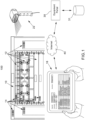
- the equipment management solution may be used in a system 100 that includes infrastructure equipment 12 having a unique identifier 14 (e.g., barcode or QR code) attached.
- the infrastructure equipment 12 may include, but not be limited to: cabinets 10, telecom racks, fiber trays, fiber cassettes, copper and fiber patch panels, plug packs, cable managers, power distribution units, or any other equipment found in a data center.
- the system 100 also includes a personal computer or mobile computing device 16 having a user interface including a display and executing application software according to the present disclosure.
- the equipment management solution may include and/or be an extension of the cable management solution for obtaining cable related information described in U.S. Patent Application No. 17/191,984 (now U.S. Patent No. 11,347,955 issued May 31, 2022 ), the entirety of which is hereby incorporated by reference herein.
- the system 100 also includes a common barcode scanner 22 configured to communicate via Bluetooth, universal serial bus (USB), serial connection, Wi-Fi, radio-frequency (RF), or other known data communication protocol, to the mobile computing device 16 running the application software of the present disclosure.
- a common barcode scanner 22 configured to communicate via Bluetooth, universal serial bus (USB), serial connection, Wi-Fi, radio-frequency (RF), or other known data communication protocol, to the mobile computing device 16 running the application software of the present disclosure.
- USB universal serial bus
- RF radio-frequency
- the system 100 utilizes an internet connection 40 to communicate with an equipment portal (e.g., equipment manufacturer internet portal) to download product information via an appropriate application programming interface (API), which may be a Representational State Transfer (REST) or any other suitable API.
- An equipment portal e.g., equipment manufacturer internet portal
- API application programming interface
- the product information may be stored on a database 31 operated or in control by the equipment portal.
- the product information may be stored on a memory storage included on the mobile computing device 16.
- the system 100 may further include a mobile printer 26 for printing unique identifier labels, as shown in FIGs. 3 and 8 .
- the mobile printer 26 enables a user to print labels with the unique identifier 14 while working in the field during an installation or maintenance work job.
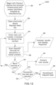
- FIG. 11 shows a flowchart 1100 including steps for implementing an exemplary process for documenting a cabinet, telecommunication rack, or other equipment by the equipment management solution, according to some embodiments.
- the process described by the flowchart 1100 may be referred to as a "Scan Mode", and include the following processes implemented by a processor executing instructions stored on a non-transitory memory included on a computing device (e.g., mobile computing device 16 as shown, for example, in FIG. 2 ):
- This process may be continued until all devices in the cabinet/rack are scanned (90).
- a user may also determine or decide whether to overwrite the previously saved file with any new results from the verification scan (92), or alternatively discard any such new results (94).
- the new results along with product specific information can be saved or exported to an excel spreadsheet or a comma separated values file for import into DCIM or other management systems (96).
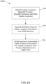
- FIG. 24 shows a flowchart 2400 illustrating an exemplary method of documenting equipment and cable infrastructure locations and inputting product information according to a non-limiting exemplary embodiment of the equipment management solution.
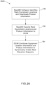
- FIG. 25 shows a flowchart 2500 illustrating another exemplary method of documenting equipment and cable infrastructure locations and inputting product information according to a non-limiting exemplary embodiment of the equipment management solution.
- the software application of the equipment management solution running on the mobile computing device 16 may be used in conjunction with unique barcode identifiers attached to physical infrastructure products to identify and record location information (130, 140).
- unique barcode identifiers attached to physical infrastructure products identify and record location information (130, 140).
- API product information from a product manufacturer's API gateway may be downloaded by the application software of the equipment management solution (132) and exported to the DCIM solution (134), or exported to the DCIM solution first (142) and then the DCIM solution will handle downloading the product information from the product manufacturer's API gateway (144).
- Both methods described by flowchart 2400 and flowchart 2500 may be utilized and/or be interchangeable as they both provide the same result of the DCIM solution having API product information for physical infrastructure products without the need to manually enter the same data.
- the mobile computing device 16 may include a communication unit (e.g., network interface 240) for transmitting and/or receiving wireless or wired signals for communicating over any suitable communication system or systems with a scanner, API, DCIM, or any other unit, controller, device, component, mechanism, module, system, subsystem, gateway, application, software, solution or the like, which communication system or systems may include Bluetooth, Wi-Fi, RF, cellular, internet, telecommunication, and/or any other wireless or wired communication system or systems.
- a communication unit e.g., network interface 240
- a communication unit e.g., network interface 240
- the mobile computing device 16 may include a communication unit (e.g., network interface 240) for transmitting and/or receiving wireless or wired signals for communicating over any suitable communication system or systems with a scanner, API, DCIM, or any other unit, controller, device, component, mechanism, module, system, subsystem, gateway, application, software, solution or the like, which communication system or systems may include Bluetooth, Wi-Fi,
- results data can be exported to the DCIM solution running on the DCIM system for analysis, inventory reporting, and documentation.
- application results may include but are not limited to: equipment location, equipment type, equipment specific manufacturing information (e.g., for PDU: number of outlets, outlet type, power rating, plug type, certifications, image of product), cable end locations for network cables, cable end locations for power cables, cable specific manufacturing information (e.g., for network cable: cable type, cable length, connector type, cable color, cable rating, images of product, etc.)
- FIG. 26 shows a flowchart 2600 describing an exemplary process to dynamically create rack elevation diagrams according to one non-limiting exemplary embodiment of the present disclosure.
- the equipment management solution imports (e.g., downloads) the above-noted results data including the product information (150), and then exports this results data to the DCIM solution (152).
- the DCIM solution is enabled with the information to dynamically build or create rack elevation and connectivity diagrams with detailed product information (154). This provides a more efficient DCIM solution that does not require the DCIM user to look up and manually enter the same data for creating these diagrams. In this way, the equipment management solution described herein eliminates the need for manual data entry and provides a method to automatically create rack elevation diagrams with detailed product information for documenting data center physical infrastructure installations.
- the DCIM solution can combine individual cable location result files together from the equipment management solution to dynamically create end-to-end network channel and power chain documentation.
- a DCIM solution can correlate product information about individual components downloaded from an API gateway to provide information about end-to-end network channels and power chains such as overall channel length and performance.
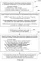
- FIG. 27 shows a flowchart 2700 describing an exemplary process to dynamically create an end-to-end network channel and power chain with product information according to one non-limiting exemplary embodiment of the present disclosure.
- the equipment management solution identifies and documents network and power connectivity locations and cable information (160), as well as then exports such cable location information to the DCIM solution (162).
- the DCIM solution maps network connections and can join individual connection links to create full network channel or power chain mappings of all connections that make and end-to-end network channel (164).
- the DCIM solution may use cable specific information (e.g., lengths or performance of individual cables comprising a channel) to provide lengths or performance of the entire cable channel as a whole (168).
- cable specific information e.g., lengths or performance of individual cables comprising a channel
- FIG. 17 illustrates an exemplary network channel 108 comprised of individual infrastructure components for use with non-limiting exemplary embodiments of the present disclosure
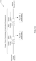
- FIG. 18 illustrates an exemplary electrical power chain 110 comprised individual infrastructure components for use with non-limiting exemplary embodiments of the present disclosure.
- a DCIM solution is configured to correlate cable connectivity information and component wiring method information provided by the application software of the cable management solution disclosed herein with product information downloaded from a manufacturer's API gateway to automatically generate cabling diagrams with fiber and channel mapping in advanced network cabling scenarios that consist of one-to-many components.
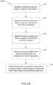
- FIG. 28 shows a flowchart 2800 describing an exemplary process to dynamically create end-to-end network channels with fiber mapping and wiring method information according to one non-limiting exemplary embodiment of the present disclosure.
- advanced network cabling scenarios may utilize one-to-many physical cabling solutions which require additional information about the product and the wiring method to provide accurate fiber or channel mapping in a solution.
- Some examples where one-to-many connectivity products require connection mapping information about a device may include but are not limited to:
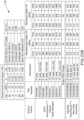
- FIG. 16 shows a table illustrating wiring methods 106 for a fiber cassette for use with non-limiting exemplary embodiments of the present disclosure
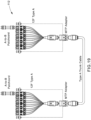
- FIG. 19 shows an exemplary method 112 for wiring a connector to a fiber cassette for use in non-limiting exemplary embodiments of the present disclosure.
- the application software of the equipment management solution can scan a unique identifier on a one-to-many type wiring component to document its physical location and can use the unique identifier with a public facing API to download product knowledge of its wiring method.
- the wiring method information of a component can be combined with a component's associated connections to automatically create end-to-end network channel connectivity maps with fiber mapping and wiring method information.
- FIG. 20 illustrates dynamically created fiber mapping 114 using results of an exemplary software application according to one non-limiting exemplary embodiment of the present disclosure.
- the application software of the equipment management solution identifies and documents cable location information (170) as well as rack unit location information for fiber cassettes (172), and exports such location information to the DCIM solution (174).
- the DCIM solution combines component information with fiber mapping and wiring methods information to dynamically create an end-to-end network channel (178).
- the DCIM solution is configured to calculate a cable routing product's usage percentage or capacity for new cables based on cable assignment information inputted by user, cable and rack location information imported from the application software of the equipment management solution disclosed herein, and product information downloaded from a manufacturers' API.
- FIG. 29 shows a flowchart 2900 illustrating an exemplary process to dynamically calculate cable capacity according to one non-limiting exemplary embodiment of the present disclosure.
- the application software of the equipment management solution may record location information about cable pathways products such as a cable manager or fiber runner and may download product information to determine a product's capacity for holding cables.
- FIG. 21 illustrates a perspective view of an exemplary cable manager 116 for use with non-limiting exemplary embodiments of the present disclosure.
- a DCIM user may assign individual cables to a cable pathway product in a rack elevation such as a cable manager 116 or a fiber runner within the DCIM solution (184).
- the DCIM solution may download product information such as cable manager information and cable diameter information from an API for a cable manager's assigned cables to calculate total cable volumes (186).
- the DCIM solution is configured to compare these cable volumes to the cable holding capacity of a cable manager 116 to dynamically provide a fill percentage of the cable manager 116 or its available capacity for new cables (188).
- the present DCIM solution thus could replace the need for manual spreadsheet capacity calculators which are difficult to operate and provides a method to document cable capacity without manual data entry.
- FIG. 22 illustrates a cable capacity calculator 118 for manual calculation of cable capacity.
- DCIM solutions are configured to import results data from the equipment management solution to build intelligent workflows for mobile devices that include step-by-step installation instructions with installation validation and product information including but not limited to: product photos, product installation guides, and user manuals.
- FIG. 30 shows a flowchart 3000 illustrating an exemplary method for work order creation and/or completion according to one non-limiting exemplary embodiment of the present disclosure.
- a DCIM user begins creating an intelligent work order by virtually moving, adding, or changing server/network equipment, cabling components, network/power connections, or other components to a virtual network cabinet/telecom rack/server enclosure represented in the DCIM solution (190).
- the DCIM user specifies cable type, products, and equipment to be used and locations to be installed/removed.
- the DCIM solution combines move/add/change data manually inputted by the user, products specified for use, and product information downloaded via an API gateway to create an intelligent work order with rack elevation diagrams (192), where these diagrams are created from product images (e.g., front view of telecom rack elevation) that visually display component locations, sequential step-by-step installation instructions with validation using the software relating to the equipment management solution and a barcode scanner 22, and/or other installation support documents like product photos, product installation guides, or user manuals.
- product images e.g., front view of telecom rack elevation
- product images e.g., front view of telecom rack elevation
- sequential step-by-step installation instructions with validation using the software relating to the equipment management solution and a barcode scanner 22, and/or other installation support documents like product photos, product installation guides, or user manuals.
- these intelligent workflows can be sent or exported by the DCIM system to the mobile computing device 16 running the application software of the equipment management solution for installation guidance in the field (194).
- Intelligent workflows may be stored locally on the mobile computing device 16 for use when no network access is available.
- the application software of the equipment management solution running on the mobile computing device 16 can display the rack elevation diagrams of a workflow and an on-site technicians can follow the step-by-step instructions for that workflow (196).
- the application software of the equipment management solution and the barcode scanner 22 may be used to validate equipment location, cable location, and/or proper product has been installed by scanning product manufacturer's unique identifiers on products (196).
- the personal computer, mobile computing device 16, barcode scanner 22, and/or any other unit, module, controller, system, subsystem, mechanism, device, component, gateway, application, solution, software, algorithm, step, function, operation, or the like described herein may comprise and/or be implemented in or by appropriate circuitry, such as one or more appropriately programmed processors (e.g., one or more microprocessors including central processing units (CPU)) and associated memory or data storage medium, which may include stored operating system software and/or application software including computer or machine readable instructions executable by the processor(s) for controlling operation thereof and for performing the particular algorithms represented by the various functions and/or operations described herein, including interaction and/or communication between and/or cooperation with each other.
- processors e.g., one or more microprocessors including central processing units (CPU)
- CPU central processing units
- application software including computer or machine readable instructions executable by the processor(s) for controlling operation thereof and for performing the particular algorithms represented by the various functions and/or operations described herein, including interaction and/or communication
- processors or several such processors and/or circuitry and/or hardware may also be distributed among several separate computers, units, modules, controllers, systems, subsystems, mechanisms, devices, components, gateways or the like. It is also noted that additional details, benefits, and advantages concerning, related to, or resulting from the non-limiting exemplary embodiments of the present disclosure are set forth in the attached appendix, which is part of the present disclosure and incorporated herein by reference.
- FIG. 2 shows a block diagram of an exemplary computer architecture for a computing device system 200.
- the computing device system 200 may be representative of the components included in the mobile computing device 16 or other computing device disclosed herein for implementing one or more of the features relating to the cable management solution and/or the DCIM solution.
- the computing device system 200 may additionally include software, hardware, and/or circuitry for implementing attributed features as described herein.
- the computing device system 200 includes a processor 210, a main memory 220, a static memory 230, an output device 250 (e.g., a display or speaker), an input device 260, and a storage device 270, communicating via a bus 201.
- the bus 201 may represent one or more busses, e.g., USB, PCI, ISA (Industry Standard Architecture), X-Bus, EISA (Extended Industry Standard Architecture), or any other appropriate bus and/or bridge (also called a bus controller).
- the processor 210 represents a central processing unit of any type of architecture, such as a CISC (Complex Instruction Set Computing), RISC (Reduced Instruction Set Computing), VLIW (Very Long Instruction Word), or a hybrid architecture, although any appropriate processor may be used.
- the processor 210 executes instructions 221, 231, 272 stored on one or more of the main memory 220, static memory 230, or storage device 270, respectively.
- the processor 210 may also include portions of the computing device system 200 that control the operation of the entire computing device system 200.
- the processor 210 may also represent a controller that organizes data and program storage in memory and transfers data and other information between the various parts of the computing device system 200.
- the processor 210 is configured to receive input data and/or user commands through input device 260 or received from a network 202 through a network interface 240.
- Input device 260 may be a keyboard, mouse or other pointing device, trackball, scroll, button, touchpad, touch screen, keypad, microphone, speech recognition device, video recognition device, accelerometer, gyroscope, global positioning system (GPS) transceiver, or any other appropriate mechanism for the user to input data to computing device system 200 and control operation of computing device system 200.
- Input device 260 as illustrated in FIG. 2 may be representative of any number and type of input devices.
- the processor 210 may also communicate with other computer systems via the network 202 to receive control commands or instructions 221, 231, 272, where processor 210 may control the storage of such control commands or instructions 221, 231, 272 into any one or more of the main memory 220 (e.g., random access memory (RAM)), static memory 230 (e.g., read only memory (ROM)), or the storage device 270.
- the processor 210 may then read and execute the instructions 221, 231, 272 from any one or more of the main memory 220, static memory 230, or storage device 270.
- the instructions 221, 231, 272 may also be stored onto any one or more of the main memory 220, static memory 230, or storage device 270 through other sources.
- the instructions 221, 231, 272 may correspond to, for example, instructions for implementing the cable management and/or DCIM solution to track and manage the data center equipment within the system 100 illustrated in FIG. 1 .
- computing device system 200 is represented in FIG. 2 as a single processor 210 and a single bus 201, the disclosed embodiments apply equally to computing device system that may have multiple processors and to computing device system that may have multiple busses with some or all performing different functions in different ways.
- the storage device 270 represents one or more mechanisms for storing data.
- the storage device 270 may include a computer readable medium 271 such as read-only memory (ROM), RAM, non-volatile storage media, optical storage media, flash memory devices, and/or other machine-readable media. In other embodiments, any appropriate type of storage device may be used. Although only one storage device 270 is shown, multiple storage devices and multiple types of storage devices may be present.
- the computing device system 200 is drawn to contain the storage device 270, it may be distributed across other computer systems that are in communication with the computing device system 200, such as a server in communication with the computing device system 200. For example, when the computing device system 200 is representative of the mobile computing device 16, the storage device 270 may be distributed across to include a remote database (e.g., database 31).
- a remote database e.g., database 31
- the storage device 270 may include a controller (not shown) and a computer readable medium 271 storing instructions 272 capable of being executed by the processor 210 to carry out the cable management and/or DCIM solution, as described herein. In another embodiment some, or all, the functions are carried out via hardware in lieu of a processor-based system.
- the included controller is a web application browser, but in other embodiments the controller may be a database system, a file system, an electronic mail system, a media manager, an image manager, or may include any other functions capable of accessing data items.
- the output device 250 is configured to present information to the user.
- the output device 250 may be a display such as a liquid crystal display (LCD), a gas or plasma-based flat-panel display, or a traditional cathode-ray tube (CRT) display or other well-known type of display that may, or may not, also include a touch screen capability.
- the output device 250 may function to display a graphical user interface (GUI) such as the GUI for enabling a user to implement the cable management and/or DCIM solution, as described herein.
- GUI graphical user interface
- the output device 250 may be a speaker configured to output audible information to the user.
- any combination of output devices may be represented by the output device 250.
- Computing device system 200 also includes the network interface 240 that allows communication with other computers via the network 202, where the network 202 may be any suitable network and may support any appropriate protocol suitable for communication to/from computing device system 200.
- the network 202 may support wireless communications.
- the network 202 may support hard-wired communications, such as a telephone line or cable.
- the network 202 may support the Ethernet IEEE (Institute of Electrical and Electronics Engineers) 802.3x specification.
- the network 202 may be the Internet (e.g., the internet connection 40 illustrated in FIG. 1 ) and may support IP (Internet Protocol).
- the network 202 may be a local area network (LAN) or a wide area network (WAN).
- LAN local area network
- WAN wide area network
- the network 202 may be a hotspot service provider network. In another embodiment, network 202 may be an intranet. In another embodiment, the network 202 may be a GPRS (General Packet Radio Service) network. In another embodiment, the network 202 may be any appropriate cellular data network or cell-based radio network technology. In another embodiment, the network 202 may be an IEEE 802.11 wireless network. In another embodiment, the network 202 may be representative of an Internet of Things (IoT) network. In still another embodiment, the network 202 may be any suitable network or combination of networks. Although one network 202 is shown in FIG. 2 , the network 202 may be representative of any number of networks (of the same or different types) that may be utilized.
- IoT Internet of Things
- the network interface 240 provides the computing device system 200 with connectivity to the network 202 through any compatible communications protocol.
- the network interface 240 sends and/or receives data from the network 202 via a wireless or wired transceiver 241.
- the transceiver 241 may be a cellular frequency, radio frequency (RF), infrared (IR), Bluetooth, or any of a number of known wireless or wired transmission systems capable of communicating with the network 202 or other computer device having some or all of the features of the computing device system 200.
- the network interface 240 as illustrated in FIG. 2 may be representative of a single network interface card configured to communicate with one or more different data sources.
- the network interface 240 may be representative of AV related communication ports such as high-definition multimedia interface (HDMI), DisplayPort, or mini DisplayPort (MDP), as well as data communication ports such as ethernet, universal serial bus (USB), power over ethernet (POE), or single pair ethemet (SPE).
- HDMI high-definition multimedia interface
- MDP mini DisplayPort
- data communication ports such as ethernet, universal serial bus (USB), power over ethernet (POE), or single pair ethemet (SPE).
- the computing device system 200 may be implemented using any suitable hardware and/or software, such as a personal computer or other electronic computing device.
- the computing device system 200 may also be a smartphone, portable computer, laptop, tablet or notebook computer, PDA, appliance, IP telephone, server computer device, AV gateway, cloud service platform, or mainframe computer.
Landscapes
- Engineering & Computer Science (AREA)
- Physics & Mathematics (AREA)
- Theoretical Computer Science (AREA)
- General Physics & Mathematics (AREA)
- Quality & Reliability (AREA)
- Electromagnetism (AREA)
- Computing Systems (AREA)
- General Engineering & Computer Science (AREA)
- General Health & Medical Sciences (AREA)
- Health & Medical Sciences (AREA)
- Toxicology (AREA)
- Computer Vision & Pattern Recognition (AREA)
- Artificial Intelligence (AREA)
- Mathematical Physics (AREA)
- Computer Networks & Wireless Communication (AREA)
- Signal Processing (AREA)
- Stored Programmes (AREA)
- Telephonic Communication Services (AREA)
- Testing And Monitoring For Control Systems (AREA)
- Computer And Data Communications (AREA)
Priority Applications (1)
| Application Number | Priority Date | Filing Date | Title |
|---|---|---|---|
| EP25185044.2A EP4597969A3 (fr) | 2022-04-14 | 2023-04-14 | Système et procédé de gestion d'infrastructure |
Applications Claiming Priority (2)
| Application Number | Priority Date | Filing Date | Title |
|---|---|---|---|
| US202263330911P | 2022-04-14 | 2022-04-14 | |
| US18/127,690 US12399794B2 (en) | 2022-04-14 | 2023-03-29 | Infrastructure management system and method |
Related Child Applications (2)
| Application Number | Title | Priority Date | Filing Date |
|---|---|---|---|
| EP25185044.2A Division EP4597969A3 (fr) | 2022-04-14 | 2023-04-14 | Système et procédé de gestion d'infrastructure |
| EP25185044.2A Division-Into EP4597969A3 (fr) | 2022-04-14 | 2023-04-14 | Système et procédé de gestion d'infrastructure |
Publications (3)
| Publication Number | Publication Date |
|---|---|
| EP4262167A1 true EP4262167A1 (fr) | 2023-10-18 |
| EP4262167B1 EP4262167B1 (fr) | 2025-08-06 |
| EP4262167C0 EP4262167C0 (fr) | 2025-08-06 |
Family
ID=86052060
Family Applications (2)
| Application Number | Title | Priority Date | Filing Date |
|---|---|---|---|
| EP23168053.9A Active EP4262167B1 (fr) | 2022-04-14 | 2023-04-14 | Système et procédé de gestion d'infrastructure |
| EP25185044.2A Pending EP4597969A3 (fr) | 2022-04-14 | 2023-04-14 | Système et procédé de gestion d'infrastructure |
Family Applications After (1)
| Application Number | Title | Priority Date | Filing Date |
|---|---|---|---|
| EP25185044.2A Pending EP4597969A3 (fr) | 2022-04-14 | 2023-04-14 | Système et procédé de gestion d'infrastructure |
Country Status (2)
| Country | Link |
|---|---|
| US (2) | US12399794B2 (fr) |
| EP (2) | EP4262167B1 (fr) |
Families Citing this family (1)
| Publication number | Priority date | Publication date | Assignee | Title |
|---|---|---|---|---|
| US12191640B2 (en) * | 2022-03-18 | 2025-01-07 | CyberSecure IPS, LLC | Facilitating installation of cables within datacenters |
Citations (4)
| Publication number | Priority date | Publication date | Assignee | Title |
|---|---|---|---|---|
| US20120316778A1 (en) * | 2011-06-13 | 2012-12-13 | Vcc Engineering Llc | System and method for aligning a particular passenger with a unique vehicle |
| EP3399698A1 (fr) * | 2017-05-04 | 2018-11-07 | Servicenow, Inc. | Inventaire automatisé pour dispositifs iot |
| WO2020219910A1 (fr) * | 2019-04-25 | 2020-10-29 | Trackonomy Systems, Inc. | Installation, déploiement, maintenance et fonctionnement de réseaux de capteurs sans fil |
| US20210279437A1 (en) * | 2020-03-09 | 2021-09-09 | Panduit Corp. | Cable Management System and Method |
Family Cites Families (28)
| Publication number | Priority date | Publication date | Assignee | Title |
|---|---|---|---|---|
| US5704189A (en) | 1993-11-09 | 1998-01-06 | Collier; William R. | Methods and apparatus for installing conductor cables in rigid building structures |
| US20020008621A1 (en) | 2000-01-06 | 2002-01-24 | Isogon Corporation | Method and system for determining the inventory and location of assets |
| US20020095487A1 (en) | 2001-01-18 | 2002-07-18 | Robert Day | System for registering, locating, and identifying network equipment |
| GB2393549B (en) | 2002-09-25 | 2006-05-31 | Cormant Technologies Inc | Cabling system |
| US20040099736A1 (en) | 2002-11-25 | 2004-05-27 | Yoram Neumark | Inventory control and identification method |
| US8117092B2 (en) | 2003-07-09 | 2012-02-14 | Hewlett-Packard Development Company, L.P. | Inventory management of components |
| IL157203A (en) | 2003-07-31 | 2010-12-30 | Rit Techn Ltd | Management of large scale cabling systems |
| US20090195384A1 (en) | 2008-02-01 | 2009-08-06 | Honeywell International Inc. | System and method for inventory management |
| US8264354B2 (en) | 2009-10-14 | 2012-09-11 | Attend Systems, Llc | Data center equipment location and monitoring system |
| US20120166693A1 (en) * | 2010-07-26 | 2012-06-28 | Raritan Americas, Inc. | Intelligent Asset Management System |
| US9064022B2 (en) | 2011-05-17 | 2015-06-23 | Adc Telecommunications, Inc. | Component identification and tracking system for telecommunication networks |
| US8914495B2 (en) | 2011-06-07 | 2014-12-16 | International Business Machines Corporation | Automatically detecting and locating equipment within an equipment rack |
| US9965564B2 (en) | 2011-07-26 | 2018-05-08 | Schneider Electric It Corporation | Apparatus and method of displaying hardware status using augmented reality |
| WO2013052451A2 (fr) * | 2011-10-03 | 2013-04-11 | Avocent | Système de gestion d'infrastructure de centre de données ayant une tablette de réalité améliorée en temps réel |
| US9824474B2 (en) | 2012-07-11 | 2017-11-21 | Commscope Connectivity Uk Limited | Method of capturing information about a rack and equipment installed therein |
| EP2693856A3 (fr) | 2012-07-30 | 2014-05-21 | Methode Electronics, Inc. | Centre d'informations d'armoire d'équipement de centre informatique |
| US9111466B2 (en) | 2013-01-17 | 2015-08-18 | Mellanoy Technologies Ltd. | Efficient access to connectivity information using cable identification |
| US9984265B2 (en) | 2013-03-15 | 2018-05-29 | William Bernard Martin | Cord and cable identification and tracking system |
| US8887993B2 (en) | 2013-04-23 | 2014-11-18 | The Boeing Company | Barcode access to electronic resources for complex system parts |
| US9378481B2 (en) | 2013-09-09 | 2016-06-28 | Level 3 Communications, Llc | System and methods for inventory management of data center equipment contained in server racks |
| FR3021144B1 (fr) * | 2014-03-26 | 2016-07-15 | Bull Sas | Procede de gestion des equipements d'un centre de donnees |
| US10380135B2 (en) * | 2014-06-19 | 2019-08-13 | Wells Fargo Bank, N.A. | Data aggregation and reporting environment for data center infrastructure management |
| EP3161670A4 (fr) | 2014-06-30 | 2017-11-15 | Schneider Electric IT Corporation | Modélisation de centre de données pour des opérations d'installation |
| US20180285607A1 (en) | 2014-12-02 | 2018-10-04 | Hewlett Packard Enterprise Development Lp | Tracking of assets |
| US10595434B2 (en) * | 2017-09-26 | 2020-03-17 | Quanta Computer Inc. | Asset tag holder mechanism to improve accessibility |
| US20200186423A1 (en) | 2018-12-05 | 2020-06-11 | Nutanix, Inc. | Intelligent node faceplate and server rack mapping |
| US20210073430A1 (en) | 2019-09-06 | 2021-03-11 | BeamUp, Ltd. | Structural design systems and methods for optimizing equipment selection in floorplans using modeling and simulation |
| WO2021242559A1 (fr) * | 2020-05-29 | 2021-12-02 | Corning Research & Development Corporation | Suivi de connectivité à l'aide de la réalité mixte |
-
2023
- 2023-03-29 US US18/127,690 patent/US12399794B2/en active Active
- 2023-04-14 EP EP23168053.9A patent/EP4262167B1/fr active Active
- 2023-04-14 EP EP25185044.2A patent/EP4597969A3/fr active Pending
-
2025
- 2025-07-14 US US19/268,280 patent/US20250342096A1/en active Pending
Patent Citations (5)
| Publication number | Priority date | Publication date | Assignee | Title |
|---|---|---|---|---|
| US20120316778A1 (en) * | 2011-06-13 | 2012-12-13 | Vcc Engineering Llc | System and method for aligning a particular passenger with a unique vehicle |
| EP3399698A1 (fr) * | 2017-05-04 | 2018-11-07 | Servicenow, Inc. | Inventaire automatisé pour dispositifs iot |
| WO2020219910A1 (fr) * | 2019-04-25 | 2020-10-29 | Trackonomy Systems, Inc. | Installation, déploiement, maintenance et fonctionnement de réseaux de capteurs sans fil |
| US20210279437A1 (en) * | 2020-03-09 | 2021-09-09 | Panduit Corp. | Cable Management System and Method |
| US11347955B2 (en) | 2020-03-09 | 2022-05-31 | Panduit Corp. | Cable management system and method |
Also Published As
| Publication number | Publication date |
|---|---|
| US20250342096A1 (en) | 2025-11-06 |
| US12399794B2 (en) | 2025-08-26 |
| EP4597969A3 (fr) | 2025-10-22 |
| EP4262167B1 (fr) | 2025-08-06 |
| EP4597969A2 (fr) | 2025-08-06 |
| US20230333952A1 (en) | 2023-10-19 |
| EP4262167C0 (fr) | 2025-08-06 |
Similar Documents
| Publication | Publication Date | Title |
|---|---|---|
| US6411922B1 (en) | Problem modeling in resource optimization | |
| WO2018006789A1 (fr) | Procédé et appareil de vérification de paramètres, serveur de gestion de réseau, et support de stockage informatique | |
| CN112669110A (zh) | 服务器标签管理方法及相关设备 | |
| US20250342096A1 (en) | Infrastructure management system and method | |
| US10740504B2 (en) | Fiber channel verification software web application | |
| EP4118635B1 (fr) | Système et procédé de gestion de câbles | |
| CN107181627B (zh) | 一种通信网络光路调度方法及装置 | |
| US10354343B2 (en) | Automated process control hardware engineering using schema-represented requirements | |
| WO2013028009A2 (fr) | Système de bureau intelligent, serveur destiné au fonctionnement et procédé de fonctionnement | |
| CN113849492B (zh) | 为多场景业务提供标准化数据质量校验的系统 | |
| CN106302864A (zh) | 一种有序ip设置系统 | |
| CN103179016B (zh) | 一种多实例终端漫游配置数据更新的方法、系统及服务器 | |
| CN116909976A (zh) | 基础设施管理系统和方法 | |
| CN113887754A (zh) | 配电终端统一运维平台的构建方法、系统及构建的平台 | |
| CN114070824A (zh) | 物联网设备的注册方法、注册云服务、介质及程序产品 | |
| CN109240916A (zh) | 信息输出控制方法、装置及计算机可读存储介质 | |
| CN109614528A (zh) | 一种跳线图形化管理方法 | |
| US20250174374A1 (en) | Cabling apparatuses and systems with low voltage digital connectivity | |
| CN109214846A (zh) | 信息存储方法和装置 | |
| CN113190600A (zh) | 多系统数据融合方法及应用平台 | |
| CN104750927A (zh) | 一种图形化的光缆成端关系展示方法 | |
| Lee et al. | Towards Autonomous Networks-Applying Digital Twin to 5G Xhaul Telecom Equipment Configuration Dynamic Management | |
| US11392113B2 (en) | System routing integration through structure with efficient manufacturing installation | |
| CN117692066A (zh) | 一种光纤光路的显示方法、系统、装置及存储介质 | |
| CN117939333A (zh) | 一种在手机端实现pon光网络资源普查的方法及装置 |
Legal Events
| Date | Code | Title | Description |
|---|---|---|---|
| PUAI | Public reference made under article 153(3) epc to a published international application that has entered the european phase |
Free format text: ORIGINAL CODE: 0009012 |
|
| STAA | Information on the status of an ep patent application or granted ep patent |
Free format text: STATUS: THE APPLICATION HAS BEEN PUBLISHED |
|
| AK | Designated contracting states |
Kind code of ref document: A1 Designated state(s): AL AT BE BG CH CY CZ DE DK EE ES FI FR GB GR HR HU IE IS IT LI LT LU LV MC ME MK MT NL NO PL PT RO RS SE SI SK SM TR |
|
| STAA | Information on the status of an ep patent application or granted ep patent |
Free format text: STATUS: REQUEST FOR EXAMINATION WAS MADE |
|
| 17P | Request for examination filed |
Effective date: 20240413 |
|
| RBV | Designated contracting states (corrected) |
Designated state(s): AL AT BE BG CH CY CZ DE DK EE ES FI FR GB GR HR HU IE IS IT LI LT LU LV MC ME MK MT NL NO PL PT RO RS SE SI SK SM TR |
|
| GRAP | Despatch of communication of intention to grant a patent |
Free format text: ORIGINAL CODE: EPIDOSNIGR1 |
|
| STAA | Information on the status of an ep patent application or granted ep patent |
Free format text: STATUS: GRANT OF PATENT IS INTENDED |
|
| RIC1 | Information provided on ipc code assigned before grant |
Ipc: H04L 41/22 20220101ALN20250304BHEP Ipc: H04L 41/12 20220101AFI20250304BHEP |
|
| INTG | Intention to grant announced |
Effective date: 20250317 |
|
| RIC1 | Information provided on ipc code assigned before grant |
Ipc: H04L 41/22 20220101ALN20250310BHEP Ipc: H04L 41/12 20220101AFI20250310BHEP |
|
| GRAS | Grant fee paid |
Free format text: ORIGINAL CODE: EPIDOSNIGR3 |
|
| GRAA | (expected) grant |
Free format text: ORIGINAL CODE: 0009210 |
|
| STAA | Information on the status of an ep patent application or granted ep patent |
Free format text: STATUS: THE PATENT HAS BEEN GRANTED |
|
| AK | Designated contracting states |
Kind code of ref document: B1 Designated state(s): AL AT BE BG CH CY CZ DE DK EE ES FI FR GB GR HR HU IE IS IT LI LT LU LV MC ME MK MT NL NO PL PT RO RS SE SI SK SM TR |
|
| REG | Reference to a national code |
Ref country code: GB Ref legal event code: FG4D |
|
| REG | Reference to a national code |
Ref country code: CH Ref legal event code: EP |
|
| REG | Reference to a national code |
Ref country code: DE Ref legal event code: R096 Ref document number: 602023005342 Country of ref document: DE |
|
| REG | Reference to a national code |
Ref country code: IE Ref legal event code: FG4D |
|
| U01 | Request for unitary effect filed |
Effective date: 20250828 |
|
| U07 | Unitary effect registered |
Designated state(s): AT BE BG DE DK EE FI FR IT LT LU LV MT NL PT RO SE SI Effective date: 20250903 |
|
| PG25 | Lapsed in a contracting state [announced via postgrant information from national office to epo] |
Ref country code: IS Free format text: LAPSE BECAUSE OF FAILURE TO SUBMIT A TRANSLATION OF THE DESCRIPTION OR TO PAY THE FEE WITHIN THE PRESCRIBED TIME-LIMIT Effective date: 20251206 |
|
| PG25 | Lapsed in a contracting state [announced via postgrant information from national office to epo] |
Ref country code: NO Free format text: LAPSE BECAUSE OF FAILURE TO SUBMIT A TRANSLATION OF THE DESCRIPTION OR TO PAY THE FEE WITHIN THE PRESCRIBED TIME-LIMIT Effective date: 20251106 |
|
| PG25 | Lapsed in a contracting state [announced via postgrant information from national office to epo] |
Ref country code: HR Free format text: LAPSE BECAUSE OF FAILURE TO SUBMIT A TRANSLATION OF THE DESCRIPTION OR TO PAY THE FEE WITHIN THE PRESCRIBED TIME-LIMIT Effective date: 20250806 |
|
| PG25 | Lapsed in a contracting state [announced via postgrant information from national office to epo] |
Ref country code: GR Free format text: LAPSE BECAUSE OF FAILURE TO SUBMIT A TRANSLATION OF THE DESCRIPTION OR TO PAY THE FEE WITHIN THE PRESCRIBED TIME-LIMIT Effective date: 20251107 |
|
| PG25 | Lapsed in a contracting state [announced via postgrant information from national office to epo] |
Ref country code: PL Free format text: LAPSE BECAUSE OF FAILURE TO SUBMIT A TRANSLATION OF THE DESCRIPTION OR TO PAY THE FEE WITHIN THE PRESCRIBED TIME-LIMIT Effective date: 20250806 |
|
| PG25 | Lapsed in a contracting state [announced via postgrant information from national office to epo] |
Ref country code: RS Free format text: LAPSE BECAUSE OF FAILURE TO SUBMIT A TRANSLATION OF THE DESCRIPTION OR TO PAY THE FEE WITHIN THE PRESCRIBED TIME-LIMIT Effective date: 20251106 |
|
| PG25 | Lapsed in a contracting state [announced via postgrant information from national office to epo] |
Ref country code: ES Free format text: LAPSE BECAUSE OF FAILURE TO SUBMIT A TRANSLATION OF THE DESCRIPTION OR TO PAY THE FEE WITHIN THE PRESCRIBED TIME-LIMIT Effective date: 20250806 |
|
| PG25 | Lapsed in a contracting state [announced via postgrant information from national office to epo] |
Ref country code: SM Free format text: LAPSE BECAUSE OF FAILURE TO SUBMIT A TRANSLATION OF THE DESCRIPTION OR TO PAY THE FEE WITHIN THE PRESCRIBED TIME-LIMIT Effective date: 20250806 |
|
| PG25 | Lapsed in a contracting state [announced via postgrant information from national office to epo] |
Ref country code: CZ Free format text: LAPSE BECAUSE OF FAILURE TO SUBMIT A TRANSLATION OF THE DESCRIPTION OR TO PAY THE FEE WITHIN THE PRESCRIBED TIME-LIMIT Effective date: 20250806 |
|
| PG25 | Lapsed in a contracting state [announced via postgrant information from national office to epo] |
Ref country code: SK Free format text: LAPSE BECAUSE OF FAILURE TO SUBMIT A TRANSLATION OF THE DESCRIPTION OR TO PAY THE FEE WITHIN THE PRESCRIBED TIME-LIMIT Effective date: 20250806 |