EP4262177A1 - Endgerät - Google Patents
Endgerät Download PDFInfo
- Publication number
- EP4262177A1 EP4262177A1 EP21922566.1A EP21922566A EP4262177A1 EP 4262177 A1 EP4262177 A1 EP 4262177A1 EP 21922566 A EP21922566 A EP 21922566A EP 4262177 A1 EP4262177 A1 EP 4262177A1
- Authority
- EP
- European Patent Office
- Prior art keywords
- light
- terminal
- light guide
- sound outlet
- outlet hole
- Prior art date
- Legal status (The legal status is an assumption and is not a legal conclusion. Google has not performed a legal analysis and makes no representation as to the accuracy of the status listed.)
- Pending
Links
Images





Classifications
-
- H—ELECTRICITY
- H04—ELECTRIC COMMUNICATION TECHNIQUE
- H04M—TELEPHONIC COMMUNICATION
- H04M1/00—Substation equipment, e.g. for use by subscribers
- H04M1/02—Constructional features of telephone sets
- H04M1/0202—Portable telephone sets, e.g. cordless phones, mobile phones or bar type handsets
- H04M1/026—Details of the structure or mounting of specific components
-
- G—PHYSICS
- G01—MEASURING; TESTING
- G01J—MEASUREMENT OF INTENSITY, VELOCITY, SPECTRAL CONTENT, POLARISATION, PHASE OR PULSE CHARACTERISTICS OF INFRARED, VISIBLE OR ULTRAVIOLET LIGHT; COLORIMETRY; RADIATION PYROMETRY
- G01J1/00—Photometry, e.g. photographic exposure meter
- G01J1/02—Details
- G01J1/0228—Control of working procedures; Failure detection; Spectral bandwidth calculation
-
- G—PHYSICS
- G01—MEASURING; TESTING
- G01J—MEASUREMENT OF INTENSITY, VELOCITY, SPECTRAL CONTENT, POLARISATION, PHASE OR PULSE CHARACTERISTICS OF INFRARED, VISIBLE OR ULTRAVIOLET LIGHT; COLORIMETRY; RADIATION PYROMETRY
- G01J1/00—Photometry, e.g. photographic exposure meter
- G01J1/02—Details
- G01J1/04—Optical or mechanical part supplementary adjustable parts
- G01J1/0407—Optical elements not provided otherwise, e.g. manifolds, windows, holograms, gratings
- G01J1/0425—Optical elements not provided otherwise, e.g. manifolds, windows, holograms, gratings using optical fibers
-
- G—PHYSICS
- G01—MEASURING; TESTING
- G01J—MEASUREMENT OF INTENSITY, VELOCITY, SPECTRAL CONTENT, POLARISATION, PHASE OR PULSE CHARACTERISTICS OF INFRARED, VISIBLE OR ULTRAVIOLET LIGHT; COLORIMETRY; RADIATION PYROMETRY
- G01J1/00—Photometry, e.g. photographic exposure meter
- G01J1/42—Photometry, e.g. photographic exposure meter using electric radiation detectors
- G01J1/4204—Photometry, e.g. photographic exposure meter using electric radiation detectors with determination of ambient light
-
- G—PHYSICS
- G02—OPTICS
- G02B—OPTICAL ELEMENTS, SYSTEMS OR APPARATUS
- G02B6/00—Light guides; Structural details of arrangements comprising light guides and other optical elements, e.g. couplings
-
- G—PHYSICS
- G02—OPTICS
- G02B—OPTICAL ELEMENTS, SYSTEMS OR APPARATUS
- G02B6/00—Light guides; Structural details of arrangements comprising light guides and other optical elements, e.g. couplings
- G02B6/0001—Light guides; Structural details of arrangements comprising light guides and other optical elements, e.g. couplings specially adapted for lighting devices or systems
- G02B6/0005—Light guides; Structural details of arrangements comprising light guides and other optical elements, e.g. couplings specially adapted for lighting devices or systems the light guides being of the fibre type
- G02B6/0008—Light guides; Structural details of arrangements comprising light guides and other optical elements, e.g. couplings specially adapted for lighting devices or systems the light guides being of the fibre type the light being emitted at the end of the fibre
-
- H—ELECTRICITY
- H04—ELECTRIC COMMUNICATION TECHNIQUE
- H04M—TELEPHONIC COMMUNICATION
- H04M1/00—Substation equipment, e.g. for use by subscribers
- H04M1/02—Constructional features of telephone sets
- H04M1/03—Constructional features of telephone transmitters or receivers, e.g. telephone hand-sets
- H04M1/035—Improving the acoustic characteristics by means of constructional features of the housing, e.g. ribs, walls, resonating chambers or cavities
-
- H—ELECTRICITY
- H04—ELECTRIC COMMUNICATION TECHNIQUE
- H04W—WIRELESS COMMUNICATION NETWORKS
- H04W52/00—Power management, e.g. Transmission Power Control [TPC] or power classes
- H04W52/02—Power saving arrangements
- H04W52/0209—Power saving arrangements in terminal devices
- H04W52/0251—Power saving arrangements in terminal devices using monitoring of local events, e.g. events related to user activity
- H04W52/0254—Power saving arrangements in terminal devices using monitoring of local events, e.g. events related to user activity detecting a user operation or a tactile contact or a motion of the device
-
- H—ELECTRICITY
- H04—ELECTRIC COMMUNICATION TECHNIQUE
- H04W—WIRELESS COMMUNICATION NETWORKS
- H04W52/00—Power management, e.g. Transmission Power Control [TPC] or power classes
- H04W52/02—Power saving arrangements
- H04W52/0209—Power saving arrangements in terminal devices
- H04W52/0251—Power saving arrangements in terminal devices using monitoring of local events, e.g. events related to user activity
- H04W52/0258—Power saving arrangements in terminal devices using monitoring of local events, e.g. events related to user activity controlling an operation mode according to history or models of usage information, e.g. activity schedule or time of day
-
- H—ELECTRICITY
- H04—ELECTRIC COMMUNICATION TECHNIQUE
- H04W—WIRELESS COMMUNICATION NETWORKS
- H04W52/00—Power management, e.g. Transmission Power Control [TPC] or power classes
- H04W52/02—Power saving arrangements
- H04W52/0209—Power saving arrangements in terminal devices
- H04W52/0261—Power saving arrangements in terminal devices managing power supply demand, e.g. depending on battery level
- H04W52/0267—Power saving arrangements in terminal devices managing power supply demand, e.g. depending on battery level by controlling user interface components
-
- H—ELECTRICITY
- H04—ELECTRIC COMMUNICATION TECHNIQUE
- H04W—WIRELESS COMMUNICATION NETWORKS
- H04W52/00—Power management, e.g. Transmission Power Control [TPC] or power classes
- H04W52/02—Power saving arrangements
- H04W52/0209—Power saving arrangements in terminal devices
- H04W52/0261—Power saving arrangements in terminal devices managing power supply demand, e.g. depending on battery level
- H04W52/0274—Power saving arrangements in terminal devices managing power supply demand, e.g. depending on battery level by switching on or off the equipment or parts thereof
- H04W52/028—Power saving arrangements in terminal devices managing power supply demand, e.g. depending on battery level by switching on or off the equipment or parts thereof switching on or off only a part of the equipment circuit blocks
-
- H—ELECTRICITY
- H04—ELECTRIC COMMUNICATION TECHNIQUE
- H04M—TELEPHONIC COMMUNICATION
- H04M1/00—Substation equipment, e.g. for use by subscribers
- H04M1/02—Constructional features of telephone sets
- H04M1/0202—Portable telephone sets, e.g. cordless phones, mobile phones or bar type handsets
- H04M1/0249—Details of the mechanical connection between the housing parts or relating to the method of assembly
-
- H—ELECTRICITY
- H04—ELECTRIC COMMUNICATION TECHNIQUE
- H04M—TELEPHONIC COMMUNICATION
- H04M1/00—Substation equipment, e.g. for use by subscribers
- H04M1/02—Constructional features of telephone sets
- H04M1/0202—Portable telephone sets, e.g. cordless phones, mobile phones or bar type handsets
- H04M1/026—Details of the structure or mounting of specific components
- H04M1/0266—Details of the structure or mounting of specific components for a display module assembly
-
- H—ELECTRICITY
- H04—ELECTRIC COMMUNICATION TECHNIQUE
- H04M—TELEPHONIC COMMUNICATION
- H04M1/00—Substation equipment, e.g. for use by subscribers
- H04M1/02—Constructional features of telephone sets
- H04M1/0202—Portable telephone sets, e.g. cordless phones, mobile phones or bar type handsets
- H04M1/0279—Improving the user comfort or ergonomics
- H04M1/0283—Improving the user comfort or ergonomics for providing a decorative aspect, e.g. customization of casings, exchangeable faceplate
-
- H—ELECTRICITY
- H04—ELECTRIC COMMUNICATION TECHNIQUE
- H04M—TELEPHONIC COMMUNICATION
- H04M1/00—Substation equipment, e.g. for use by subscribers
- H04M1/02—Constructional features of telephone sets
- H04M1/22—Illumination; Arrangements for improving the visibility of characters on dials
-
- H—ELECTRICITY
- H04—ELECTRIC COMMUNICATION TECHNIQUE
- H04M—TELEPHONIC COMMUNICATION
- H04M2250/00—Details of telephonic subscriber devices
- H04M2250/12—Details of telephonic subscriber devices including a sensor for measuring a physical value, e.g. temperature or motion
-
- H—ELECTRICITY
- H04—ELECTRIC COMMUNICATION TECHNIQUE
- H04W—WIRELESS COMMUNICATION NETWORKS
- H04W52/00—Power management, e.g. Transmission Power Control [TPC] or power classes
- H04W52/02—Power saving arrangements
- H04W52/0209—Power saving arrangements in terminal devices
- H04W52/0261—Power saving arrangements in terminal devices managing power supply demand, e.g. depending on battery level
- H04W52/0267—Power saving arrangements in terminal devices managing power supply demand, e.g. depending on battery level by controlling user interface components
- H04W52/027—Power saving arrangements in terminal devices managing power supply demand, e.g. depending on battery level by controlling user interface components by controlling a display operation or backlight unit
-
- Y—GENERAL TAGGING OF NEW TECHNOLOGICAL DEVELOPMENTS; GENERAL TAGGING OF CROSS-SECTIONAL TECHNOLOGIES SPANNING OVER SEVERAL SECTIONS OF THE IPC; TECHNICAL SUBJECTS COVERED BY FORMER USPC CROSS-REFERENCE ART COLLECTIONS [XRACs] AND DIGESTS
- Y02—TECHNOLOGIES OR APPLICATIONS FOR MITIGATION OR ADAPTATION AGAINST CLIMATE CHANGE
- Y02D—CLIMATE CHANGE MITIGATION TECHNOLOGIES IN INFORMATION AND COMMUNICATION TECHNOLOGIES [ICT], I.E. INFORMATION AND COMMUNICATION TECHNOLOGIES AIMING AT THE REDUCTION OF THEIR OWN ENERGY USE
- Y02D10/00—Energy efficient computing, e.g. low power processors, power management or thermal management
Definitions
- This application relates to the field of electronic product technologies, and in particular, to a terminal.
- an ambient light sensor may be disposed in a terminal, to reduce impact of a display panel of the terminal on vision of a user, and reduce power consumption of the terminal.
- the ambient light sensor is configured to sense intensity of external ambient light.
- the terminal may automatically adjust brightness of the display panel of the terminal based on the intensity of the external ambient light that is sensed by the ambient light sensor. Therefore, impact of the display panel of the terminal on the vision of the user can be reduced, and power consumption of the terminal can be reduced.
- a light sensor window may be disposed above a front surface of the terminal, and the external ambient light may reach the ambient light sensor through the light sensor window.
- a screen-to-body ratio of the terminal is reduced to a specific extent due to existence of the light sensor window.
- the terminal includes: a first sound outlet hole, where the first sound outlet hole is located at a top of a side frame of the terminal, and communicates the inside of the terminal with the outside; a light guide, where the light guide is disposed in the first sound outlet hole, the light guide includes a light incident surface and a light emergent surface, and the light guide is configured to directly emit external ambient light from the light incident surface to the light emergent surface; and an ambient light sensor, where the ambient light sensor is located on an inner side of the side frame, and is opposite to the light emergent surface.
- the light guide includes a light guide body and a plurality of light pipes.
- the light guide body includes a first end face and a second end face opposite to the first end face.
- Each light pipe extends from the first end face of the light guide body in a direction away from the light guide body. End faces that are of the light pipes and that are away from the first end face form the light incident surface.
- An end part in which the second end face of the light guide body is located includes a bottom surface, and the light emergent surface includes the bottom surface of the light guide body.
- the light guide includes the light guide body and the plurality of light pipes, so that external ambient light can be directly emitted from the light incident surface to the light emergent surface by using a simple structure.
- the side frame forms an annular step in the first sound outlet hole.
- the annular step divides the first sound outlet hole into a first part and a second part, and an aperture of the first part is greater than an aperture of the second part.
- First parts of a plurality of first sound outlet holes communicate with each other to form a third part, and a hole wall of the third part is close to the inner side of the side frame relative to a hole wall of the second part.
- the light guide body is accommodated in the third part, and each light pipe is accommodated in one second part.
- the part that is of the first sound outlet hole and that is close to the ambient light sensor and the part that is of the light guide and that is close to the ambient light sensor are widened, so that an incoming light scattering loss can be reduced.
- the annular step connects the hole wall of the first part to the hole wall of the second part by using an abutting surface.
- the first end face forms a step surface at a joint between the light guide body and the light pipe, and the step surface abuts against the abutting surface, and is fastened to the abutting surface by using an adhesive layer.
- the step surface is fastened to the abutting surface by using the adhesive layer, to help implement sealing and fastening of the light guide.
- the light guide further includes a mounting part.
- the mounting part extends on a circumferential surface of the end part away from two opposite sides of the bottom surface of the light guide body.
- a mounting surface that is of the mounting part and that is opposite to the bottom surface includes a first mounting surface and a second mounting surface, and the second mounting surface is inclined relative to the first mounting surface to form an included angle greater than 180°.
- the side frame is recessed at the third part to form a first contact surface and a second contact surface.
- the second contact surface is inclined relative to the first contact surface to form an included angle less than 180°.
- the first mounting surface is in contact with the first contact surface, and the second mounting surface is in contact with the second contact surface.
- the light guide may be mounted in the first sound outlet hole by using the first mounting surface and the second mounting surface of the mounting part.
- the light guide further includes a mounting part.
- the mounting part extends on the second end face from an edge of the bottom surface of the light guide body in a direction away from the light pipe.
- a mounting surface that is of the mounting part and that is opposite to the bottom surface forms an included angle less than 180° relative to the connected light guide body.
- the side frame forms an inclined surface on the third part, and the inclined surface is inclined relative to the hole wall of the third part to form an included angle greater than 180°.
- a circumferential surface of the light guide body is in contact with the hole wall, and the mounting surface is in contact with the inclined surface.
- the light guide may be mounted in the first sound outlet hole through the mounting surface of the mounting part and the light guide body.
- a bottom surface of the mounting part and the bottom surface of the light guide body form a flat plane.
- the plane formed by the bottom surface of the mounting part and the bottom surface of the light guide body is the light emergent surface.
- the light emergent surface is a flat plane, and can evenly emit external ambient light.
- the light guide includes a light pipe and a bottom.
- the light pipe includes a first end face and a second end face opposite to the first end face.
- the first end face is the light incident surface
- the second end face is inclined relative to the first end face
- the bottom is in a shape of a round table.
- the bottom includes a first bottom surface and a second bottom surface, and a radius of the first bottom surface is less than a radius of the second bottom surface.
- the first bottom surface is fastened to the second end face of the light pipe, and the second bottom surface is the light emergent surface.
- the light guide includes the light pipe and the bottom, so that external ambient light can be directly emitted from the light incident surface to the light emergent surface by using a simple structure.
- the terminal further includes: a second sound outlet hole, where the second sound outlet hole is located at the top of the side frame of the terminal, and communicates the inside of the terminal with the outside; a sound cavity, where the sound cavity is disposed inside the terminal, communicates with the second sound outlet hole, and is isolated from the first sound outlet hole; and a receiver, where a sound outlet of the receiver communicates with the sound cavity.
- the sound cavity and the first sound outlet hole are isolated from each other, so that sealing property of the sound cavity and sealing inside the terminal can be implemented.
- the terminal further includes a middle plate.
- a peripheral side of the middle plate is fastened to an inner peripheral side of the side frame.
- a part that is of a hole wall of the first sound outlet hole and that is close to an inner wall of the side frame and a part that is of a hole wall of the second sound outlet hole and that is close to the inner wall of the side frame are located on two opposite sides of the middle plate.
- the terminal further includes: a second sound outlet hole, where the second sound outlet hole is located at the top of the side frame of the terminal, and communicates the inside of the terminal with the outside; a sound cavity, where the sound cavity is disposed inside the terminal, communicates with the second sound outlet hole, and communicates with the first sound outlet hole; a receiver, where a sound outlet of the receiver communicates with the sound cavity; and an ambient light sensor, where a light sensitive inlet of the ambient light sensor communicates with the sound cavity.
- the sound cavity communicates with the first sound outlet hole and the ambient light sensor, so that external ambient light may enter the inside of the terminal in another manner.
- the ambient light sensor senses external ambient light by using the sound outlet hole, so that a gap between the middle frame and a display panel can be omitted, to reduce appearance black edges of a cover glass, increase a screen-to-body ratio and improve aesthetics of the terminal, and implement a simpler ambient light detection solution.
- the external ambient light is directly detected by using the existing sound outlet hole, without imposing a requirement on light transmission of the display panel and additionally providing an opening. This reduces limitation on the light transmission of the display panel, can reduce costs, avoids impact by the display light, and causes low optical noise.
- the light guide is disposed in the sound outlet hole, to reduce a scattering loss of the external ambient light.
- the external ambient light is directly emitted from the light incident surface to the light emergent surface, so that a scattering loss of the external ambient light can be further reduced.
- the ambient light sensor is opposite to the light emergent surface, so that a loss of external ambient light incident from the light emergent surface to the ambient light sensor can be avoided.
- first and second mentioned below are merely intended for a purpose of description, and shall not be understood as an indication or implication of relative importance or implicit indication of the number of indicated technical features. Therefore, a feature limited by “first” or “second” may explicitly or implicitly include one or more features.
- a term “for example” is used to represent giving an example, an illustration, or a description. Any embodiment or design scheme described as “for example” in embodiments of this application should not be explained as being more preferred or having more advantages than another embodiment or design scheme. Exactly, use of the word “for example” or the like is intended to present a related concept in a specific manner.
- FIG. 1 An ambient light detection method provided in an embodiment of this application is shown in FIG. 1 .
- the ambient light detection method adopts a gap ambient light detection method.
- a terminal 1 includes a middle frame 10, a display panel 11, a cover glass 12, an ambient light sensor 13, a circuit board 14, and a rear cover 15.
- the display panel 11, the ambient light sensor 13, and the circuit board 14 are disposed in accommodating space formed by the middle frame 10, the cover glass 12, and the rear cover 15.
- the display panel 11 is mounted on the middle frame 10.
- the cover glass 12 covers the middle frame 10 and the display panel 11. Because the display panel 11 has no display function at an edge, a first shield layer is disposed inside a corresponding position of the cover glass 12.
- the first shield layer is an ink layer having a first light transmittance.
- a second shield layer is disposed on an inner side that is of the cover glass 12 and that corresponds to the gap 16.
- the second shield layer is an ink layer having a second light transmittance.
- the light transmittance of the second shield layer is greater than the light transmittance of the first shield layer.
- the ambient light sensor 13 is disposed corresponding to the gap 16.
- the ambient light sensor 13 is disposed on the circuit board 14.
- the cover glass 12 is disposed above the ambient light sensor 13.
- Alight transmittance of a projection area of a field of view (FOV) of the ambient light sensor 13 on the cover glass 12 is greater than a light transmittance of a projection area of the display panel 11 on the cover glass 12.
- FOV field of view
- External ambient light may be transmitted from the outside to the ambient light sensor 13 through the gap 16 and the projection area of the field of view (FOV) of the ambient light sensor 13 on the cover glass 12. Therefore, the terminal 1 may automatically adjust brightness of the display panel 11 of the terminal 1 based on intensity of the external ambient light that is sensed by the ambient light sensor 13.
- this requires that light intensity of the external ambient light transmitted through the gap 16 and the projection area of the field of view (FOV) of the ambient light sensor 13 on the cover glass 12 reaches a specific intensity, so that the ambient light sensor 13 can sense the external ambient light. Therefore, a width of the gap 16 needs to reach a specific width. In this way, a screen-to-body ratio of the terminal 1 is reduced, and aesthetics of the terminal 1 is affected.
- FIG. 2 An ambient light detection method provided in another embodiment of this application is shown in FIG. 2 .
- the ambient light detection method adopts an under-display ambient light detection method.
- a terminal 2 includes a middle frame 20, a display panel 21, a cover glass 22, an ambient light sensor 23, a circuit board 24, and a rear cover 25.
- the display panel 21, the ambient light sensor 23, and the circuit board 24 are disposed in accommodating space formed by the middle frame 20, the cover glass 22, and the rear cover 25.
- the display panel 21 is mounted on the middle frame 20.
- the cover glass 22 covers the middle frame 20 and the display panel 21.
- the ambient light sensor 23 is mounted below the cover glass 22 and the display panel 21.
- the terminal 2 may automatically adjust brightness of the display panel 21 of the terminal based on intensity of the external ambient light that is sensed by the ambient light sensor 23. In this way, the terminal 2 does not need to occupy a gap between the display panel 21 and the middle frame 20, so that space can be saved.
- the display panel 21 needs to have light transmission. For an opaque display panel 21 such as an LCD screen, the external ambient light cannot reach the ambient light sensor 23, and the terminal 2 cannot automatically adjust brightness of the display panel 21 of the terminal.
- problems of low light transmission of the display panel 21 and interference of light emitted by the display panel 21 may cause relatively large noise of the external ambient light sensed by the ambient light sensor 23, and thus may cause relatively low sensing precision.
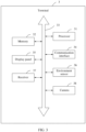
- FIG. 3 is a block diagram of a structure a terminal according to this application.
- the terminal 3 may be a tablet computer, a mobile phone, an e-reader, a notebook computer, a vehicle-mounted device, a wearable device, or the like.
- the terminal 3 may include a processor 31, a memory 32, a communication bus 33, a communication interface 34, a display panel 35, an ambient light sensor 36, a receiver 37, and a camera 38.
- the processor 31 is in a communication connection to the memory 32, the communication interface 34, the display panel 35, the ambient light sensor 36, the receiver 37, and the camera 38 by using the communication bus 33.
- the structure shown in FIG. 3 does not constitute a limitation on the terminal 3, and the terminal 3 may include more or fewer components than those shown in the figure, or combine some components, or split some components, or have different component arrangements.
- the processor 31 may be a central processing unit (Central Processing Unit, CPU), or may be another general-purpose processor, a digital signal processor (Digital Signal Processor, DSP), an application-specific integrated circuit (Application-Specific Integrated Circuit, ASIC), a field-programmable gate array (Field-Programmable Gate Array, FPGA), or another programmable logic device, a discrete gate or a transistor logic device, a discrete hardware component, or the like.
- the processor 31 may be a microprocessor, or the processor 31 may be any conventional processor, or the like.
- the processor 31 is a control center of the terminal 3, and is connected to all parts of the entire terminal 3 by using various interfaces and lines.
- the memory 32 may be configured to store a software program and/or a module/unit.
- the processor 31 implements various functions of the terminal 3 by running or executing the software program and/or the module/unit stored in the memory 32 and invoking data stored in the memory 32.
- the memory 32 may mainly include a program storage area and a data storage area, where the program storage area may store an operating system, an application program required by at least one function (for example, a voice playing function and an image playing function), and the like, and the data storage area may store data (for example, audio data) created according to use of the terminal 3, and the like.
- the memory 32 may include a nonvolatile computer-readable memory, for example, a hard disk, a memory, a plug-in hard disk, a smart media card (Smart Media Card, SMC), a secure digital (Secure Digital, SD) card, a flash card (Flash Card), at least one magnetic disk storage device, a flash memory, or another nonvolatile solid-state storage device.
- a nonvolatile computer-readable memory for example, a hard disk, a memory, a plug-in hard disk, a smart media card (Smart Media Card, SMC), a secure digital (Secure Digital, SD) card, a flash card (Flash Card), at least one magnetic disk storage device, a flash memory, or another nonvolatile solid-state storage device.
- the communication interface 34 may be configured to communicate with another device or a communication network, for example, an Ethernet, a radio access network (radio access network, RAN), or a wireless local area network (wireless local area network, WLAN).
- a radio access network radio access network, RAN
- a wireless local area network wireless local area network, WLAN
- the display panel 35 may be configured to display an image, prompt information, and the like.
- the display panel 35 may be a liquid crystal display (liquid crystal display, LCD), an organic light-emitting diode (organic light-emitting diode, OLED) display, an active-matrix organic light emitting diode (active-matrix organic light emitting diode, AMOLED) display, a flexible light-emitting diode (flexible light-emitting diode, FLED) display, a quantum dot light-emitting diode (quantum dot light emitting diode, QLED) display, or the like.
- LCD liquid crystal display
- OLED organic light-emitting diode
- AMOLED active-matrix organic light emitting diode
- FLED flexible light-emitting diode
- QLED quantum dot light-emitting diode
- the ambient light sensor 36 is configured to sense external ambient light, so that the processor 31 automatically adjusts brightness of the display panel 35 of the terminal 3 based on the sensed external ambient light.
- the receiver 37 is configured to convert an audio electrical signal into a sound signal to implement audio (voice and music) playback.
- the camera 38 is configured to capture an image.
- the camera 38 includes a front-facing camera.
- the camera 38 may further include a rear-facing camera.
- the terminal 3 is a mobile phone. It may be understood that, in this embodiment of this application, the terminal 3 may alternatively be a tablet computer, an e-reader, a notebook computer, a vehicle-mounted device, or a wearable device.
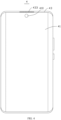
- FIG. 4 is a schematic diagram of a structure of a terminal.
- FIG. 5 is a partial exploded view of a terminal. Appearance shapes in FIG. 4 and FIG. 5 are merely examples of the mobile phone, do not represent an appearance shape and a size of the mobile phone, and do not represent that an internal structure of the mobile phone is unique.
- the terminal 4 includes a cover glass 41, a display panel 42, a middle frame 43, a circuit board 44, a rear cover 45, an ambient light sensor 46, a camera 47, and a receiver 48.
- the display panel 42, the circuit board 44, the ambient light sensor 46, the camera 47, and the receiver 48 are disposed in accommodating space formed by the cover glass 41, the middle frame 43, and the rear cover 45.
- the cover glass 41, the display panel 42, the circuit board 44, and the rear cover 45 are sequentially disposed from top to bottom.
- the cover glass 41 covers the display panel 42.
- a light transmission part 410 is disposed on the cover glass 41.
- the middle frame 43 includes a side frame 431 and a middle plate 432.
- the side frame 431 is disposed around the display panel 42 and the periphery of the circuit board 44.
- a plurality of sound outlet holes 433 are provided at the top of the side frame 431.
- FIG. 4 shows that the sound outlet hole 433 is in an oblique upward direction of the top of the side frame 431.
- this application is not limited to the position shown in FIG.
- the middle plate 432 may alternatively be directly above the top of the side frame 431 or the like.
- a peripheral side of the middle plate 432 is fastened to an inner peripheral side of the side frame 431.
- the middle plate 432 may be integrally formed with the side frame 431.
- the middle plate 432 divides an inner cavity of the terminal into upper and lower parts.
- the display panel 42 is accommodated in the upper part.
- the ambient light sensor 46, the camera 47, the receiver 48, and the circuit board 44 are accommodated in the lower part.
- the middle plate 432 is located on an inner side of the side frame 431, and is located between the display panel 42 and the circuit board 44.
- the ambient light sensor 46 senses external ambient light through at least one sound outlet hole 433.
- the camera 47 collects light by using the light transmission part 410.
- the receiver 48 guides sound to the terminal 4 through the other sound outlet holes 433.
- FIG. 6 is a schematic diagram of partial three-dimensional assembly of a terminal according to Embodiment 1 of this application.
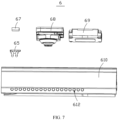
- FIG. 7 is an exploded schematic diagram of a top area of a terminal.
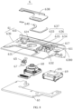
- FIG. 8 is an exploded schematic diagram of a terminal from a first angle of view.
- FIG. 9 is an exploded schematic diagram of a terminal from a second angle of view.
- the terminal 6 includes a circuit board 60, a middle frame 61, a light guide 65, an ambient light sensor 67, a camera 68, and a receiver 69.
- the middle frame 61 includes a side frame 610 and a middle plate 630. An inner peripheral side 611 of the side frame 610 is fastened to a peripheral side 6300 of the middle plate 630.
- the side frame 610 may be integrally formed with the middle plate 630.
- the side frame 610 is disposed around the circuit board 60.
- a row of sound outlet holes 612 are provided at the top of the side frame 610.
- the sound outlet hole 612 penetrates through the side frame 610.
- the sound outlet hole 612 is slender and has a small aperture.
- the aperture of the sound outlet hole 612 may be within 1 millimeter.
- a hole wall of the sound outlet hole 612 is inclined towards the circuit board 60.
- the sound outlet hole 612 includes a first sound outlet hole 613 and a second sound outlet hole 614.
- the first sound outlet hole 613 is located at the top of the side frame 610 of the terminal, and communicates the inside of the terminal 6 with the outside.
- a part that is of a hole wall 615 (as shown in FIG. 10 ) of the first sound outlet hole 613 and that is close to an inner wall 616 of the side frame 610 and a part that is of a hole wall 617 of the second sound outlet hole 614 and that is close to the inner wall 616 of the side frame 610 are located on two opposite sides of the middle plate 630. Specifically, the part that is of the hole wall 615 of the first sound outlet hole 613 and that is close to the circuit board 60 is located at a first side (as shown in FIG. 9 ) of the middle plate 630. The part that is of the hole wall 617 of the second sound outlet hole 614 and that is close to the circuit board 60 is located at a second side (as shown in FIG.
- the first side and the second side are opposite sides. In this embodiment, the first side is located below, and the second side is located above.
- the first sound outlet hole 613 is configured to allow external ambient light to enter the inside of the terminal 6, and the second sound outlet hole 614 is configured to transmit sound inside the terminal 6 to the outside, so that a user can answer the sound.
- a plurality of first sound outlet holes 613 may be provided. In this embodiment, there are two first sound outlet holes 613. Usually, a quantity of first sound outlet holes 613 is not limited to two, or may further be another quantity, for example, three.
- FIG. 10 is a partial enlarged schematic diagram at X in FIG. 9 .
- the side frame 610 forms an annular step 618 in the first sound outlet hole 613.
- the annular step 618 divides the first sound outlet hole 613 into a first part 619 and a second part 620.
- a hole wall 621 of the first part 619 is closer to the circuit board 60 than a hole wall 622 of the second part 620.
- An aperture of the first part 619 is greater than that of the second part 620.
- the annular step 618 also connects the hole wall 621 of the first part 619 to the hole wall 622 of the second part 620 by an abutting surface 623.
- an adhesive layer 624 (as shown in FIG. 9 ) is disposed on the abutting surface 623.
- First parts 619 of a plurality of first sound outlet holes 613 are connected to each other to form a third part 625.
- first parts 619 of two first sound outlet holes 613 are connected to each other to form a third part 625.
- a hole wall 626 of the third part 625 is closer to the inner wall 616 of the side frame 610 than the hole wall 622 of the second part 620.
- the middle plate 630 is located above the circuit board 60.
- a camera through hole 631 and a receiver through hole 632 are formed on the middle plate 630.
- the camera through hole 631 is configured to shelter the camera 68.
- the receiver through hole 632 is configured to shelter the receiver 69.
- the sound outlet 691 of the receiver 69 faces the display panel.
- a first sound guide slot 633 is formed at a joint between the middle plate 630 and the side frame 610.
- the first sound guide slot 633 communicates with the second sound outlet hole 614.
- the first sound guide slot 633 is formed at the joint between the middle plate 630 and the side frame 610.
- the first sound guide slot 633 communicates with the second sound outlet hole 614.
- the middle plate 630 is recessed at the receiver through hole 632 to form a support plate 634 and a limiting surface 635.
- the support plate 634 and the limiting surface 635 form a second sound guide slot 636.
- the second sound guide slot 636 communicates with the receiver through hole 632, and communicates with the first sound guide slot 633.
- the second sound guide slot 636 and the first sound guide slot 633 form a sound guide slot 637.
- the terminal 6 further includes a sound cavity cover 638.
- a shape of the sound cavity cover 638 matches a shape of the sound guide slot 637.
- the sound cavity cover 638 covers the sound guide slot 637 to form a sealed sound cavity 639.
- the sound cavity 639 is disposed inside the terminal.
- the terminal 6 further includes sealant 640, and the sealant 640 is disposed on an edge of a surface that is of the sound cavity cover 638 and that faces the middle plate 630, so that the sound cavity cover 638 is in a sealed connection to the middle plate 630. Therefore, sealing of the sound cavity 639 can be improved.
- the sound cavity 639 communicates with the second sound outlet hole 614, communicates with the receiver through hole 632, and is isolated from the first sound outlet hole 613.
- the sound outlet 691 of the receiver 69 communicates with the sound cavity 639, so that the sound cavity 639 may be configured to transmit, to the outside by using the second sound outlet hole 614, sound emitted by the sound outlet 691 of the receiver 69.
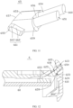
- FIG. 11 is a schematic diagram of a light guide according to Embodiment 1 of a terminal.
- FIG. 12 is a first cross-sectional schematic diagram of Embodiment 1 of a terminal.
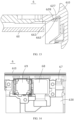
- FIG. 13 is a second cross-sectional schematic diagram of Embodiment 1 of a terminal.
- a light guide 65 may be disposed in the first sound outlet hole 613.
- the light guide 65 enables the external ambient light to be evenly transmitted inside the light guide 65, thereby reducing a scattering loss of the external ambient light inside the first sound outlet hole 613, and increasing detection sensitivity of the external ambient light.
- the light guide 65 is mounted in two first sound outlet holes 613.
- the light guide 65 includes a light incident surface 651 and a light emergent surface 652 (as shown in FIG. 9 ).
- the light guide 65 is configured to directly emit the external ambient light from the light incident surface 651 to the light emergent surface 652.
- the light guide 65 includes a light guide body 653, a plurality of light pipes 654, and a mounting part 655.
- a cross section of the light guide body 653 is generally oval.
- the light guide body 653 includes a first end face 656 and a second end face 657 opposite to the first end face 656.
- An end part in which the second end face 657 of the light guide body 653 is located includes a bottom surface 658 (as shown in FIG. 9 ).
- the bottom surface 658 is planar.
- the light guide body 653 is accommodated in the third part 625.
- a quantity of light pipes 654 matches a quantity of first sound outlet holes 613, and is two. Each light pipe 654 extends from the first end face 656 of the light guide body 653 in a direction away from the light guide body 653.
- the first end face 656 forms a step surface 659 at a joint between the light guide body 653 and the light pipe 654.
- an aperture of the first sound outlet hole 613 is relatively small, so that a length-to-diameter ratio of the first sound outlet hole 613 is relatively large. This imposes a relatively high requirement on strength, and manufacturing and mounting of the light guide 65.
- a diameter of the light guide body 653 is greater than a diameter of the light pipe 654, a size in a diameter direction of the light guide 65 is increased, and strength of the light guide 65 is improved. This facilitates manufacturing and mounting, and reduces scattering of the ambient light in the light guide 65.
- the step surface 659 abuts against the abutting surface 623, and is fastened to the abutting surface 623 by using the adhesive layer 624 (as shown in FIG. 12 ).
- the adhesive layer 624 may be formed by using a double-sided adhesive, and is formed by dispensing glue, or solidified by liquid glue. Therefore, a sealing function of the terminal can be implemented by using the adhesive layer 624, and the light guide 65 can be fastened in the first sound outlet hole 613.
- Each light pipe 654 is accommodated in a second part 620. End faces 660 that are of the light pipes 654 and that are away from the first end face 656 form the light incident surface 651.
- the mounting part 655 is located in the terminal.
- the mounting part 655 extends on a circumferential surface of the end part away from two opposite sides of the bottom surface 658 (as shown in FIG. 9 ) of the light guide body 653. Because the mounting part 655 is widened at the light guide body 653, the light guide 65 is easy to mount.
- a mounting surface 661 that is of the mounting part 655 and that is opposite to the bottom surface 658 (as shown in FIG. 9 ) includes a first mounting surface 662 and a second mounting surface 663.
- the second mounting surface 663 is inclined relative to the first mounting surface 662, to form an included angle greater than 180°.
- the side frame 610 configured to limit the mounting part 655 is recessed at the third part 625 to form a first contact surface 627 and a second contact surface 628.
- the second contact surface 628 is inclined relative to the first contact surface 627, to form an included angle less than 180°.
- the first mounting surface 662 is in contact with the first contact surface 627, and the second mounting surface 663 is in contact with the second contact surface 628 (as shown in FIG. 13 ). Therefore, the light guide 65 may be mounted in the first sound outlet hole 613 by using the mounting part 655.
- the bottom surface 664 (as shown in FIG. 9 ) of the mounting part 655 and the bottom surface 658 (as shown in FIG. 9 ) of the light guide body 653 form a flat plane.
- the plane formed by the bottom surface 664 of the mounting part 655 and the bottom surface 658 of the light guide body 653 is the light emergent surface 652.
- the light emergent surface 652 is a flat plane, and can evenly emit external ambient light.
- the external ambient light is in the light guide 65, does not need to be reflected, and is directly emitted from the light incident surface 651 to the light emergent surface 652 (as shown in FIG. 9 ).
- the mounting part 655 may alternatively be omitted, so that the bottom surface of the light guide body 653 is the light emergent surface 652 (as shown in FIG. 9 ).
- the light emergent surface 652 is not limited to a flat plane, but may alternatively be in another shape, for example, a shape that meets a requirement of the ambient light sensor for detecting an amount of incoming light of the external ambient light, such as a lens shape.
- a shape of the bottom surface 664 of the mounting part 655 and a shape of the bottom surface 658 of the light guide body 653 may not be limited to the above-described shapes, but may alternatively be another shape based on the shape of the light emergent surface 652.
- the ambient light sensor 67 is located on an inner side of the side frame 610, and below the middle plate 630.
- the ambient light sensor 67 is opposite to the light emergent surface 652.
- the ambient light sensor 67 may be disposed on the circuit board 60, or connected to the circuit board 60 by using a flexible circuit board.
- the ambient light sensor 67, the receiver 69, and the camera 68 are in horizontal parallel positions (as shown in FIG. 14 ), and are disposed on the circuit board 60.
- the ambient light sensor 67 senses external ambient light by using the first sound outlet hole 613 and the light guide 65.
- the ambient light sensor 67 since light is reflected on a surface of an object, the ambient light sensor 67 is allowed to have an eccentric distance from main axes of the two first sound outlet holes 613, that is, does not need to face the first sound outlet hole 613.
- a function of the ambient light sensor 67 can be implemented as long as an intensity of light reflected to the ambient light sensor 67 is beyond a sensing range of the ambient light sensor 67.
- the terminal 6 is configured to adjust brightness of the display panel based on the external ambient light sensed by the ambient light sensor 67.
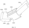
- FIG. 15 is a schematic diagram of a light guide according to Embodiment 2 of a terminal.
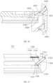
- FIG. 16 is a first cross-sectional schematic diagram of Embodiment 2 of a terminal.
- a structure of the light guide in Embodiment 2 is similar to that of the light guide in Embodiment 1.
- the light guide 150 includes a light guide body 1500, a plurality of light pipes 1501, and a mounting part 1502.
- a third part of a side frame in Embodiment 2 is similar to the third part of the side frame in Embodiment 1, and a third part 1601 is also formed on the side frame.
- a difference lies in a structure of the mounting part 1502 and a structure of a position that limits the mounting part 1502 on the side frame 1600. Details are provided below.
- the mounting part 1502 extends on the second end face 1503 from an edge of the bottom surface 1504 of the light guide body 1500 in a direction away from the light pipe 1501.
- the mounting surface 1506 that is of the mounting part 1502 and that is opposite to the bottom surface 1505 of the mounting part 1502 forms an included angle less than 180° relative to the connected light guide body 1500.
- the side frame 1600 configured to limit the mounting part 1502 forms an inclined surface 1602 at the third part 1601.
- the inclined surface 1602 is inclined relative to a hole wall 1603 of the third part 1601, to form an included angle greater than 180°.
- a circumferential surface of the light guide body 1500 is in contact with the hole wall 1603, and the mounting surface 1506 is in contact with the inclined surface 1602 (as shown in FIG. 16 ). Therefore, the light guide 150 may be mounted in the first sound outlet hole 1604 by using the mounting part 1502.
- FIG. 17 is a schematic cross-sectional diagram of a terminal according to Embodiment 2 of this application.
- a structure of the terminal in Embodiment 2 is similar to that of the terminal in Embodiment 1, and the terminal 170 includes a first sound outlet hole 1701 and a light guide 1702.
- a difference lies in that:
- the light guide 1702 is disposed in the first sound outlet hole 1701.
- the light guide 1702 includes a light incident surface 1703 and a light emergent surface 1704.
- the light guide 1702 includes a light pipe 1705 and a bottom 1706.
- the light pipe 1705 is fastened to the bottom 1706.
- the light pipe 1705 includes a first end face 1707 and a second end face 1708 opposite to the first end face 1707.
- a dashed line is added in the figure to indicate the second end face 1708.
- the dashed line does not limit an obvious boundary at a joint between the light pipe 1705 and the bottom 1706.
- the first end face 1707 is the light incident surface 1703.
- the second end face 1708 is inclined relative to the first end face 1707.
- the bottom 1706 is in a shape of a round table.
- the bottom 1706 includes a first bottom surface 1709 and a second bottom surface 1710.
- a radius of the first bottom surface 1709 is less than a radius of the second bottom surface 1710.
- the first bottom surface 1709 is fastened to the second end face 1708 of the light pipe 1705.
- the second bottom surface 1710 is the light emergent surface 1704.
- the terminal may further have another deformation.
- the first sound outlet hole is located above the middle plate.
- the sound cavity communicates with the first sound outlet hole.
- a light sensitive inlet of the ambient light sensor communicates with the sound cavity.
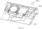
- a light sensitive inlet 1802 is further formed on the middle plate 1801.
- the light sensitive inlet 1802 is the ambient light sensor through hole.
- the light sensitive inlet 1802 is configured to shelter the ambient light sensor 1803, and the ambient light sensor 1803 and the light sensitive inlet 1802 are sealed.
- an aperture of the first sound outlet hole of the terminal is separately increased, or a plurality of first sound outlet holes communicate with each other.
- the ambient light sensor senses external ambient light by using the sound outlet hole, so that a gap between the middle frame and a display panel can be omitted, to reduce appearance black edges of a cover glass, increase a screen-to-body ratio and improve aesthetics of the terminal, and implement a simpler ambient light detection solution.
- the external ambient light is directly detected by using the existing sound outlet hole, without imposing a requirement on light transmission of the display panel and additionally providing an opening. This can reduce costs, avoids impact by the display panel, and causes low optical noise.
- the light guide is disposed in the sound outlet hole, to reduce a scattering loss of the external ambient light.
- a part that is of the first sound outlet hole and that is close to the ambient light sensor and a part that is of the light guide and that is close to the ambient light sensor are widened, so that an incoming light scattering loss can be reduced, and sealing and fastening of the light guide are facilitated.
- the external ambient light is directly emitted from the light incident surface to the light emergent surface, so that a scattering loss of the external ambient light can be further reduced.
- the ambient light sensor is opposite to the light emergent surface, so that a loss of external ambient light incident from the light emergent surface to the ambient light sensor can be avoided.
Landscapes
- Physics & Mathematics (AREA)
- Engineering & Computer Science (AREA)
- Signal Processing (AREA)
- General Physics & Mathematics (AREA)
- Spectroscopy & Molecular Physics (AREA)
- Computer Networks & Wireless Communication (AREA)
- Sustainable Development (AREA)
- Life Sciences & Earth Sciences (AREA)
- Optics & Photonics (AREA)
- Acoustics & Sound (AREA)
- Human Computer Interaction (AREA)
- Arrangement Of Elements, Cooling, Sealing, Or The Like Of Lighting Devices (AREA)
- Telephone Set Structure (AREA)
Applications Claiming Priority (2)
| Application Number | Priority Date | Filing Date | Title |
|---|---|---|---|
| CN202110126416.8A CN112968984B (zh) | 2021-01-29 | 2021-01-29 | 终端 |
| PCT/CN2021/137509 WO2022160976A1 (zh) | 2021-01-29 | 2021-12-13 | 终端 |
Publications (2)
| Publication Number | Publication Date |
|---|---|
| EP4262177A1 true EP4262177A1 (de) | 2023-10-18 |
| EP4262177A4 EP4262177A4 (de) | 2024-06-12 |
Family
ID=76272423
Family Applications (1)
| Application Number | Title | Priority Date | Filing Date |
|---|---|---|---|
| EP21922566.1A Pending EP4262177A4 (de) | 2021-01-29 | 2021-12-13 | Endgerät |
Country Status (3)
| Country | Link |
|---|---|
| EP (1) | EP4262177A4 (de) |
| CN (2) | CN112968984B (de) |
| WO (1) | WO2022160976A1 (de) |
Cited By (1)
| Publication number | Priority date | Publication date | Assignee | Title |
|---|---|---|---|---|
| EP4138370A4 (de) * | 2021-06-29 | 2024-07-31 | Honor Device Co., Ltd. | Endgerätevorrichtung |
Families Citing this family (6)
| Publication number | Priority date | Publication date | Assignee | Title |
|---|---|---|---|---|
| CN112968984B (zh) * | 2021-01-29 | 2022-09-23 | 华为技术有限公司 | 终端 |
| CN113641262B (zh) * | 2021-07-16 | 2023-02-17 | 荣耀终端有限公司 | 电子设备 |
| CN115643325B (zh) * | 2021-07-20 | 2025-10-10 | 北京小米移动软件有限公司 | 一种移动终端 |
| CN118044172A (zh) * | 2021-10-01 | 2024-05-14 | 三星电子株式会社 | 包括通气孔的电子装置 |
| CN119895349A (zh) * | 2022-09-19 | 2025-04-25 | 三星电子株式会社 | 包括声音输出模块的电子装置 |
| CN118329198A (zh) * | 2023-01-12 | 2024-07-12 | 华为技术有限公司 | 环境光感应装置及终端设备 |
Family Cites Families (14)
| Publication number | Priority date | Publication date | Assignee | Title |
|---|---|---|---|---|
| KR20150016454A (ko) * | 2013-08-02 | 2015-02-12 | 에스케이텔레콤 주식회사 | 무선랜 신호를 이용한 측위장치 및 방법 |
| CN204119279U (zh) * | 2014-06-18 | 2015-01-21 | 锤子科技(北京)有限公司 | 一种移动终端 |
| CN206023870U (zh) * | 2016-08-18 | 2017-03-15 | 歌尔股份有限公司 | 一种立体声移动终端 |
| CN106453722A (zh) * | 2016-11-30 | 2017-02-22 | 努比亚技术有限公司 | 一种听筒装置及移动终端 |
| CN206339903U (zh) * | 2016-12-06 | 2017-07-18 | 广东欧珀移动通信有限公司 | 一种面板、传感器组件及移动终端 |
| CN106936954B (zh) * | 2017-03-07 | 2020-05-12 | Oppo广东移动通信有限公司 | 移动终端 |
| KR102373308B1 (ko) * | 2017-04-06 | 2022-03-11 | 삼성전자주식회사 | 적어도 하나의 관통 홀이 형성된 하우징을 포함하는 전자 장치 |
| CN207720411U (zh) * | 2017-09-06 | 2018-08-10 | 维沃移动通信有限公司 | 一种移动终端 |
| CN207530869U (zh) * | 2017-11-06 | 2018-06-22 | 维沃移动通信有限公司 | 一种移动终端 |
| CN108429826B (zh) * | 2018-02-24 | 2020-12-29 | Oppo广东移动通信有限公司 | 电子设备 |
| CN108924279B (zh) * | 2018-06-01 | 2020-09-04 | Oppo广东移动通信有限公司 | 壳体组件以及电子装置 |
| CN112153183B (zh) * | 2019-06-28 | 2022-07-26 | Oppo广东移动通信有限公司 | 移动终端及通信系统 |
| CN111785230B (zh) * | 2020-06-22 | 2022-07-26 | Oppo广东移动通信有限公司 | 一种亮度调节方法及终端、存储介质 |
| CN112968984B (zh) * | 2021-01-29 | 2022-09-23 | 华为技术有限公司 | 终端 |
-
2021
- 2021-01-29 CN CN202110126416.8A patent/CN112968984B/zh active Active
- 2021-01-29 CN CN202211051192.XA patent/CN115567625A/zh active Pending
- 2021-12-13 WO PCT/CN2021/137509 patent/WO2022160976A1/zh not_active Ceased
- 2021-12-13 EP EP21922566.1A patent/EP4262177A4/de active Pending
Cited By (2)
| Publication number | Priority date | Publication date | Assignee | Title |
|---|---|---|---|---|
| EP4138370A4 (de) * | 2021-06-29 | 2024-07-31 | Honor Device Co., Ltd. | Endgerätevorrichtung |
| US12598710B2 (en) | 2021-06-29 | 2026-04-07 | Honor Device Co., Ltd. | Terminal device |
Also Published As
| Publication number | Publication date |
|---|---|
| EP4262177A4 (de) | 2024-06-12 |
| CN112968984B (zh) | 2022-09-23 |
| WO2022160976A1 (zh) | 2022-08-04 |
| CN115567625A (zh) | 2023-01-03 |
| CN112968984A (zh) | 2021-06-15 |
Similar Documents
| Publication | Publication Date | Title |
|---|---|---|
| EP4262177A1 (de) | Endgerät | |
| US10764414B2 (en) | Display screen component and electronic device | |
| USRE50466E1 (en) | Display device and mobile information terminal including the same | |
| EP3522504B1 (de) | Endgeräteanzeigeanordnung und mobiles endgerät | |
| US11609446B2 (en) | Electronic device and middle frame thereof | |
| CN207853957U (zh) | 终端显示屏组件及移动终端 | |
| JP7228713B2 (ja) | モバイル端末及びミドルフレーム | |
| US11281255B2 (en) | Electronic device having waterproof structure for electronic component | |
| CN207853958U (zh) | 终端显示屏组件及移动终端 | |
| JP7241896B2 (ja) | 電子機器、表示画面アセンブリ及びカバープレート | |
| US12235508B2 (en) | Electronic device including camera module | |
| CN107945660A (zh) | 显示屏组件及电子设备 | |
| CN108566460B (zh) | 显示屏组件及电子设备 | |
| CN107945767A (zh) | 显示屏组件及电子设备 | |
| RU2771517C2 (ru) | Электронное устройство | |
| CN111371926A (zh) | 显示屏组件及电子设备 | |
| CN107911507A (zh) | 显示屏组件及电子设备 | |
| WO2019141060A1 (zh) | 移动终端 | |
| US20230263004A1 (en) | Electronic Devices Having Curved Displays With Supporting Frames | |
| CN107818733B (zh) | 显示屏组件及电子设备 | |
| US11750728B2 (en) | Mobile terminal and electronic device | |
| US20200220959A1 (en) | Display assembly and electronic device including the same | |
| US11588086B2 (en) | Micro-LED display | |
| CN107948421A (zh) | 显示屏及电子设备 | |
| US20250004257A1 (en) | Lens device and electronic device |
Legal Events
| Date | Code | Title | Description |
|---|---|---|---|
| STAA | Information on the status of an ep patent application or granted ep patent |
Free format text: STATUS: THE INTERNATIONAL PUBLICATION HAS BEEN MADE |
|
| PUAI | Public reference made under article 153(3) epc to a published international application that has entered the european phase |
Free format text: ORIGINAL CODE: 0009012 |
|
| STAA | Information on the status of an ep patent application or granted ep patent |
Free format text: STATUS: REQUEST FOR EXAMINATION WAS MADE |
|
| 17P | Request for examination filed |
Effective date: 20230714 |
|
| AK | Designated contracting states |
Kind code of ref document: A1 Designated state(s): AL AT BE BG CH CY CZ DE DK EE ES FI FR GB GR HR HU IE IS IT LI LT LU LV MC MK MT NL NO PL PT RO RS SE SI SK SM TR |
|
| DAV | Request for validation of the european patent (deleted) | ||
| DAX | Request for extension of the european patent (deleted) | ||
| A4 | Supplementary search report drawn up and despatched |
Effective date: 20240513 |
|
| RIC1 | Information provided on ipc code assigned before grant |
Ipc: H04M 1/22 20060101ALN20240506BHEP Ipc: H04W 52/02 20090101ALI20240506BHEP Ipc: F21V 8/00 20060101ALI20240506BHEP Ipc: G01J 1/42 20060101ALI20240506BHEP Ipc: G01J 1/04 20060101ALI20240506BHEP Ipc: G01J 1/02 20060101ALI20240506BHEP Ipc: H04M 1/03 20060101ALI20240506BHEP Ipc: H04M 1/02 20060101AFI20240506BHEP |
|
| STAA | Information on the status of an ep patent application or granted ep patent |
Free format text: STATUS: EXAMINATION IS IN PROGRESS |
|
| 17Q | First examination report despatched |
Effective date: 20250917 |