EP4262307A1 - Procédé et appareil de transmission de canal pusch, et dispositif et support de stockage - Google Patents
Procédé et appareil de transmission de canal pusch, et dispositif et support de stockage Download PDFInfo
- Publication number
- EP4262307A1 EP4262307A1 EP22739146.3A EP22739146A EP4262307A1 EP 4262307 A1 EP4262307 A1 EP 4262307A1 EP 22739146 A EP22739146 A EP 22739146A EP 4262307 A1 EP4262307 A1 EP 4262307A1
- Authority
- EP
- European Patent Office
- Prior art keywords
- srs resource
- indication information
- ptrs
- value
- port
- Prior art date
- Legal status (The legal status is an assumption and is not a legal conclusion. Google has not performed a legal analysis and makes no representation as to the accuracy of the status listed.)
- Pending
Links
Images

Classifications
-
- H—ELECTRICITY
- H04—ELECTRIC COMMUNICATION TECHNIQUE
- H04W—WIRELESS COMMUNICATION NETWORKS
- H04W72/00—Local resource management
- H04W72/12—Wireless traffic scheduling
- H04W72/1263—Mapping of traffic onto schedule, e.g. scheduled allocation or multiplexing of flows
- H04W72/1268—Mapping of traffic onto schedule, e.g. scheduled allocation or multiplexing of flows of uplink data flows
-
- H—ELECTRICITY
- H04—ELECTRIC COMMUNICATION TECHNIQUE
- H04B—TRANSMISSION
- H04B7/00—Radio transmission systems, i.e. using radiation field
- H04B7/02—Diversity systems; Multi-antenna system, i.e. transmission or reception using multiple antennas
- H04B7/04—Diversity systems; Multi-antenna system, i.e. transmission or reception using multiple antennas using two or more spaced independent antennas
- H04B7/06—Diversity systems; Multi-antenna system, i.e. transmission or reception using multiple antennas using two or more spaced independent antennas at the transmitting station
- H04B7/0613—Diversity systems; Multi-antenna system, i.e. transmission or reception using multiple antennas using two or more spaced independent antennas at the transmitting station using simultaneous transmission
- H04B7/0615—Diversity systems; Multi-antenna system, i.e. transmission or reception using multiple antennas using two or more spaced independent antennas at the transmitting station using simultaneous transmission of weighted versions of same signal
- H04B7/0619—Diversity systems; Multi-antenna system, i.e. transmission or reception using multiple antennas using two or more spaced independent antennas at the transmitting station using simultaneous transmission of weighted versions of same signal using feedback from receiving side
- H04B7/0636—Feedback format
- H04B7/0639—Using selective indices, e.g. of a codebook, e.g. pre-distortion matrix index [PMI] or for beam selection
-
- H—ELECTRICITY
- H04—ELECTRIC COMMUNICATION TECHNIQUE
- H04W—WIRELESS COMMUNICATION NETWORKS
- H04W72/00—Local resource management
- H04W72/20—Control channels or signalling for resource management
- H04W72/23—Control channels or signalling for resource management in the downlink direction of a wireless link, i.e. towards a terminal
-
- H—ELECTRICITY
- H04—ELECTRIC COMMUNICATION TECHNIQUE
- H04B—TRANSMISSION
- H04B7/00—Radio transmission systems, i.e. using radiation field
- H04B7/02—Diversity systems; Multi-antenna system, i.e. transmission or reception using multiple antennas
- H04B7/04—Diversity systems; Multi-antenna system, i.e. transmission or reception using multiple antennas using two or more spaced independent antennas
- H04B7/0413—MIMO systems
- H04B7/0456—Selection of precoding matrices or codebooks, e.g. using matrices antenna weighting
-
- H—ELECTRICITY
- H04—ELECTRIC COMMUNICATION TECHNIQUE
- H04L—TRANSMISSION OF DIGITAL INFORMATION, e.g. TELEGRAPHIC COMMUNICATION
- H04L5/00—Arrangements affording multiple use of the transmission path
- H04L5/0001—Arrangements for dividing the transmission path
- H04L5/0014—Three-dimensional division
- H04L5/0023—Time-frequency-space
-
- H—ELECTRICITY
- H04—ELECTRIC COMMUNICATION TECHNIQUE
- H04L—TRANSMISSION OF DIGITAL INFORMATION, e.g. TELEGRAPHIC COMMUNICATION
- H04L5/00—Arrangements affording multiple use of the transmission path
- H04L5/003—Arrangements for allocating sub-channels of the transmission path
- H04L5/0044—Allocation of payload; Allocation of data channels, e.g. PDSCH or PUSCH
-
- H—ELECTRICITY
- H04—ELECTRIC COMMUNICATION TECHNIQUE
- H04L—TRANSMISSION OF DIGITAL INFORMATION, e.g. TELEGRAPHIC COMMUNICATION
- H04L5/00—Arrangements affording multiple use of the transmission path
- H04L5/003—Arrangements for allocating sub-channels of the transmission path
- H04L5/0048—Allocation of pilot signals, i.e. of signals known to the receiver
- H04L5/0051—Allocation of pilot signals, i.e. of signals known to the receiver of dedicated pilots, i.e. pilots destined for a single user or terminal
-
- H—ELECTRICITY
- H04—ELECTRIC COMMUNICATION TECHNIQUE
- H04L—TRANSMISSION OF DIGITAL INFORMATION, e.g. TELEGRAPHIC COMMUNICATION
- H04L5/00—Arrangements affording multiple use of the transmission path
- H04L5/0091—Signalling for the administration of the divided path, e.g. signalling of configuration information
- H04L5/0094—Indication of how sub-channels of the path are allocated
-
- H—ELECTRICITY
- H04—ELECTRIC COMMUNICATION TECHNIQUE
- H04W—WIRELESS COMMUNICATION NETWORKS
- H04W72/00—Local resource management
- H04W72/20—Control channels or signalling for resource management
- H04W72/23—Control channels or signalling for resource management in the downlink direction of a wireless link, i.e. towards a terminal
- H04W72/232—Control channels or signalling for resource management in the downlink direction of a wireless link, i.e. towards a terminal the control data signalling from the physical layer, e.g. DCI signalling
-
- H—ELECTRICITY
- H04—ELECTRIC COMMUNICATION TECHNIQUE
- H04L—TRANSMISSION OF DIGITAL INFORMATION, e.g. TELEGRAPHIC COMMUNICATION
- H04L5/00—Arrangements affording multiple use of the transmission path
- H04L5/003—Arrangements for allocating sub-channels of the transmission path
- H04L5/0053—Allocation of signalling, i.e. of overhead other than pilot signals
Definitions
- This application pertains to the field of communications technologies, and specifically relates to a PUSCH transmission method and apparatus, a device, and a storage medium.
- Physical Uplink shared channel Physical Uplink Shared Channel, PUSCH
- transmission may use at least one spatial relation and at least one transmitted precoding matrix indicator (Transmitted Precoding Matrix Indicator, TPMI).
- TPMI Transmitted Precoding Matrix Indicator
- a maximum of two spatial relations are used to support PUSCH repetition, and two sets of parameters are also required for corresponding TPMIs.
- a maximum of two SRS resource sets may be configured for codebook-based or non-codebook-based transmission.
- DCI Downlink Control Information
- Embodiments of this application aim to provide a PUSCH transmission method and apparatus, a device, and a storage medium, so as to reduce DCI overheads in an MTRP scenario.
- a PUSCH transmission method includes:
- a PUSCH transmission method includes:
- a PUSCH transmission apparatus includes:
- a PUSCH transmission apparatus includes:
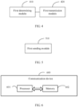
- a terminal device includes a processor, a memory, and a program or instructions stored in the memory and capable of running on the processor, and when the program or the instructions are executed by the processor, the steps of the method according to the first aspect are implemented.
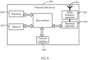
- a network-side device includes a processor, a memory, and a program or instructions stored in the memory and capable of running on the processor, and when the program or the instructions are executed by the processor, the steps of the method according to the second aspect are implemented.
- a readable storage medium where a program or instructions are stored in the readable storage medium, and when the program or the instructions are executed by a processor, the steps of the method according to the first aspect are implemented, or the steps of the method according to the second aspect are implemented.
- a chip includes a processor and a communications interface, the communications interface is coupled to the processor, and the processor is configured to run a program or instructions on the device to implement the method according to the first aspect or the method according to the second aspect.
- the target transmission resource configuration for PUSCH transmission is indicated to the terminal by using at least one of the SRS resource indication information, the TPMI indication information, and the PTRS transmit port indication information, so as to reduce bit overheads for the SRI field and/or TPMI field for the PUSCH transmission resource configuration.
- first and second are intended to distinguish between similar objects but do not necessarily indicate a specific order or sequence. It should be understood that the data used in this way is interchangeable in appropriate circumstances so that the embodiments of this application can be implemented in other orders than the order illustrated or described herein, and “first” and “second” are usually for distinguishing same-type objects but not limiting the number of objects, for example, there may be one or more first objects.
- first and second are usually for distinguishing same-type objects but not limiting the number of objects, for example, there may be one or more first objects.
- “and/or” represents presence of at least one of connected objects, and the symbol “/" in this specification usually indicates an "or” relationship between associated objects.
- LTE Long Term Evolution
- LTE-Advanced LTE-Advanced
- LTE-A LTE-Advanced
- CDMA code division multiple access
- TDMA time division multiple access
- FDMA frequency division multiple access
- OFDMA Orthogonal Frequency Division Multiple Access
- SC-FDMA single-carrier Frequency-Division Multiple Access
- system and “network” in the embodiments of this application are usually used interchangeably. Techniques described herein may be used in the aforementioned systems and radio technologies, and may also be used in other systems and radio technologies.
- New Radio New Radio
- NR New Radio
- NR terms are used in most of the following descriptions, although these technologies may also be applied to other applications than an NR system application, for example, the 6 th generation (6 th Generation, 6G) communications system.
- FIG 1 is a block diagram of a wireless communications system to which the embodiments of this application are applicable.
- the wireless communications system includes a terminal 11 and a network-side device 12.
- the terminal 11 may also be referred to as a terminal device or user equipment (User Equipment, UE), and the terminal 11 may be a terminal-side device, such as a mobile phone, a tablet computer (Tablet Personal Computer), a laptop computer (Laptop Computer) or a notebook computer, a personal digital assistant (Personal Digital Assistant, PDA), a palmtop computer, a netbook, an ultra-mobile personal computer (ultra-mobile personal computer, UMPC), a mobile Internet device (Mobile Internet Device, MID), a wearable device (Wearable Device) or vehicle user equipment (VLTE), or pedestrian user equipment (PUE).
- a terminal device or user equipment User Equipment
- PDA Personal Digital Assistant
- the wearable device includes: a wrist band, earphones, glasses, or the like. It should be noted that a specific type of the terminal 11 is not limited in the embodiments of this application.
- the network-side device 12 may be a base station or a core network.
- the base station may be referred to as a NodeB, an evolved NodeB, an access point, a base transceiver station (Base Transceiver Station, BTS), a radio base station, a radio transceiver, a basic service set (Basic Service Set, BSS), an extended service set (Extended Service Set, ESS), a NodeB, an evolved NodeB (eNB), a home NodeB, a home evolved NodeB, a WLAN access point, a Wi-Fi node, a transmission and reception Point (Transmitting Receiving Point, TRP), or another appropriate term in the art.
- the base station is not limited to a specific technical term. It should be noted that in the embodiments of this application, the base station in the NR system is merely used as an example, and a specific type of the base station is not limited.
- the UE can receive same or different data from multiple TRPs.
- the UE can send different data to multiple TRPs.
- the network side may associate multiple CORESETs configured by the UE with different RRC parameters CORESETPoolIndex, corresponding to different TRPs.
- Each TRP schedules its own uplink transmission PUSCH by sending its own DCI, that is, in the multi-TRP scenario, PUSCH transmission is scheduled by using multi-DCI.
- the communication system further performs PUSCH enhancement under the MTRP, and the UE may send same data to two TRPs.
- one transport block (Transport Block, TB) of PUSCH can be repeatedly sent to multiple TRPs.
- PUSCH repetition uses multiple sets of parameters for different TRPs, including spatial relation, precoding matrix, power control, and the like.
- a maximum of two spatial relations are used to support PUSCH repetition, and two sets of parameters are required for corresponding TPMIs.
- a maximum of two SRS resource sets may be configured for codebook-based or non-codebook-based transmission. For a corresponding SRI field and TPMI field in DCI for scheduling PUSCH, the number of bits needs to be doubled on the original basis to indicate corresponding two sets of parameters.
- a maximum of four SRS resources can be configured in each SRS resource set, and multiple TPMIs for indicating full power transmission codebooks can also be introduced.
- bit overheads for the SRI field and the TPMI field are very large. If the existing solution continues to be used, bit overheads for the SRI field and the TPMI field are directly doubled and become extremely large.
- PUSCH repetition oriented to more TRPs may be supported, and therefore the existing solution is no longer applicable in this case.
- this application provides a PUSCH transmission method and apparatus.
- FIG 2 is a first schematic flowchart of a PUSCH transmission method according to an embodiment of this application. As shown in FIG 2 , the method includes the following steps.
- Step 200 A terminal determines, based on first indication information that is received, a target transmission resource configuration indicated by the first indication information from at least one transmission resource configuration.
- Step 210 Perform PUSCH transmission based on the target transmission resource configuration.
- the first indication information includes at least one of the following:
- the at least one transmission resource configuration is determined based on at least one of the following:
- the target transmission resource configuration may be a resource configuration used for PUSCH transmission by the terminal.
- the network side may configure, for the UE, an SRS resource set to be obtained based on uplink transmission CSI, and each SRS resource set may include two SRS resources.
- the number of ports included in the two SRS resources may be the same, which may be ports 1, 2, and 4.
- the two SRS resources may be configured to correspond to different beams.
- the network side may obtain uplink channel information by measuring SRSs on different SRS resources, select a spatial relation, precoding matrix, power control, MCS, and other parameters for the UE based on the uplink channel information, and indicate the transmission parameters to the UE by using an SRI field/TPMI field/TPC field/MCS field in DCI format0_1/0_2 for PUSCH scheduling.
- SRI field/TPMI field/TPC field/MCS field in DCI format0_1/0_2 for PUSCH scheduling.
- a spatial relation and port same as those of an SRS resource indicated by the SRI field can be used for PUSCH transmission.
- each SRS resource set for non-codebook-based transmission may be configured in each SRS resource set for non-codebook-based transmission, and the number of ports for all SRS resources may be 1.
- An associated CSI-RS can be configured for each SRS resource set and is used for downlink channel measurement by the UE.
- the UE may assume a downlink channel under measurement as an uplink channel, and may calculate a precoding matrix for uplink transmission based on the channel information and use the precoding matrix to precode SRS and send the precoded SRS to the network side.
- the network side may determine precoding used for PUSCH transmission by the UE, and performs indication by using the SRI field in the DCI for PUSCH scheduling. That is, the SRI field may indicate a subset of all precoded SRS resources sent by the UE to indicate a precoding matrix to be used for PUSCH transmission.
- the SRS resource indication information may be used to indicate an SRS resource, and the terminal may perform PUSCH transmission using a spatial relation and port same as those of the SRS resource.
- the TPMI indication information may be used to indicate a precoding matrix, and the terminal may use the precoding matrix to precode the SRS.
- the PTRS transmit port indication information may be used to indicate a PTRS transmit port, and the PTRS-DMRS association field indicates at which layer the PTRS is uploaded.
- the terminal can determine at which layer the PTRS is uploaded.
- one layer may correspond to one DM-RS port.
- any one or a combination of the TPMI indication information, the PTRS transmit port indication information, and the TPMI indication information may be used to indicate corresponding information in a resource configuration for PUSCH transmission.
- PUSCH transmission may be performed based on the resource configuration for PUSCH transmission.
- the terminal may determine, based on the first indication information in the DCI, the target transmission resource configuration indicated by the first indication information.
- the first indication information is used to indicate a target transmission resource configuration in at least one transmission resource configuration.
- the network side may add the first indication information to the DCI and send it to the terminal.
- the terminal may obtain the first indication information and determine the target transmission resource configuration indicated by the first indication information.
- the first indication information includes only indication content, and specific content of the transmission resource configuration may be sent to the terminal by the network side, or be predefined by the protocol, or pre-configured, or indicated by the RRC layer, or indicated by the MAC layer.
- PUSCH transmission may use at least one spatial relation and at least one TPMI.
- multiple spatial relations and multiple sets of TPMI parameters can be proposed, that is, one or more transmission resource configurations may be proposed.
- corresponding resource indication may alternatively be performed by using multiple indication methods. In this way, it can be ensured that PUSCH oriented to multi-TRP transmission is supported on the basis of low overheads for the DCI for scheduling PUSCH transmission.
- the terminal may determine, based on the first indication information, the target transmission resource configuration indicated by the first indication information from one or more transmission resource configurations.
- At least one transmission resource configuration is indicated for PUSCH repetition of the UE. This also ensures that no additional DCI overheads are added.
- the target transmission resource configuration for PUSCH transmission is indicated to the terminal by using at least one of the SRS resource indication information, the TPMI indication information, and the PTRS transmit port indication information, so as to reduce bit overheads for the SRI field and/or TPMI field for the PUSCH transmission resource configuration.
- the SRS resource indication information includes a codepoint value in an SRI field.
- the determining, by the terminal based on the first indication information in the DCI, the target transmission resource configuration indicated by the first indication information includes: based on the codepoint value in the SRI field of the DCI, determining target SRI field codepoint information in at least one piece of SRI field codepoint information; where the at least one piece of SRI field codepoint information is determined by the terminal based on at least one of the following:
- the SRI field codepoint information is associated with at least one SRS resource (SRS resource), or the SRI field codepoint information is associated with at least one SRS resource group (SRS resource group).
- the SRS resource indication information includes a codepoint value in the SRI field, which may be a low-bit value.
- At least one transmission resource configuration may include at least one piece of SRI field codepoint information.
- the SRI field codepoint information is associated with at least one SRS resource (SRS resource).
- SRS resource SRS resource
- the SRI field codepoint information is associated with at least one SRS resource group (SRS resource group).
- SRS resource group SRS resource group
- the terminal may determine, based on the codepoint value in the SRI field, the target SRI field codepoint information indicated by the codepoint value in the SRI field from the at least one piece of SRI field codepoint information, and then obtains an SRS resource or SRS resource group associated with the target SRI field codepoint information.
- different codepoint values in the SRI field are in one-to-one correspondence to the at least one piece of SRI field codepoint information; and a correspondence between the different codepoint values in the SRI field and the at least one piece of SRI field codepoint information is pre-indicated by a network side, pre-defined by a protocol, pre-configured, or indicated by second signaling, where the second signaling is RRC layer signaling or MAC layer signaling.
- different codepoint values of the SRI field may be in one-to-one correspondence to the at least one piece of SRI field codepoint information, and then the terminal may determine, based on the codepoint value in the SRI field, the target SRI field codepoint information in one-to-one correspondence to the codepoint value in the at least one SRI field.
- a correspondence between different codepoint values of the SRI field and the at least one piece of SRI field codepoint information may be pre-indicated by the network side, or pre-defined by the protocol, or pre-configured, or indicated by second signaling, where the second signaling is RRC layer signaling or MAC layer signaling.
- the correspondence between the different codepoint values of the SRI field and the at least one piece of SRI field codepoint information may be described using a table.
- the network side configures two SRS resource sets for non-codebook-based transmission for the UE, and configures four SRS resources (with indexes of 0, 1, 2, and 3) in each resource set, and the UE receives higher-layer signaling MAC CE from the network side, including 4 codepoints.
- the SRI field of the DCI is 2 bits, corresponding to 4 codepoints.
- Table 1 Indication table for SRI field codepoint information Codepoint value in the SRI field SRI field codepoint information 0 1 st SRS resource in a first SRS resource set; 1 1 st SRS resource in a first SRS resource set, and 1 st SRS resource in a second SRS resource set; 2 2 nd SRS resource in a first SRS resource set, and 1 st SRS resource in a second SRS resource set; 3 2 nd SRS resource in a second SRS resource set.
- the codepoint value in the SRI field of the DCI for scheduling PUSCH repetition is 1, it means that the PUSCH repetition corresponds to two spatial relations, a first spatial relation is the same as that of the 1 st SRS resource in the first SRS resource set, and a second spatial relation is the same as that of the 1 st SRS resource in the second SRS resource set.
- the 1 st and 2 nd repetition occasions of the PUSCH repetition use the first spatial relation for transmission, and the 3 rd and 4 th repetition occasions use the second spatial relation for transmission.
- the codepoint value in the SRI field of the DCI for scheduling PUSCH repetition is 2, it means that the PUSCH repetition corresponds to two spatial relations, a first spatial relation is the same as that of the 2 nd SRS resource in the first SRS resource set, and a second spatial relation is the same as that of the 1 st SRS resource in the second SRS resource set.
- the 1 st and 2 nd repetition occasions of the PUSCH repetition use the first spatial relation for transmission, and the 3 rd and 4 th repetition occasions use the second spatial relation for transmission.
- the codepoint value in the SRI field of the DCI for scheduling PUSCH repetition is 3, it means that the PUSCH repetition corresponds to one spatial relation, indicating that a spatial relation same as that of the 2 nd SRS resource in the second SRS resource set is used for all repetition occasions of the PUSCH.
- the network side configures two SRS resource sets for codebook-based transmission for the UE, and configures two SRS resources in each resource set, and the UE receives higher-layer signaling MAC CE from the network side, including four pieces of SRI field codepoint information.
- the SRI field of the DCI is 2 bits, which may be 00, 01, 10, or 11, corresponding to four codepoint values of the SRI field.
- Table 1 Indication table for SRI field codepoint information Codepoint value in the SRI field SRI field codepoint information 0 1 st SRS resource in a first SRS resource set; 1 1 st SRS resource in the first SRS resource set, and 1 st SRS resource in a second SRS resource set; 2 2 nd SRS resource in the first SRS resource set, and 1 st SRS resource in the second SRS resource set; 3 2 nd SRS resource in the second SRS resource set.
- the network side configures two SRS resource sets for non-codebook-based transmission for the UE, and configures four SRS resources (with indexes of 0, 1, 2, and 3) in each resource set, and the UE receives higher-layer signaling MAC CE from the network side, including four pieces of SRI field codepoint information.
- the SRI field of the DCI is 2 bits, which may be 00, 01, 10, or 11, corresponding to four codepoint values of the SRI field.
- Table 2 Indication table for SRI field codepoint information Codepoint value in the SRI field SRI field codepoint information 0 First SRS resource group (SRS resources 0, 1, and 2 in the first SRS resource set); second SRS resource group (SRS resources 1, 2, and 3 in the second SRS resource set); 1 First SRS resource group (SRS resources 1 and 2 in the first SRS resource set); second SRS resource group (SRS resources 2 and 3 in the second SRS resource set); 2 SRS resources 0, 1, 2, and 3 in the first SRS resource set; 3 SRS resources 0, 1, 2, and 3 in the second SRS resource set.
- the codepoint value in the SRI field of the DCI for scheduling PUSCH repetition when the codepoint value in the SRI field of the DCI for scheduling PUSCH repetition is 0, it may indicate that the PUSCH repetition corresponds to two SRS resource groups, and the PUSCH transmission occasions are associated with the two SRS resource groups respectively. Ports corresponding to PUSCH transmission occasions associated with the first SRS resource group are the same as those of the SRS resources with indexes of 0, 1, and 2 in the first SRS resource set. Ports corresponding to PUSCH transmission occasions associated with the second SRS resource group are the same as those of the SRS resources with indexes of 1, 2, and 3 in the first SRS resource set.
- the codepoint value in the SRI field of the DCI for scheduling PUSCH repetition is 0, it indicates that the PUSCH repetition corresponds to two SRS resource groups, and the PUSCH transmission occasions are associated with the two SRS resource groups respectively.
- Ports corresponding to PUSCH transmission occasions associated with the first SRS resource group are the same as those of the SRS resources with indexes of 1 and 2 in the first SRS resource set.
- Ports corresponding to PUSCH transmission occasions associated with the second SRS resource group are the same as those of the SRS resources with indexes of 2 and 3 in the first SRS resource set.
- the codepoint value in the SRI field of the DCI for scheduling PUSCH repetition is 2, it means that the PUSCH repetition is associated with one SRS resource group, and the ports corresponding to all PUSCH transmission occasions are the same as those of SRS resources with indexes of 0, 1, 2, and 3 in the first SRS resource set.
- the codepoint value in the SRI field of the DCI for scheduling PUSCH repetition is 3, it means that the PUSCH repetition is associated with one SRS resource group, and the ports corresponding to all PUSCH transmission occasions are the same as those of SRS resources with indexes of 0, 1, 2, and 3 in the second SRS resource set.
- the network side configures for the UE two SRS resource sets for codebook-based transmission, and two SRS resource sets are configured in each set.
- the UE can receive a MAC CE, and the MAC CE activates one SRS resource in each set. That is, if the number of bits of the SRI field is 0, the SRI codepoint information does not need to be indicated.
- the SRI field of the DCI uses 2 bits to indicate the codepoint value in the SRI field.
- Table 3 Indication table for SRI field codepoint information Codepoint value in the SRI field SRI field codepoint information 0 SRS resource in a first SRS resource set; 1 SRS resource in a second SRS resource set; 2 SRS resource in the first SRS resource set; and SRS resource in the second SRS resource set; 3 SRS resource in the second SRS resource set; and SRS resource in the first SRS resource set.
- the network side configures for the UE two SRS resource sets for codebook-based transmission, and four SRS resource sets are configured in each set.
- the UE receives a MAC CE, and the MAC CE activates two SRS resources in each set.
- the two SRS resources may have the same spatial relation or the same port information, which is alternatively not limited. In this case, there is no need to indicate the SRI field codepoint information.
- the SRI field of the DCI uses 3 bits or 4 bits to indicate the codepoint value in the SRI field.
- Table 4 Indication table for SRI field codepoint information Codepoint value in the SRI field SRI field codepoint information 0 First activated SRS resource in a first SRS resource set; 1 Second activated SRS resource in the first SRS resource set; 2 First activated SRS resource in a second SRS resource set; 3 Second activated SRS resource in the second SRS resource set; 4 First activated SRS resource in the first SRS resource set, and first activated SRS resource in the second SRS resource set; 5 First activated SRS resource in the first SRS resource set, and second activated SRS resource in the second SRS resource set; 6 Second activated SRS resource in the first SRS resource set, and first activated SRS resource in the second SRS resource set; 7 Second activated SRS resource in the first SRS resource set, and second activated SRS resource in the second SRS resource set.
- the number of bits of the SRI filed of the DCI is determined by the number of SRS resource sets. If the number of SRS resource sets is 1, the codepoint value in the SRI field is indicated by 0 bits in the SRI field of the DCI (that is, no indication needs to be performed); if the number of SRS resource sets is 2, the codepoint value in the SRI field is indicated by 2 bits in the SRI field of the DCI.
- Table 5 Indication table for SRI field codepoint information Codepoint value in the SRI field SRI field codepoint information 0 SRS resource in a first SRS resource set; 1 SRS resource in a second SRS resource set; 2 SRS resource in the first SRS resource set; and SRS resource in the second SRS resource set; 3 SRS resource in the second SRS resource set; and SRS resource in the first SRS resource set.
- multiple SRS resources or resource groups associated with the SRI field codepoint information belong to different SRS resource sets (SRS resource sets).
- multiple SRS resources or resource groups associated with the SRI field codepoint information may belong to different SRS resource sets (SRS resource sets).
- one SRS resource set may be configured with only one SRS resource, or two SRS resources, or four SRS resources.
- one SRS resource set may be configured with only one SRS resource group, or two SRS resource groups, or four SRS resource groups.
- the network side or the protocol or the MAC layer or the RRC layer configures multiple SRS resource sets (SRS resource set) for codebook-based transmission for the terminal
- the multiple SRS resources associated with the one piece of SRS field codepoint information come from different SRS resource sets respectively.
- the multiple SRS resource groups associated with the one piece of codepoint information may come from different SRS resource sets respectively.
- the number of SRS resources in all SRS resource groups in each piece of codepoint information may be the same.
- the number of PUSCH transmit ports of the SRS resource associated with one piece of codepoint information is the same.
- SRS resources in each SRS resource group belong to the same SRS resource set.
- the SRS resources in each SRS resource group may come from one SRS resource set.
- the determining, based on the codepoint value in the SRI field of DCI, target SRI field codepoint information in at least one piece of SRI field codepoint information includes:
- the number of bits in the SRI field may be determined based on the number of pieces of the at least one SRI field codepoint information. For example, if the number of pieces of SRI field codepoint information is 5, the number of bits in the SRI field may be at least 3 bits, and a value range of the codepoint value in the SRI field may be 000 to 111, which may be 0 to 7. For example, if the number of pieces of SRI field codepoint information is 4, the number of bits in the SRI field may be at least 2 bits, and the value range of the codepoint value in the SRI field may be 00 to 11, which may be 0 to 4.
- the SRS resource indication information may be determined based on the SRS resource indication information and/or based on the value range of the codepoint value in the SRI field.
- the performing PUSCH transmission based on the target transmission resource configuration includes:
- a corresponding SRS resource may be determined based on the target SRI field codepoint information, that is, to determine an SRS resource associated with the repetition occasion of PUSCH.
- PUSCH transmission may be performed based on the SRS resource associated with the repetition occasion.
- the determining, based on the target transmission resource configuration, an SRS resource associated with a repetition occasion of PUSCH includes:
- a mapping manner between the PUSCH transmission occasions and at least one SRS resource or resource group associated with the target SRI field codepoint information may be determined, and the SRS resource associated with the repetition occasion of the PUSCH is determined based on the mapping manner.
- mapping relationship may be understood as a correspondence formed when at least one SRS resource or resource group is associated with PUSCH transmission occasions one by one.
- one transmission occasion of the PUSCH is associated with one or more SRS resources or SRSs.
- a transmission spatial relation and port corresponding to one transmission occasion of the PUSCH are the same as those of the associated SRS resource or SRS resource group.
- the mapping manner includes: the at least one SRS resource or resource group is alternately or sequentially mapped to a plurality of repetition occasions of PUSCH.
- At least one SRS resource or resource group may be alternately mapped to multiple repetition occasions of the PUSCH.
- the at least one SRS resource or resource group is associated with multiple repetition occasions of the PUSCH one by one.
- the at least one SRS resource or resource group may be alternately mapped to the multiple repetition occasions of the PUSCH by using the following mapping scheme:
- At least one SRS resource or resource group may be sequentially mapped to multiple repetition occasions of the PUSCH.
- the at least one SRS resource or resource group is entirely associated with multiple repetition occasions of the PUSCH one by one.
- the at least one SRS resource or resource group may be sequentially mapped to the multiple repetition occasions of the PUSCH by using the following mapping scheme:
- the mapping manner includes: sequentially performing one-to-one mapping of the at least one SRS resource or resource group to a plurality of partial repetition occasions in one repetition occasion of PUSCH, where the plurality of partial repetition occasions form the one repetition occasion.
- At least one SRS resource or resource group may be sequentially mapped to multiple partial repetition occasions in one repetition occasion of PUSCH one by one.
- the first [N/2] symbols of the PUSCH transmission occasion are associated with the first SRS resource or the first SRS resource group, and the rest N ⁇ ⁇ N / 2 ⁇ symbols are associated with the second SRS resource or the second SRS resource group.
- the first SRS resource/SRS resource group and the second SRS resource/SRS resource group may be determined according to a sequence in the SRI codepoint information, or according to indexes (SRS resource set ID) of the SRS resource sets to which the first SRS resource/SRS resource group and the second SRS resource/SRS resource group belong.
- a sequence of the at least one SRS resource or resource group is determined based on an association sequence in the target SRI field codepoint information.
- a sequence of the at least one SRS resource or resource group may be determined based on an association sequence in the target SRI field codepoint information.
- the first SRS resource/SRS resource group and the second SRS resource/SRS resource group may be determined according to a sequence in the SRI codepoint information.
- a sequence of the at least one SRS resource or resource group is determined based on an index (SRS resource set ID) of an SRS resource set to which the at least one SRS resource or resource group belongs.
- a sequence of the at least one SRS resource or resource group may be determined based on an index (SRS resource set ID) of an SRS resource set to which the at least one SRS resource or resource group belongs.
- the first SRS resource/SRS resource group and the second SRS resource/SRS resource group may be determined according to indexes (SRS resource set ID) of SRS resource sets to which the first resource and second resource or the first resource group and second resource group belong.
- different SRS resource sets are associated with different CORESETPoolIndex; and different DCIs are from CORESETs associated with the different CORESETPoolIndex.
- the SRI fields of different DCIs indicate SRS resources or SRS resource groups from different SRS resource sets.
- different SRS resource sets are associated with different CORESETPoolIndex.
- different DCIs come from CORESETs associated with different CORESETPoolIndex.
- the PTRS transmit port indication information includes indication information in a PTRS-DMRS association field.
- the determining, by the terminal based on the first indication information in the DCI, the target transmission resource configuration indicated by the first indication information includes:
- the DMRS transmit port is associated with an SRS resource or SRS resource group for PUSCH transmission.
- the PTRS transmit port indication information includes the indication information in the PTRS-DMRS association field.
- the indication information in the PTRS-DMRS association field of the DCI may be determined first, and the target association relationship indicated is then determined based on the indication information in the PTRS-DMRS association field from the at least one association relationship between PTRS ports and DMRS transmit ports in the indication information in the PTRS-DMRS association field.
- one layer may correspond to one DMRS transmit port, and it can be determined that the PTRS is uploaded at a layer corresponding to the associated DMRS transmit port.
- the third signaling includes:
- the third signaling may include the maximum number of PTRS ports.
- the third signaling may include the maximum number of transmission ranks and/or SRS ports.
- the indication information in the PTRS-DMRS association field of the DCI may be determined based on the maximum number of PTRS ports and the maximum number of transmission ranks.
- the determining, based on third signaling of an RRC layer or a MAC layer, indication information in a PTRS-DMRS association field of DCI includes:
- the determining, based on third signaling, indication information in a PTRS-DMRS association field of DCI may be determining, based on the third signaling, the number of bits of the indication information in the PTRS-DMRS association field of the DCI, so as to determine a value range of the indication information in the PTRS-DMRS association field of the DCI.
- the number of bits of the indication information in the PTRS-DMRS association field may be 3 bits, and the value range of the indication information in the PTRS-DMRS association field may be 000 to 111, which may be 0 to 7.
- the number of bits of the indication information in the PTRS-DMRS association field may be at least 2 bits, and the value range of the indication information in the PTRS-DMRS association field may be 00 to 11, which may be 0 to 4.
- the determining indication information in a PTRS-DMRS association field of DCI may be determining the indication information in the PTRS-DMRS association field based on the number of bits of the indication information in the PTRS-DMRS association field and/or based on the value range of the indication information in the PTRS-DMRS association field.
- the indication information in the PTRS-DMRS association field includes a second value of the PTRS-DMRS association field; and different second values are in one-to-one correspondence to the at least one association relationship.
- the indication information of the PTRS-DMRS association field may include a second value of the PTRS-DMRS association field, which, for example, may be 0, 1, 2, or 3.
- the determining, based on the indication information in the PTRS-DMRS association field, a target association relationship in at least one association relationship between PTRS ports and DMRS transmit port includes: determining, based on the second value of the PTRS-DMRS association field, that an association relationship corresponding to the second value is the target association relationship.
- an association relationship corresponding to the second value is the target association relationship.
- the value range of the second value is 0 to 3. Then, 0, 1, 2, and 3 are in one-to-one correspondence to four different association relationships. In this way, based on a specific value of the second value, a target association relationship in one-to-one correspondence to the value can be determined.
- the determining, based on the third signaling, the number of bits of the indication information in the PTRS-DMRS association field of the DCI includes: in a case that the maximum number of PTRS ports is 1 or 2 and the maximum number of transmission ranks is 2, determining that the number of bits of the indication information in the PTRS-DMRS association field is 2 bits, so as to further determine the second value of the indication information of the PTRS-DMRS association field.
- the maximum number of PTRS ports is 1 or 2 and the maximum number of transmission ranks is 2, it may be determined that the number of bits of the indication information in the PTRS-DMRS association field is 2 bits.
- the second value of the indication information in the PTRS-DMRS association field includes a third value of the most significant bit MSB and a fourth value of the least significant bit LSB.
- the second value of the indication information in the PTRS-DMRS association field may include a third value of the most significant bit MSB and a fourth value of the least significant bit LSB.
- the third value of the most significant bit MSB includes 0 or 1.
- the target association relationship includes: PTRS port 0 is associated with the 1 st scheduled DM-RS port associated with a first SRS resource or SRS resource group; and in a case that the third value of the most significant bit MSB is 1, the target association relationship includes: PTRS port 0 is associated with the 2 nd scheduled DM-RS port associated with the first SRS resource or SRS resource group.
- the terminal can determine that the target association relationship includes but is not limited to: PTRS port 0 is associated with the 1 st scheduled DM-RS port associated with a first SRS resource or SRS resource group.
- the terminal can determine that the target association relationship includes but is not limited to: PTRS port 0 is associated with the 2 nd scheduled DM-RS port associated with a first SRS resource or SRS resource group.
- the fourth value of the least significant bit LSB includes 0 or 1.
- the target association relationship includes: PTRS port 0 is associated with the 1 st scheduled DM-RS port associated with a second SRS resource or SRS resource group; and in a case that the fourth value of the least significant bit LSB is 1, the target association relationship includes: PTRS port 0 is associated with the 2 nd scheduled DM-RS port associated with the second SRS resource or SRS resource group.
- the terminal can determine that the target association relationship includes but is not limited to: PTRS port 0 is associated with the 1 st scheduled DM-RS port associated with a second SRS resource or SRS resource group.
- the terminal can determine that the target association relationship includes: PTRS port 0 is associated with the 2 nd scheduled DM-RS port associated with a second SRS resource or SRS resource group.
- association relationships may be expressed based on the following table 6.
- Table 6 Target association relationship indication information Second value Target association relationship corresponding to the MSB Target association relationship corresponding to the LSB 0 PTRS port 0 is associated with the 1 st scheduled DM-RS port associated with the first SRS resource or SRS resource group PTRS port 0 is associated with the 1 st scheduled DM-RS port associated with the second SRS resource or SRS resource group 1 PTRS port 0 is associated with the 2 nd scheduled DM-RS port associated with the first SRS resource or SRS resource group PTRS port 0 is associated with the 2 nd scheduled DM-RS port associated with the second SRS resource or SRS resource group
- the PTRS-DMRS association field may be indicated based on 2 bits. That is, as shown the following table, the association relationship may alternatively be expressed based on the following table 7.
- Target association relationship indication information Second value Target association relationship corresponding to the MSB Target association relationship corresponding to the LSB 0 Shared PTRS port 0 or 1 is associated with the 1 st scheduled DM-RS port associated with the first SRS resource or SRS resource group Shared PTRS port 0 or 1 is associated with the 1 st scheduled DM-RS port associated with the second SRS resource or SRS resource group 1 Shared PTRS port 0 or 1 is associated with the 2 nd scheduled DM-RS port associated with the first SRS resource or SRS resource group Shared PTRS port 0 or 1 is associated with the 2 nd scheduled DM-RS port associated with the second SRS resource or SRS resource group
- the determining, based on the indication information in the PTRS-DMRS association field, a target association relationship in at least one association relationship between PTRS ports and DMRS transmit ports includes:
- the terminal can interpret only the MSB or only the LSB.
- the determining, based on the maximum number of transmission ranks and the maximum number of PTRS ports, the number of bits of the indication information in the PTRS-DMRS association field of the DCI includes: in a case that the maximum number of PTRS ports is 1 and the maximum number of transmission ranks is 3 or 4, determine that the number of bits of the indication information in the PTRS-DMRS association field is 4 bits.
- the number of bits of the indication information in the PTRS-DMRS association field is 4 bits.
- the second value of the indication information in the PTRS-DMRS association field includes a fifth value of the most significant bit MSB and a sixth value of the least significant bit LSB; and the most significant bit MSB is 2 bits, and the least significant bit LSB is 2 bits.
- the second value may include a fifth value of the most significant bit MSB and a sixth value of the least significant bit LSB.
- the most significant bit MSB may be the first 2 high-order bits
- the least significant bit LSB may be the last 2 low-order bits.
- the fifth value of the most significant bit MSB is 0, 1, 2, or 3.
- the target association relationship includes: PTRS port 0 is associated with the 1 st scheduled DM-RS port associated with the first SRS resource or SRS resource group;
- the terminal can determine that the target association relationship includes: PTRS port 0 is associated with the 1 st scheduled DM-RS port associated with the first SRS resource or SRS resource group.
- the terminal can determine that the target association relationship includes: PTRS port 0 is associated with the 2 nd scheduled DM-RS port associated with the first SRS resource or SRS resource group.
- the terminal can determine that the target association relationship includes: PTRS port 0 is associated with the 3 rd scheduled DM-RS port associated with the first SRS resource or SRS resource group.
- the terminal can determine that the target association relationship includes: PTRS port 0 is associated with the 4 th scheduled DM-RS port associated with the first SRS resource or SRS resource group.
- the sixth value of the least significant bit LSB is 0, 1, 2, or 3.
- the terminal can determine that the target association relationship includes: PTRS port 0 is associated with the 1 st scheduled DM-RS port associated with the second SRS resource or SRS resource group.
- the terminal can determine that the target association relationship includes: TRS port 0 is associated with the 2 nd scheduled DM-RS port associated with the second SRS resource or SRS resource group.
- the terminal can determine that the target association relationship includes: PTRS port 0 is associated with the 3 rd scheduled DM-RS port associated with the second SRS resource or SRS resource group.
- the terminal can determine that the target association relationship includes: PTRS port 0 is associated with the 4 th scheduled DM-RS port associated with the second SRS resource or SRS resource group.
- association relationships may be expressed based on the following table 7.
- Table 7 Target association relationship indication information Second value Target association relationship corresponding to the MSB Target association relationship corresponding to the LSB 0 PTRS port 0 is associated with the 1 st scheduled DM-RS port associated with the first SRS resource or SRS resource group PTRS port 0 is associated with the 1 st scheduled DM-RS port associated with the second SRS resource or SRS resource group 1 PTRS port 0 is associated with the 2 nd scheduled DM-RS port associated with the first SRS resource or SRS resource group PTRS port 0 is associated with the 2 nd scheduled DM-RS port associated with the second SRS resource or SRS resource group 2 PTRS port 0 is associated with the 3 rd scheduled DM-RS port associated with the first SRS resource or SRS resource group PTRS port 0 is associated with the 3 rd scheduled DM-RS port associated with the second SRS resource or SRS resource group 3 PTRS port 0 is associated with the 4 th
- the determining, based on the indication information in the PTRS-DMRS association field, a target association relationship in at least one association relationship between PTRS ports and DMRS transmit ports includes:
- the terminal can interpret only the MSB.
- the determining, based on the maximum number of transmission ranks and the maximum number of PTRS ports, the number of bits of the indication information in the PTRS-DMRS association field of the DCI includes: in a case that the maximum number of PTRS ports is 2 and the maximum number of transmission ranks is 3 or 4, determining that the number of bits of the indication information in the PTRS-DMRS association field is 4 bits.
- the terminal may determine that the number of bits of the indication information in the PTRS-DMRS association field is 4 bits.
- the second value of the indication information in the PTRS-DMRS association field includes a seventh value of a first bit, an eighth value of a second bit, a ninth value of a third bit, and a tenth value of a fourth bit.
- the second value includes a seventh value of a first bit, an eighth value of a second bit, a ninth value of a third bit, and a tenth value of a fourth bit.
- the seventh value of the first bit includes 0 or 1.
- the target association relationship includes: shared PTRS port 0 is associated with the 1 st scheduled DM-RS port associated with a first SRS resource or SRS resource group; and in a case that the seventh value of the first bit is 1, the target association relationship includes: shared PTRS port 0 is associated with the 2 nd scheduled DM-RS port associated with the first SRS resource or SRS resource group.
- the terminal can determine that the target association relationship includes: shared PTRS port 0 is associated with the 1 st scheduled DM-RS port associated with the first SRS resource or SRS resource group.
- the terminal can determine that the target association relationship includes: shared PTRS port 0 is associated with the 2 nd scheduled DM-RS port associated with the first SRS resource or SRS resource group.
- the eighth value of the second bit includes 0 or 1.
- the target association relationship includes: shared PTRS port 1 is associated with the 1 st scheduled DM-RS port associated with the first SRS resource or SRS resource group; and in a case that the eighth value of the second bit is 1, the target association relationship includes: shared PTRS port 1 is associated with the 2 nd scheduled DM-RS port associated with the first SRS resource or SRS resource group.
- the terminal can determine that the target association relationship includes: shared PTRS port 1 is associated with the 1 st scheduled DM-RS port associated with the first SRS resource or SRS resource group.
- the terminal can determine that the target association relationship includes: shared PTRS port 1 is associated with the 2 nd scheduled DM-RS port associated with the first SRS resource or SRS resource group.
- the ninth value of the third bit includes 0 or 1.
- the target association relationship includes: shared PTRS port 0 is associated with the 1 st scheduled DM-RS port associated with the second SRS resource or SRS resource group; and in a case that the ninth value of the third bit is 1, the target association relationship includes: shared PTRS port 0 is associated with the 2 nd scheduled DM-RS port associated with the second SRS resource or SRS resource group.
- the terminal can determine that the target association relationship includes: shared PTRS port 0 is associated with the 1 st scheduled DM-RS port associated with the second SRS resource or SRS resource group.
- the terminal can determine that the target association relationship includes: shared PTRS port 0 is associated with the 2 nd scheduled DM-RS port associated with the second SRS resource or SRS resource group.
- the tenth value of the fourth bit includes 0 or 1.
- the target association relationship includes: shared PTRS port 1 is associated with the 1 st scheduled DM-RS port associated with the second SRS resource or SRS resource group; and in a case that the tenth value of the fourth bit is 1, the target association relationship includes: shared PTRS port 1 is associated with the 2 nd scheduled DM-RS port associated with the second SRS resource or SRS resource group.
- the terminal can determine that the target association relationship includes: shared PTRS port 1 is associated with the 1 st scheduled DM-RS port associated with the second SRS resource or SRS resource group.
- the terminal can determine that the target association relationship includes: shared PTRS port 1 is associated with the 2 nd scheduled DM-RS port associated with the second SRS resource or SRS resource group.
- the determining a target association relationship in at least one association relationship between PTRS ports and DMRS transmit ports includes:
- the terminal can interpret only the first bit and the second bit.
- the performing PUSCH transmission based on the target transmission resource configuration includes: performing transmission based on a first transmission mode or a second transmission mode by using one or more target TPMIs indicated by the TPMI indication information.
- one or more target TPMIs may be used for PUSCH transmission.
- one or more target TPMIs may be used for PUSCH transmission based on multiple transmission modes.
- the transmission mode may be selected to specifically use the first transmission mode for transmission or use the second transmission mode for transmission.
- the number of bits of the TPMI indication information may be determined based on an indication of the fifth signaling sent by an RRC layer or a MAC layer, and the value range of its content may be determined based on the number of bits of the TPMI indication information, for example, the TPMI indication information may include a TPMI codepoint value.
- TPMI codepoint configuration information corresponding to the TPMI codepoint value can be determined. It should be noted that the TPMI codepoint configuration information is associated with multiple TPMI configurations. Therefore, the target TPMI codepoint configuration information can be determined based on the TPMI codepoint value, so as to further determine the TPMI used for transmission.
- the first transmission mode includes: a first TPMI in the one or more target TPMIs is used for transmission for all PUSCH transmission occasions associated with different SRS resources or SRS resource groups.
- PUSCH transmission occasions associated with different SRS resources may all use one TPMI for transmission.
- the first TPMI is determined based on the TPMI indication information.
- the TPMI indication information includes:
- the first TPMI may be determined based on the TPMI indication information.
- the first TPMI may be determined based on the TPMI field related information in the DCI.
- the first TPMI may be determined based on the fourth signaling sent by the RRC layer or MAC layer.
- the first TPMI may be determined based on the TPMI field related information in the DCI and the fourth signaling sent by the RRC layer or MAC layer.
- the second transmission mode includes: different TPMIs in the one or more target TPMIs are used for transmission for PUSCH transmission occasions associated with different SRS resources or SRS resource groups.
- different TPMIs in the one or more target TPMIs are used for transmission for PUSCH transmission occasions associated with different SRS resources or SRS resource groups.
- the SRS resources or SRS resource groups associated with the PUSCH transmission occasions are in one-to-one correspondence to the TPMIs used for the PUSCH transmission occasions.
- the TPMI indication information includes:
- the TPMIs used for the PUSCH transmission occasions associated with different SRS resources or SRS resource groups are determined based on the TPMI indication information.
- the TPMI indication information may be the TPMI field related information in the DCI.
- the TPMI indication information may be the fifth signaling sent by the RRC layer or the MAC layer.
- TPMIs used by the PUSCH transmission occasions associated with different SRS resources or SRS resource groups may be determined based on both the TPMI field related information in the DCI and the fifth signaling sent by the RRC layer or the MAC layer.
- the performing transmission based on a first transmission mode or a second transmission mode by using one or more target TPMIs indicated by the TPMI indication information includes:
- switching between the first transmission mode and the second transmission mode may be performed based on the sixth signaling.
- a current transmission mode is the first transmission mode
- the current transmission mode remains unchanged; in a case that the current transmission mode is the second transmission mode, the current transmission mode is then switched to the first transmission mode.
- the current transmission mode is then switched to the second transmission mode; in a case that the current transmission mode is the second transmission mode, the current transmission mode remains unchanged.
- the sixth signaling includes RRC configuration information and/or MAC CE indication signaling.
- the sixth signaling may be RRC configuration information.
- the sixth signaling may be MAC CE indication signaling.
- indication using the sixth signaling may be indication using either or both of RRC configuration information and MAC CE indication signaling.
- the SRS resource indication information and/or TPMI indication information is associated with first signaling.
- the TPMI field and/or the PTRS-DMRS association field is related to higher-layer signaling including the SRS resource codepoint information, that is, the first signaling.
- SRI field codepoint information and TPMI codepoint information are correspondingly indicated to take effect at a time point in 3 ms after slot m.
- an association relationship between the TPMI indication information and the first signaling includes: in a case that all SRI field codepoint information contained in the first signaling is associated with only one SRS resource or SRS resources associated with all the SRI field codepoint information belong to one SRS resource set, the TPMI indication information is in one-to-one correspondence to PUSCH repetition occasions.
- the TPMI indication information may be in one-to-one correspondence to spatial relations used for PUSCH repetition.
- the TPMI indication method may be the same as an indication method in the existing communication system.
- the PTRS-DMRS association indication method may be the same as an indication method in the existing communication system.
- the indication method of the TPMI field and the PTRS-DMRS association may be the same as an indication method in the existing communication system.
- the target transmission resource configuration for PUSCH transmission is indicated to the terminal by using at least one of the SRS resource indication information, the TPMI indication information, and the PTRS transmit port indication information, so as to reduce bit overheads for the SRI field and/or TPMI field for the PUSCH transmission resource configuration.
- FIG 3 is a second schematic flowchart of a PUSCH transmission method according to an embodiment of this application. As shown in FIG 3 , the method includes the following steps.
- a network side sends first indication information to a terminal.
- the first indication information is used to instruct the terminal to determine a target transmission resource configuration indicated by the first indication information from at least one transmission resource configuration.
- the first indication information includes at least one of the following:
- the at least one transmission resource configuration is determined based on at least one of the following:
- the target transmission resource configuration may be a resource configuration used for PUSCH transmission by the terminal.
- the network side may configure, for the UE, an SRS resource set to be obtained based on uplink transmission CSI, and each SRS resource set may include two SRS resources.
- the number of ports included in the two SRS resources may be the same, which may be ports 1, 2, and 4.
- the two SRS resources may be configured to correspond to different beams.
- the network side may obtain uplink channel information by measuring SRSs on different SRS resources, select a spatial relation, precoding matrix, power control, MCS, and other parameters for the UE based on the uplink channel information, and schedule an SRI field/TPMI field/TPC field/MCS field in DCI format0_1/0_2 of PUSCH to indicate the transmission parameters to the UE.
- a spatial relation and port same as those of an SRS resource indicated by the SRI field can be used for PUSCH transmission.
- each SRS resource set for non-codebook-based transmission may be configured in each SRS resource set for non-codebook-based transmission, and the number of ports for all SRS resources may be 1.
- An associated CSI-RS can be configured for each SRS resource set and is used for downlink channel measurement by the UE.
- the UE may assume a downlink channel under measurement as an uplink channel, and may calculate a precoding matrix for uplink transmission based on the channel information and use the precoding matrix to precode SRS and send the precoded SRS to the network side.
- the network side may determine precoding used for PUSCH transmission by the UE, and performs indication by using the SRI field in the DCI for PUSCH scheduling. That is, the SRI field may indicate a subset of all precoded SRS resources sent by the UE to indicate a precoding matrix to be used for PUSCH transmission.
- the network side may use SRS resource indication information in the first indication information to indicate an SRS resource, so that the terminal performs PUSCH transmission by using a same spatial relation and port as the SRS resource.
- the network side may use the TPMI indication information in the first indication information to indicate a precoding matrix, so that the terminal uses the precoding matrix to precode the SRS.
- the network side may indicate a PTRS transmit port by using the PTRS transmit port indication information in the first indication information, and uses the PTRS-DMRS association field to indicate at which layer the PTRS is uploaded.
- one layer may correspond to one DM-RS port.
- the network side may indicate corresponding information in a resource configuration for PUSCH transmission by using any one or a combination of the TPMI indication information, PTRS transmit port indication information, and TPMI indication information in the first indication information.
- PUSCH transmission may be performed based on the resource configuration for PUSCH transmission.
- the target transmission resource configuration for PUSCH transmission is indicated to the terminal by using at least one of the SRS resource indication information, the TPMI indication information, and the PTRS transmit port indication information, so as to reduce bit overheads for the SRI field and/or TPMI field for the PUSCH transmission resource configuration.
- the execution body may be a PUSCH transmission apparatus, or a control module for executing the PUSCH transmission method in the PUSCH transmission apparatus.
- the PUSCH transmission apparatus provided in the embodiments of this application is described by using the PUSCH transmission method being executed by the PUSCH transmission apparatus as an example.
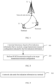
- FIG 4 is a first schematic structural diagram of a PUSCH transmission apparatus according to an embodiment of this application. As shown in FIG 4 , the apparatus includes: a first determining module 410 and a first transmission module 420.
- the first determining module 410 is configured to determine, based on first indication information that is received, a target transmission resource configuration indicated by the first indication information from at least one transmission resource configuration.
- the first transmission module 420 is configured to perform PUSCH transmission based on the target transmission resource configuration.
- the first indication information includes at least one of the following:
- the at least one transmission resource configuration is determined based on at least one of the following:
- the PUSCH transmission apparatus determines, based on the received first indication information by using the first determining module 410, the target transmission resource configuration indicated by the first indication information from the at least one transmission resource configuration, and then may perform PUSCH transmission based on the target transmission resource configuration by using the first transmission module 420.
- the target transmission resource configuration for PUSCH transmission is indicated to the terminal by using at least one of the SRS resource indication information, the TPMI indication information, and the PTRS transmit port indication information, so as to reduce bit overheads for the SRI field and/or TPMI field for the PUSCH transmission resource configuration.
- the SRS resource indication information includes a codepoint value in an SRI field.
- the first determining module is further configured to: based on the codepoint value in the SRI field of the DCI, determine target SRI field codepoint information in at least one piece of SRI field codepoint information; where the at least one piece of SRI field codepoint information is determined by the terminal based on at least one of the following:
- the SRI field codepoint information is associated with at least one SRS resource (SRS resource), or the SRI field codepoint information is associated with at least one SRS resource group (SRS resource group).
- different codepoint values in the SRI field are in one-to-one correspondence to the at least one piece of SRI field codepoint information; and a correspondence between the different codepoint values in the SRI field and the at least one piece of SRI field codepoint information is pre-indicated by a network side, pre-defined by a protocol, pre-configured, or indicated by second signaling, where the second signaling is RRC layer signaling or MAC layer signaling.
- multiple SRS resources or resource groups associated with the SRI field codepoint information belong to different SRS resource sets (SRS resource sets).
- SRS resources in each SRS resource group belong to the same SRS resource set.
- the first determining module is further configured to:
- the first transmission module is further configured to:
- the first transmission module is further configured to:
- the mapping manner includes: the at least one SRS resource or resource group is alternately or sequentially mapped to a plurality of repetition occasions of PUSCH.
- the mapping manner includes: sequentially performing one-to-one mapping of the at least one SRS resource or resource group to a plurality of partial repetition occasions in one repetition occasion of PUSCH, where the plurality of partial repetition occasions form the one repetition occasion.
- a sequence of the at least one SRS resource or resource group is determined based on an association sequence in the target SRI field codepoint information.
- a sequence of the at least one SRS resource or resource group is determined based on an index (SRS resource set ID) of an SRS resource set to which the at least one SRS resource or resource group belongs.
- different SRS resource sets are associated with different CORESETPoolIndex; and different DCIs are from CORESETs associated with the different CORESETPoolIndex.
- the PTRS transmit port indication information includes indication information in a PTRS-DMRS association field.
- the first determining module is further configured to:
- the third signaling includes:
- the first determining module is further configured to:
- the indication information in the PTRS-DMRS association field includes a second value of the PTRS-DMRS association field; and different second values are in one-to-one correspondence to the at least one association relationship.
- the first determining module is further configured to: determine, based on the second value of the PTRS-DMRS association field, that an association relationship corresponding to the second value is the target association relationship.
- the first determining module is further configured to: in a case that the maximum number of PTRS ports is 1 or 2 and the maximum number of transmission ranks is 2, determine that the number of bits of the indication information in the PTRS-DMRS association field is 2 bits.
- the second value of the indication information in the PTRS-DMRS association field includes a third value of the most significant bit MSB and a fourth value of the least significant bit LSB.
- the third value of the most significant bit MSB includes 0 or 1.
- the target association relationship includes: PTRS port 0 is associated with the 1 st scheduled DM-RS port associated with a first SRS resource or SRS resource group; and in a case that the third value of the most significant bit MSB is 1, the target association relationship includes: PTRS port 0 is associated with the 2 nd scheduled DM-RS port associated with the first SRS resource or SRS resource group.
- the fourth value of the least significant bit LSB includes 0 or 1.
- the target association relationship includes: PTRS port 0 is associated with the 1 st scheduled DM-RS port associated with a second SRS resource or SRS resource group; and in a case that the fourth value of the least significant bit LSB is 1, the target association relationship includes: PTRS port 0 is associated with the 2 nd scheduled DM-RS port associated with the second SRS resource or SRS resource group.
- the first determining module is further configured to:
- the first determining module is further configured to: in a case that the maximum number of PTRS ports is 1 and the maximum number of transmission ranks is 3 or 4, determine that the number of bits of the indication information in the PTRS-DMRS association field is 4 bits.
- the second value of the indication information in the PTRS-DMRS association field includes a fifth value of the most significant bit MSB and a sixth value of the least significant bit LSB; and the most significant bit MSB is 2 bits, and the least significant bit LSB is 2 bits.
- the fifth value of the most significant bit MSB is 0, 1, 2, or 3.
- the target association relationship includes: PTRS port 0 is associated with the 1 st scheduled DM-RS port associated with a first SRS resource or SRS resource group;
- the sixth value of the least significant bit LSB is 0, 1, 2, or 3.
- the target association relationship includes: TRS port 0 is associated with the 1 st scheduled DM-RS port associated with a second SRS resource or SRS resource group;
- the first determining module is further configured to:
- the first determining module is further configured to: in a case that the maximum number of PTRS ports is 2 and the maximum number of transmission ranks is 3 or 4, determine that the number of bits of the indication information in the PTRS-DMRS association field is 4 bits.
- the second value of the indication information in the PTRS-DMRS association field includes a seventh value of a first bit, an eighth value of a second bit, a ninth value of a third bit, and a tenth value of a fourth bit.
- the seventh value of the first bit includes 0 or 1.
- the target association relationship includes: shared PTRS port 0 is associated with the 1 st scheduled DM-RS port associated with a first SRS resource or SRS resource group; and in a case that the seventh value of the first bit is 1, the target association relationship includes: shared PTRS port 0 is associated with the 2 nd scheduled DM-RS port associated with the first SRS resource or SRS resource group.
- the eighth value of the second bit includes 0 or 1.
- the target association relationship includes: shared PTRS port 1 is associated with the 1 st scheduled DM-RS port associated with a first SRS resource or SRS resource group; and in a case that the eighth value of the second bit is 1, the target association relationship includes: shared PTRS port 1 is associated with the 2 nd scheduled DM-RS port associated with the first SRS resource or SRS resource group.
- the ninth value of the third bit includes 0 or 1.
- the target association relationship includes: shared PTRS port 0 is associated with the 1 st scheduled DM-RS port associated with a second SRS resource or SRS resource group; and in a case that the ninth value of the third bit is 1, the target association relationship includes: shared PTRS port 0 is associated with the 2 nd scheduled DM-RS port associated with the second SRS resource or SRS resource group.
- the tenth value of the fourth bit includes 0 or 1.
- the target association relationship includes: shared PTRS port 1 is associated with the 1 st scheduled DM-RS port associated with a second SRS resource or SRS resource group; and in a case that the tenth value of the fourth bit is 1, the target association relationship includes: shared PTRS port 1 is associated with the 2 nd scheduled DM-RS port associated with the second SRS resource or SRS resource group.
- the first determining module is further configured to:
- the first transmission module is further configured to: perform transmission based on a first transmission mode or a second transmission mode by using one or more target TPMIs indicated by the TPMI indication information.
- the first transmission mode includes: a first TPMI in the one or more target TPMIs is used for transmission for all PUSCH transmission occasions associated with different SRS resources or SRS resource groups.
- the first TPMI is determined based on the TPMI indication information.
- the TPMI indication information includes:
- the second transmission mode includes: different TPMIs in the one or more target TPMIs are used for transmission for PUSCH transmission occasions associated with different SRS resources or SRS resource groups.
- the TPMI indication information includes:
- the first transmission module is further configured to:
- the sixth signaling includes RRC configuration information and/or MAC CE indication signaling.
- the SRS resource indication information and/or TPMI indication information is associated with first signaling.
- an association relationship between the TPMI indication information and the first signaling includes: in a case that all SRI field codepoint information contained in the first signaling is associated with only one SRS resource or SRS resources associated with all the SRI field codepoint information belong to one SRS resource set, the TPMI indication information is in one-to-one correspondence to PUSCH repetition occasions.
- the target transmission resource configuration for PUSCH transmission is indicated to the terminal by using at least one of the SRS resource indication information, the TPMI indication information, and the PTRS transmit port indication information, so as to reduce bit overheads for the SRI field and/or TPMI field for the PUSCH transmission resource configuration.
- the PUSCH transmission apparatus in this embodiment of this application may be an apparatus or an electric device having an operating system, or may be a component, an integrated circuit, or a chip in a terminal.
- the electric device may be a mobile terminal or a non-mobile terminal.
- the mobile terminal may include but is not limited to the types of the terminal 11 listed above, and the non-mobile terminal may be a server, a network attached storage (Network Attached Storage, NAS), a personal computer (personal computer, PC), a television (television, TV), a teller machine, a self-service machine, or the like, which is not specifically limited in this embodiment of this application.
- Network Attached Storage Network Attached Storage
- the PUSCH transmission apparatus provided in this embodiment of this application can implement the processes implemented in the method embodiment in FIG. 2 , with the same technical effects achieved. To avoid repetition, details are not described herein again.
- FIG. 5 is a second schematic structural diagram of a PUSCH transmission apparatus according to an embodiment of this application. As shown in FIG. 5 , the apparatus includes: a first sending module 510.
- the first sending module 510 is configured to send first indication information to a terminal.
- the first indication information is used to instruct the terminal to determine a target transmission resource configuration indicated by the first indication information from at least one transmission resource configuration; and the first indication information includes at least one of the following:
- the at least one transmission resource configuration is determined based on at least one of the following:
- the PUSCH transmission apparatus sends the first indication information to the terminal by using the first sending module 510, so as to instruct the terminal to determine the target transmission resource configuration indicated by the first indication information from the at least one transmission resource configuration.
- the target transmission resource configuration for PUSCH transmission is indicated to the terminal by using at least one of the SRS resource indication information, the TPMI indication information, and the PTRS transmit port indication information, so as to reduce bit overheads for the SRI field and/or TPMI field for the PUSCH transmission resource configuration.
- the SRS resource indication information includes a codepoint value in an SRI field.
- the codepoint value in the SRI field is used to indicate target SRI field codepoint information in at least one piece of SRI field codepoint information; where the at least one piece of SRI field codepoint information is determined by the terminal based on at least one of the following:
- the SRI field codepoint information is associated with at least one SRS resource (SRS resource), or the SRI field codepoint information is associated with at least one SRS resource group (SRS resource group).
- different codepoint values in the SRI field are in one-to-one correspondence to the at least one piece of SRI field codepoint information; and a correspondence between the different codepoint values in the SRI field and the at least one piece of SRI field codepoint information is pre-indicated by a network side, pre-defined by a protocol, pre-configured, or indicated by second signaling, where the second signaling is RRC layer signaling or MAC layer signaling.
- multiple SRS resources or resource groups associated with the SRI field codepoint information belong to different SRS resource sets (SRS resource sets).
- SRS resources in each SRS resource group belong to the same SRS resource set.
- a sequence of the at least one SRS resource or resource group is determined based on an association sequence in the target SRI field codepoint information.
- a sequence of the at least one SRS resource or resource group is determined based on an index (SRS resource set ID) of an SRS resource set to which the at least one SRS resource or resource group belongs.
- different SRS resource sets are associated with different CORESETPoolIndex; and different DCIs are from CORESETs associated with the different CORESETPoolIndex.
- the PTRS transmit port indication information includes indication information in a PTRS-DMRS association field.
- the indication information in the PTRS-DMRS association field is used for determining a target association relationship in at least one association relationship between PTRS ports and DMRS transmit port.
- the DMRS transmit port is associated with an SRS resource or SRS resource group for PUSCH transmission.
- the third signaling includes:
- the indication information in the PTRS-DMRS association field includes a second value of the PTRS-DMRS association field; and different second values are in one-to-one correspondence to the at least one association relationship.
- the second value of the indication information in the PTRS-DMRS association field includes a third value of the most significant bit MSB and a fourth value of the least significant bit LSB.
- the third value of the most significant bit MSB includes 0 or 1.
- the target association relationship includes: PTRS port 0 is associated with the 1 st scheduled DM-RS port associated with a first SRS resource or SRS resource group; and in a case that the third value of the most significant bit MSB is 1, the target association relationship includes: PTRS port 0 is associated with the 2 nd scheduled DM-RS port associated with the first SRS resource or SRS resource group.
- the fourth value of the least significant bit LSB includes 0 or 1.
- the target association relationship includes: PTRS port 0 is associated with the 1 st scheduled DM-RS port associated with a second SRS resource or SRS resource group; and in a case that the fourth value of the least significant bit LSB is 1, the target association relationship includes: PTRS port 0 is associated with the 2 nd scheduled DM-RS port associated with the second SRS resource or SRS resource group.
- determining that the number of bits of the indication information in the PTRS-DMRS association field is 4 bits.
- the second value of the indication information in the PTRS-DMRS association field includes a fifth value of the most significant bit MSB and a sixth value of the least significant bit LSB; and the most significant bit MSB is 2 bits, and the least significant bit LSB is 2 bits.
- the fifth value of the most significant bit MSB is 0, 1, 2, or 3.
- the target association relationship includes: PTRS port 0 is associated with the 1 st scheduled DM-RS port associated with a first SRS resource or SRS resource group;
- the sixth value of the least significant bit LSB is 0, 1, 2, or 3.
- the number of bits of the indication information in the PTRS-DMRS association field is 4 bits.
- the second value of the indication information in the PTRS-DMRS association field includes a seventh value of a first bit, an eighth value of a second bit, a ninth value of a third bit, and a tenth value of a fourth bit.
- the seventh value of the first bit includes 0 or 1.
- the target association relationship includes: shared PTRS port 0 is associated with the 1 st scheduled DM-RS port associated with a first SRS resource or SRS resource group; and in a case that the seventh value of the first bit is 1, the target association relationship includes: shared PTRS port 0 is associated with the 2 nd scheduled DM-RS port associated with the first SRS resource or SRS resource group.
- the eighth value of the second bit includes 0 or 1.
- the target association relationship includes: shared PTRS port 1 is associated with the 1 st scheduled DM-RS port associated with a first SRS resource or SRS resource group; and in a case that the eighth value of the second bit is 1, the target association relationship includes: shared PTRS port 1 is associated with the 2 nd scheduled DM-RS port associated with the first SRS resource or SRS resource group.
- the ninth value of the third bit includes 0 or 1.
- the target association relationship includes: shared PTRS port 0 is associated with the 1 st scheduled DM-RS port associated with a second SRS resource or SRS resource group; and in a case that the ninth value of the third bit is 1, the target association relationship includes: shared PTRS port 0 is associated with the 2 nd scheduled DM-RS port associated with the second SRS resource or SRS resource group.
- the tenth value of the fourth bit includes 0 or 1.
- the target association relationship includes: shared PTRS port 1 is associated with the 1 st scheduled DM-RS port associated with a second SRS resource or SRS resource group; and in a case that the tenth value of the fourth bit is 1, the target association relationship includes: shared PTRS port 1 is associated with the 2 nd scheduled DM-RS port associated with the second SRS resource or SRS resource group.
- an association relationship between the TPMI indication information and the first signaling includes: in a case that all SRI field codepoint information contained in the first signaling is associated with only one SRS resource or SRS resources associated with all the SRI field codepoint information belong to one SRS resource set, the TPMI indication information is in one-to-one correspondence to PUSCH repetition occasions.
- the target transmission resource configuration for PUSCH transmission is indicated to the terminal by using at least one of the SRS resource indication information, the TPMI indication information, and the PTRS transmit port indication information, so as to reduce bit overheads for the SRI field and/or TPMI field for the PUSCH transmission resource configuration.
- the PUSCH transmission apparatus in this embodiment of this application may be an apparatus, or may be a component, an integrated circuit, or a chip in the terminal.
- the apparatus may be a mobile terminal or a non-mobile terminal.
- the mobile terminal may include but is not limited to the types of the terminal 11 listed above, and the non-mobile terminal may be a server, a network attached storage (Network Attached Storage, NAS), a personal computer (personal computer, PC), a television (television, TV), a teller machine, a self-service machine, or the like, which is not specifically limited in this embodiment of this application.
- Network Attached Storage Network Attached Storage
- the PUSCH transmission apparatus in this embodiment of this application may be an apparatus having an operating system.
- the operating system may be an Android (Android) operating system, an iOS operating system, or other possible operating systems, and is not specifically limited in the embodiments of this application.
- the PUSCH transmission apparatus provided in this embodiment of this application can implement the processes implemented in the method embodiment in FIG. 3 , with the same technical effects achieved. To avoid repetition, details are not described herein again.
- FIG. 6 is a schematic structural diagram of a communication device provided in an embodiment of this application.
- the communication device 600 includes a processor 601, a memory 602, and a program or instructions stored in the memory 602 and capable of running on the processor 601.
- the communication device 600 is a terminal and when the program or the instructions are executed by the processor 601, the processes of the foregoing method embodiments are implemented, with the same technical effects achieved.
- the communication device 600 is a network-side device and when the program or the instructions are executed by the processor 601, the processes of the foregoing method embodiments are implemented, with the same technical effects achieved. To avoid repetition, details are not described herein again.
- FIG. 7 is a schematic diagram of a hardware structure of a terminal device according to an embodiment of this application.
- the terminal 700 includes but is not limited to at least part of components such as a radio frequency unit 701, a network module 702, an audio output unit 703, an input unit 704, a sensor 705, a display unit 706, a user input unit 707, an interface unit 708, a memory 709, and a processor 710.
- the terminal 700 may further include a power supply (for example, a battery) supplying power to the components, and the power supply may be logically connected to the processor 710 through a power management system. In this way, functions such as charge management, discharge management, and power consumption management are implemented by using the power management system.
- a power supply for example, a battery
- functions such as charge management, discharge management, and power consumption management are implemented by using the power management system.
- the structure of the terminal shown in FIG. 7 does not constitute any limitation on the terminal.
- the terminal may include more or fewer components than those shown in the figure, or a combination of some components, or the components disposed differently. Details are not described herein again.
- the input unit 704 may include a graphics processing unit (Graphics Processing Unit, GPU) 7041 and a microphone 7042.
- the graphics processing unit 7041 processes image data of a still picture or video obtained by an image capture apparatus (such as a camera) in a video capture mode or an image capture mode.
- the display unit 706 may include a display panel 7061, and the display panel 7061 may be configured in a form of a liquid crystal display, an organic light-emitting diode, and the like.
- the user input unit 707 may include a touch panel 7071 and other input devices 7072.
- the touch panel 7071 is also referred to as a touchscreen.
- the touch panel 7071 may include two parts: a touch detection apparatus and a touch controller.
- the other input devices 7072 may include but are not limited to a physical keyboard, a function key (such as a volume control key or a power on/off key), a trackball, a mouse, a joystick, and the like. Details are not described herein.
- the radio frequency unit 701 receives information from the communication peer and sends it to the processor 710 for processing; and sends the information to be transmitted to the communication peer.
- the radio frequency unit 701 includes but is not limited to an antenna, at least one amplifier, a transceiver, a coupler, a low noise amplifier, a duplexer, and the like.
- the memory 709 may be configured to store software programs or instructions and various data.
- the memory 709 may include a program or instruction storage area and a data storage area.
- the program or instruction storage area may store an operating system, an application program or instruction required by at least one function (for example, a sound playback function or an image playback function), and the like.
- the memory 709 may include a high-speed random access memory, and may further include a non-volatile memory.
- the non-volatile memory may be a read-only memory (Read-Only memory, ROM), a programmable read-only memory (Programmable ROM, PROM), an erasable programmable read-only memory (Erasable PROM, EPROM), an electrically erasable programmable read-only memory (Electrically EPROM, EEPROM), or a flash memory, for example, at least one disk storage device, a flash memory device, or another volatile solid-state storage device.
- ROM Read-Only memory
- PROM programmable read-only memory
- Erasable PROM Erasable PROM
- EPROM electrically erasable programmable read-only memory
- EEPROM electrically erasable programmable read-only memory
- flash memory for example, at least one disk storage device, a flash memory device, or another volatile solid-state storage device.
- the processor 710 may include one or more processing units.
- an application processor and a modem processor may be integrated in the processor 710.
- the application processor primarily processes an operating system, user interfaces, application programs or instructions, and the like.
- the modem processor primarily processes radio communication, for example, being a baseband processor. It can be understood that the modem processor may alternatively be not integrated in the processor 710.
- the processor 710 is configured to:
- the first indication information includes at least one of the following:
- the at least one transmission resource configuration is determined based on at least one of the following:
- the target transmission resource configuration for PUSCH transmission is indicated to the terminal by using at least one of the SRS resource indication information, the TPMI indication information, and the PTRS transmit port indication information, so as to reduce bit overheads for the SRI field and/or TPMI field for the PUSCH transmission resource configuration.
- the SRS resource indication information includes a codepoint value in an SRI field.
- the determining, by the terminal based on the first indication information in the DCI, the target transmission resource configuration indicated by the first indication information includes: based on the codepoint value in the SRI field of the DCI, determining target SRI field codepoint information in at least one piece of SRI field codepoint information; where the at least one piece of SRI field codepoint information is determined by the terminal based on at least one of the following:
- the SRI field codepoint information is associated with at least one SRS resource (SRS resource), or the SRI field codepoint information is associated with at least one SRS resource group (SRS resource group).
- different codepoint values in the SRI field are in one-to-one correspondence to the at least one piece of SRI field codepoint information; and a correspondence between the different codepoint values in the SRI field and the at least one piece of SRI field codepoint information is pre-indicated by a network side, pre-defined by a protocol, pre-configured, or indicated by second signaling, where the second signaling is RRC layer signaling or MAC layer signaling.
- multiple SRS resources or resource groups associated with the SRI field codepoint information belong to different SRS resource sets (SRS resource sets).
- SRS resources in each SRS resource group belong to the same SRS resource set.
- the determining, based on the codepoint value in the SRI field of DCI, target SRI field codepoint information in at least one piece of SRI field codepoint information includes:
- the performing PUSCH transmission based on the target transmission resource configuration includes:
- the processor 710 is configured to:
- the mapping manner includes: the at least one SRS resource or resource group is alternately or sequentially mapped to a plurality of repetition occasions of PUSCH.
- the mapping manner includes: sequentially performing one-to-one mapping of the at least one SRS resource or resource group to a plurality of partial repetition occasions in one repetition occasion of PUSCH, where the plurality of partial repetition occasions form the one repetition occasion.
- a sequence of the at least one SRS resource or resource group is determined based on an association sequence in the target SRI field codepoint information.
- a sequence of the at least one SRS resource or resource group is determined based on an index (SRS resource set ID) of an SRS resource set to which the at least one SRS resource or resource group belongs.
- different SRS resource sets are associated with different CORESETPoolIndex; and different DCIs are from CORESETs associated with the different CORESETPoolIndex.
- the PTRS transmit port indication information includes indication information in a PTRS-DMRS association field.
- the determining, by the terminal based on the first indication information in the DCI, the target transmission resource configuration indicated by the first indication information includes:
- the DMRS transmit port is associated with an SRS resource or SRS resource group for PUSCH transmission.
- the third signaling includes:
- the determining, based on third signaling of an RRC layer or a MAC layer, indication information in a PTRS-DMRS association field of DCI includes:
- the indication information in the PTRS-DMRS association field includes a second value of the PTRS-DMRS association field; and different second values are in one-to-one correspondence to the at least one association relationship.
- the processor 710 is configured to: determine, based on the second value of the PTRS-DMRS association field, that an association relationship corresponding to the second value is the target association relationship.
- the processor 710 is configured to: in a case that the maximum number of PTRS ports is 1 or 2 and the maximum number of transmission ranks is 2, determine that the number of bits of the indication information in the PTRS-DMRS association field is 2 bits.
- the second value of the indication information in the PTRS-DMRS association field includes a third value of the most significant bit MSB and a fourth value of the least significant bit LSB.
- the third value of the most significant bit MSB includes 0 or 1.
- the target association relationship includes: PTRS port 0 is associated with the 1 st scheduled DM-RS port associated with a first SRS resource or SRS resource group; and in a case that the third value of the most significant bit MSB is 1, the target association relationship includes: PTRS port 0 is associated with the 2 nd scheduled DM-RS port associated with the first SRS resource or SRS resource group.
- the fourth value of the least significant bit LSB includes 0 or 1.
- the target association relationship includes: PTRS port 0 is associated with the 1 st scheduled DM-RS port associated with a second SRS resource or SRS resource group; and in a case that the fourth value of the least significant bit LSB is 1, the target association relationship includes: PTRS port 0 is associated with the 2 nd scheduled DM-RS port associated with the second SRS resource or SRS resource group.
- the processor 710 is configured to:
- the processor 710 is configured to: in a case that the maximum number of PTRS ports is 1 and the maximum number of transmission ranks is 3 or 4, determine that the number of bits of the indication information in the PTRS-DMRS association field is 4 bits.
- the second value of the indication information in the PTRS-DMRS association field includes a fifth value of the most significant bit MSB and a sixth value of the least significant bit LSB; and the most significant bit MSB is 2 bits, and the least significant bit LSB is 2 bits.
- the fifth value of the most significant bit MSB is 0, 1, 2, or 3.
- the target association relationship includes: PTRS port 0 is associated with the 1 st scheduled DM-RS port associated with a first SRS resource or SRS resource group;
- the sixth value of the least significant bit LSB is 0, 1, 2, or 3.
- the processor 710 is configured to:
- the processor 710 is configured to: in a case that the maximum number of PTRS ports is 2 and the maximum number of transmission ranks is 3 or 4, determine that the number of bits of the indication information in the PTRS-DMRS association field is 4 bits.
- the second value of the indication information in the PTRS-DMRS association field includes a seventh value of a first bit, an eighth value of a second bit, a ninth value of a third bit, and a tenth value of a fourth bit.
- the seventh value of the first bit includes 0 or 1.
- the target association relationship includes: shared PTRS port 0 is associated with the 1 st scheduled DM-RS port associated with a first SRS resource or SRS resource group; and in a case that the seventh value of the first bit is 1, the target association relationship includes: shared PTRS port 0 is associated with the 2 nd scheduled DM-RS port associated with the first SRS resource or SRS resource group.
- the eighth value of the second bit includes 0 or 1.
- the target association relationship includes: shared PTRS port 1 is associated with the 1 st scheduled DM-RS port associated with a first SRS resource or SRS resource group; and in a case that the eighth value of the second bit is 1, the target association relationship includes: shared PTRS port 1 is associated with the 2 nd scheduled DM-RS port associated with the first SRS resource or SRS resource group.
- the ninth value of the third bit includes 0 or 1.
- the target association relationship includes: shared PTRS port 0 is associated with the 1 st scheduled DM-RS port associated with a second SRS resource or SRS resource group; and in a case that the ninth value of the third bit is 1, the target association relationship includes: shared PTRS port 0 is associated with the 2 nd scheduled DM-RS port associated with the second SRS resource or SRS resource group.
- the tenth value of the fourth bit includes 0 or 1.
- the target association relationship includes: shared PTRS port 1 is associated with the 1 st scheduled DM-RS port associated with a second SRS resource or SRS resource group; and in a case that the tenth value of the fourth bit is 1, the target association relationship includes: shared PTRS port 1 is associated with the 2 nd scheduled DM-RS port associated with the second SRS resource or SRS resource group.
- the processor 710 is configured to:
- the processor 710 is configured to: perform transmission based on a first transmission mode or a second transmission mode by using one or more target TPMIs indicated by the TPMI indication information.
- the first transmission mode includes: a first TPMI in the one or more target TPMIs is used for transmission for all PUSCH transmission occasions associated with different SRS resources or SRS resource groups.
- the first TPMI is determined based on the TPMI indication information.
- the TPMI indication information includes:
- the second transmission mode includes: different TPMIs in the one or more target TPMIs are used for transmission for PUSCH transmission occasions associated with different SRS resources or SRS resource groups.
- the TPMI indication information includes:
- the processor 710 is configured to:
- the sixth signaling includes RRC configuration information and/or MAC CE indication signaling.
- the SRS resource indication information and/or TPMI indication information is associated with first signaling.
- an association relationship between the TPMI indication information and the first signaling includes: in a case that all SRI field codepoint information contained in the first signaling is associated with only one SRS resource or SRS resources associated with all the SRI field codepoint information belong to one SRS resource set, the TPMI indication information is in one-to-one correspondence to PUSCH repetition occasions.
- the target transmission resource configuration for PUSCH transmission is indicated to the terminal by using at least one of the SRS resource indication information, the TPMI indication information, and the PTRS transmit port indication information, so as to reduce bit overheads for the SRI field and/or TPMI field for the PUSCH transmission resource configuration.
- the terminal device embodiment in the embodiments of this application is a product embodiment corresponding to the foregoing method embodiment, and all the implementations in the foregoing method embodiment are applicable to the terminal device embodiment, with the same or similar technical effects achieved. Details are not repeated herein.
- FIG. 8 is a schematic diagram of a hardware structure of a network-side device according to an embodiment of this application.
- the network-side device 800 includes an antenna 801, a radio frequency apparatus 802, and a baseband apparatus 803.
- the antenna 801 is connected to the radio frequency apparatus 802.
- the radio frequency apparatus 802 receives information by using the antenna 801, and sends the received information to the baseband apparatus 803 for processing.
- the baseband apparatus 803 processes to-be-sent information, and sends the information to the radio frequency apparatus 802; and the radio frequency apparatus 802 processes the received information and then sends the information out by using the antenna 801.
- the frequency band processing apparatus may be located in the baseband apparatus 803.
- the method performed by the network-side device in the foregoing embodiments may be implemented in the baseband apparatus 803, and the baseband apparatus 803 includes a processor 804 and a memory 805.
- the baseband apparatus 803 may include, for example, at least one baseband board, where a plurality of chips are disposed on the baseband board. As shown in FIG. 8 , one of the chips, for example, the processor 804, is connected to the memory 805, to invoke a program in the memory 805 to perform the operation of the network device shown in the foregoing method embodiments.
- the baseband apparatus 803 may further include a network interface 806, configured to exchange information with the radio frequency apparatus 802, where the interface is, for example, a common public radio interface (common public radio interface, CPRI for short).
- a network interface 806 configured to exchange information with the radio frequency apparatus 802, where the interface is, for example, a common public radio interface (common public radio interface, CPRI for short).
- the network-side device in this embodiment of this application further includes: instructions or a program stored in the memory 805 and capable of running on the processor 804.
- the processor 804 invokes the instructions or program in the memory 805 to execute the method executed by the modules shown in FIG. 5 , with the same technical effects achieved. To avoid repetition, details are not repeated herein.
- the processor 804 is configured to: send first indication information to a terminal.
- the first indication information is used to instruct the terminal to determine a target transmission resource configuration indicated by the first indication information from at least one transmission resource configuration;
- the first indication information includes at least one of the following:
- the at least one transmission resource configuration is determined based on at least one of the following:
- the target transmission resource configuration for PUSCH transmission is indicated to the terminal by using at least one of the SRS resource indication information, the TPMI indication information, and the PTRS transmit port indication information, so as to reduce bit overheads for the SRI field and/or TPMI field for the PUSCH transmission resource configuration.
- the SRS resource indication information includes a codepoint value in an SRI field.
- the codepoint value in the SRI field is used to indicate target SRI field codepoint information in at least one piece of SRI field codepoint information; where the at least one piece of SRI field codepoint information is determined by the terminal based on at least one of the following:
- the SRI field codepoint information is associated with at least one SRS resource (SRS resource), or the SRI field codepoint information is associated with at least one SRS resource group (SRS resource group).
- different codepoint values in the SRI field are in one-to-one correspondence to the at least one piece of SRI field codepoint information; and a correspondence between the different codepoint values in the SRI field and the at least one piece of SRI field codepoint information is pre-indicated by a network side, pre-defined by a protocol, pre-configured, or indicated by second signaling, where the second signaling is RRC layer signaling or MAC layer signaling.
- multiple SRS resources or resource groups associated with the SRI field codepoint information belong to different SRS resource sets (SRS resource sets).
- SRS resources in each SRS resource group belong to the same SRS resource set.
- a sequence of the at least one SRS resource or resource group is determined based on an association sequence in the target SRI field codepoint information.
- a sequence of the at least one SRS resource or resource group is determined based on an index (SRS resource set ID) of an SRS resource set to which the at least one SRS resource or resource group belongs.
- different SRS resource sets are associated with different CORESETPoolIndex; and different DCIs are from CORESETs associated with the different CORESETPoolIndex.
- the PTRS transmit port indication information includes indication information in a PTRS-DMRS association field.
- the indication information in the PTRS-DMRS association field is used for determining a target association relationship in at least one association relationship between PTRS ports and DMRS transmit port.
- the DMRS transmit port is associated with an SRS resource or SRS resource group for PUSCH transmission.
- the third signaling includes:
- the indication information in the PTRS-DMRS association field includes a second value of the PTRS-DMRS association field; and different second values are in one-to-one correspondence to the at least one association relationship.
- the second value of the indication information in the PTRS-DMRS association field includes a third value of the most significant bit MSB and a fourth value of the least significant bit LSB.
- the third value of the most significant bit MSB includes 0 or 1.
- the target association relationship includes: PTRS port 0 is associated with the 1 st scheduled DM-RS port associated with a first SRS resource or SRS resource group; and in a case that the third value of the most significant bit MSB is 1, the target association relationship includes: PTRS port 0 is associated with the 2 nd scheduled DM-RS port associated with the first SRS resource or SRS resource group.
- the fourth value of the least significant bit LSB includes 0 or 1.
- the target association relationship includes: PTRS port 0 is associated with the 1 st scheduled DM-RS port associated with a second SRS resource or SRS resource group; and in a case that the fourth value of the least significant bit LSB is 1, the target association relationship includes: PTRS port 0 is associated with the 2 nd scheduled DM-RS port associated with the second SRS resource or SRS resource group.
- determining that the number of bits of the indication information in the PTRS-DMRS association field is 4 bits.
- the second value of the indication information in the PTRS-DMRS association field includes a fifth value of the most significant bit MSB and a sixth value of the least significant bit LSB; and the most significant bit MSB is 2 bits, and the least significant bit LSB is 2 bits.
- the fifth value of the most significant bit MSB is 0, 1, 2, or 3.
- the target association relationship includes: PTRS port 0 is associated with the 1 st scheduled DM-RS port associated with a first SRS resource or SRS resource group;
- the sixth value of the least significant bit LSB is 0, 1, 2, or 3.
- the number of bits of the indication information in the PTRS-DMRS association field is 4 bits.
- the second value of the indication information in the PTRS-DMRS association field includes a seventh value of a first bit, an eighth value of a second bit, a ninth value of a third bit, and a tenth value of a fourth bit.
- the seventh value of the first bit includes 0 or 1.
- the target association relationship includes: shared PTRS port 0 is associated with the 1 st scheduled DM-RS port associated with a first SRS resource or SRS resource group; and in a case that the seventh value of the first bit is 1, the target association relationship includes: shared PTRS port 0 is associated with the 2 nd scheduled DM-RS port associated with the first SRS resource or SRS resource group.
- the eighth value of the second bit includes 0 or 1.
- the target association relationship includes: shared PTRS port 1 is associated with the 1 st scheduled DM-RS port associated with a first SRS resource or SRS resource group; and in a case that the eighth value of the second bit is 1, the target association relationship includes: shared PTRS port 1 is associated with the 2 nd scheduled DM-RS port associated with the first SRS resource or SRS resource group.
- the ninth value of the third bit includes 0 or 1.
- the target association relationship includes: shared PTRS port 0 is associated with the 1 st scheduled DM-RS port associated with a second SRS resource or SRS resource group; and in a case that the ninth value of the third bit is 1, the target association relationship includes: shared PTRS port 0 is associated with the 2 nd scheduled DM-RS port associated with the second SRS resource or SRS resource group.
- the tenth value of the fourth bit includes 0 or 1.
- the target association relationship includes: shared PTRS port 1 is associated with the 1 st scheduled DM-RS port associated with a second SRS resource or SRS resource group; and in a case that the tenth value of the fourth bit is 1, the target association relationship includes: shared PTRS port 1 is associated with the 2 nd scheduled DM-RS port associated with the second SRS resource or SRS resource group.
- an association relationship between the TPMI indication information and the first signaling includes: in a case that all SRI field codepoint information contained in the first signaling is associated with only one SRS resource or SRS resources associated with all the SRI field codepoint information belong to one SRS resource set, the TPMI indication information is in one-to-one correspondence to PUSCH repetition occasions.
- the target transmission resource configuration for PUSCH transmission is indicated to the terminal by using at least one of the SRS resource indication information, the TPMI indication information, and the PTRS transmit port indication information, so as to reduce bit overheads for the SRI field and/or TPMI field for the PUSCH transmission resource configuration.
- the network-side device embodiment in the embodiments of this application is a product embodiment corresponding to the foregoing method embodiment, and all the implementations in the foregoing method embodiment are applicable to the network-side device embodiment, with the same or similar technical effects achieved. Details are not repeated herein.
- An embodiment of this application further provides a readable storage medium, where a program or an instruction is stored in the readable storage medium.
- a program or an instruction is stored in the readable storage medium.
- the processor is a processor in the terminal described in the foregoing embodiments.
- the readable storage medium includes a computer-readable storage medium, for example, a computer read-only memory (Read-Only Memory, ROM), a random access memory (Random Access Memory, RAM), a magnetic disk, or an optical disc.
- An embodiment of this application further provides a chip, where the chip includes a processor and a communications interface.
- the communications interface is coupled to the processor, and the processor is configured to run a program or an instruction of a network-side device to implement the processes of the foregoing PUSCH transmission method embodiments, with the same technical effects achieved. To avoid repetition, details are not described herein again.
- the chip mentioned in the embodiments of this application may also be referred to as a system-level chip, a system chip, a chip system, a system-on-chip, or the like.
- execution of the functions are not limited to the order shown or described, and the functions may alternatively be executed in a substantially simultaneous manner or in a reverse order.
- the described method may be performed in an order different from that described, and steps may be added, omitted, or combined.
- features described with reference to some examples may be combined in other examples.
- the methods in the foregoing embodiments may be implemented by using software in combination with a necessary common hardware platform, and certainly may alternatively be implemented by using hardware. However, in most cases, the former is a preferred implementation.
- the technical solutions of this application essentially or the part contributing to the prior art may be implemented in a form of a software product.
- the software product is stored in a storage medium (such as a ROM/RAM, a magnetic disk, or an optical disc), and includes several instructions for instructing a terminal (which may be a mobile phone, a computer, a server, an air conditioner, a network device, or the like) to perform the methods described in the embodiments of this application.
Landscapes
- Engineering & Computer Science (AREA)
- Signal Processing (AREA)
- Computer Networks & Wireless Communication (AREA)
- Physics & Mathematics (AREA)
- Mathematical Physics (AREA)
- Mobile Radio Communication Systems (AREA)
Applications Claiming Priority (2)
| Application Number | Priority Date | Filing Date | Title |
|---|---|---|---|
| CN202110057894.8A CN114765879B (zh) | 2021-01-15 | 2021-01-15 | Pusch传输方法、装置、设备及存储介质 |
| PCT/CN2022/072140 WO2022152271A1 (fr) | 2021-01-15 | 2022-01-14 | Procédé et appareil de transmission de canal pusch, et dispositif et support de stockage |
Publications (2)
| Publication Number | Publication Date |
|---|---|
| EP4262307A1 true EP4262307A1 (fr) | 2023-10-18 |
| EP4262307A4 EP4262307A4 (fr) | 2024-05-08 |
Family
ID=82364874
Family Applications (1)
| Application Number | Title | Priority Date | Filing Date |
|---|---|---|---|
| EP22739146.3A Pending EP4262307A4 (fr) | 2021-01-15 | 2022-01-14 | Procédé et appareil de transmission de canal pusch, et dispositif et support de stockage |
Country Status (6)
| Country | Link |
|---|---|
| US (1) | US20230362927A1 (fr) |
| EP (1) | EP4262307A4 (fr) |
| JP (1) | JP7665759B2 (fr) |
| KR (1) | KR102942167B1 (fr) |
| CN (1) | CN114765879B (fr) |
| WO (1) | WO2022152271A1 (fr) |
Families Citing this family (21)
| Publication number | Priority date | Publication date | Assignee | Title |
|---|---|---|---|---|
| US12127190B2 (en) * | 2021-04-02 | 2024-10-22 | Telefonaktiebolaget Lm Ericsson (Publ) | Systems and methods for non-codebook based multi-TRP PUSCH |
| CN117200958A (zh) * | 2021-04-06 | 2023-12-08 | 苹果公司 | 用于多trp操作的trp专用pusch传输 |
| CN115735343B (zh) * | 2021-06-29 | 2025-05-06 | 北京小米移动软件有限公司 | 上行传输方法、装置、设备及可读存储介质 |
| WO2023081102A1 (fr) * | 2021-11-08 | 2023-05-11 | Intel Corporation | Techniques pour une opération améliorée de signal de référence de suivi de phase |
| US12574178B2 (en) * | 2022-08-02 | 2026-03-10 | Qualcomm Incorporated | Techniques for interpreting downlink control information (DCI) fields in non-codebook-based multi-panel deployments with dynamic panel switching |
| EP4572253A4 (fr) * | 2022-08-10 | 2025-08-20 | Beijing Xiaomi Mobile Software Co Ltd | Procédé d'indication de précodage, appareil, et support de stockage |
| EP4572212A1 (fr) * | 2022-08-11 | 2025-06-18 | LG Electronics Inc. | Procédé et dispositif de transmission et de réception de ptrs dans un système de communication sans fil |
| CN119948798A (zh) * | 2022-09-26 | 2025-05-06 | Lg电子株式会社 | 用于执行通信系统中的上行链路发送和接收的方法和装置 |
| CN117811626A (zh) * | 2022-10-01 | 2024-04-02 | 华为技术有限公司 | 通信方法、装置及存储介质 |
| CN118041498A (zh) * | 2022-11-07 | 2024-05-14 | 大唐移动通信设备有限公司 | 一种信息确定方法、装置及可读存储介质 |
| CN118074870A (zh) * | 2022-11-11 | 2024-05-24 | 维沃移动通信有限公司 | 信息确定方法、装置及通信设备 |
| EP4604636A4 (fr) * | 2022-12-22 | 2025-11-19 | Guangdong Oppo Mobile Telecommunications Corp Ltd | Procédé et appareil de traitement d'informations, dispositif terminal et dispositif de réseau |
| WO2024210183A1 (fr) * | 2023-04-06 | 2024-10-10 | シャープ株式会社 | Dispositif terminal, dispositif de station de base et procédé de communication |
| CN120712871A (zh) * | 2023-05-15 | 2025-09-26 | Oppo广东移动通信有限公司 | 信息传输方法及装置、终端设备、网络设备 |
| KR20240175063A (ko) * | 2023-06-12 | 2024-12-19 | 삼성전자주식회사 | 무선 통신 시스템에서 pusch 자원 할당 방법 및 장치 |
| CN119382843A (zh) * | 2023-07-25 | 2025-01-28 | 维沃移动通信有限公司 | 探测参考信号传输方法、设备及存储介质 |
| WO2025065187A1 (fr) * | 2023-09-25 | 2025-04-03 | 富士通株式会社 | Appareils et procédés de transmission de données et de réception de données |
| CN119946870A (zh) * | 2023-11-03 | 2025-05-06 | 华为技术有限公司 | 通信方法、装置及存储介质 |
| CN120239076A (zh) * | 2023-12-29 | 2025-07-01 | 维沃移动通信有限公司 | 上行传输的方法、终端及网络侧设备 |
| CN118802087B (zh) * | 2024-03-29 | 2026-01-30 | 中国移动通信有限公司研究院 | 传输处理方法、装置、设备及介质 |
| CN119835780A (zh) * | 2024-06-01 | 2025-04-15 | 荣耀终端股份有限公司 | 一种被用于无线通信的节点中的方法和装置 |
Family Cites Families (17)
| Publication number | Priority date | Publication date | Assignee | Title |
|---|---|---|---|---|
| WO2018170691A1 (fr) * | 2017-03-20 | 2018-09-27 | Oppo广东移动通信有限公司 | Procédé de transmission de liaison montante, dispositif terminal et dispositif de réseau |
| RU2741628C1 (ru) * | 2017-08-04 | 2021-01-28 | Гуандун Оппо Мобайл Телекоммьюникейшнз Корп., Лтд. | Способ беспроводной связи и терминальное устройство |
| US10965421B2 (en) * | 2017-11-16 | 2021-03-30 | Lg Electronics Inc. | Method for transmitting and receiving uplink phase tracking reference signal and devices supporting the same |
| CN110034904B (zh) * | 2018-01-11 | 2022-01-04 | 维沃移动通信有限公司 | 相位跟踪参考信号关联指示及发送方法、网络设备和终端 |
| CN110266626A (zh) * | 2018-03-12 | 2019-09-20 | 维沃移动通信有限公司 | 相位跟踪参考信号ptrs的传输方法、终端及网络设备 |
| CN110351037B (zh) * | 2018-04-03 | 2020-09-01 | 展讯通信(上海)有限公司 | 基于非码本上行pusch传输的pt-rs端口指示方法、装置及基站 |
| US11729782B2 (en) * | 2018-06-11 | 2023-08-15 | Apple Inc. | Enhanced uplink beam management |
| US11044062B2 (en) * | 2018-07-13 | 2021-06-22 | Apple Inc. | Methods to determine parameters related to phase tracking reference signals (PT-RS) based on a type of radio network temporary identifier (RNTI) |
| EP3697014A1 (fr) * | 2019-02-16 | 2020-08-19 | Fraunhofer Gesellschaft zur Förderung der angewandten Forschung e.V. | Configuration srs et indication pour transmissions ul basées ou non sur un livre de codes dans un réseau |
| CN111726213A (zh) * | 2019-03-21 | 2020-09-29 | 华硕电脑股份有限公司 | 物理上行链路共享信道的波束指示的方法和设备 |
| KR20200127908A (ko) * | 2019-05-02 | 2020-11-11 | 엘지전자 주식회사 | 무선 통신 시스템에서 복조 참조 신호의 송수신 방법 및 이에 대한 장치 |
| US11611953B2 (en) * | 2019-08-14 | 2023-03-21 | Intel Corporation | NR DCI configuration for uplink power transmission |
| CN110536452B (zh) * | 2019-09-03 | 2025-07-15 | 中兴通讯股份有限公司 | 一种指示方法、装置和存储介质 |
| KR102926772B1 (ko) * | 2019-09-27 | 2026-02-11 | 삼성전자주식회사 | 무선 통신 시스템에서 단말의 빔 변경 방법 및 장치 |
| CN116438756A (zh) * | 2020-11-20 | 2023-07-14 | 中兴通讯股份有限公司 | 用于相位跟踪参考信号解调参考信号关联的指示的系统和方法 |
| WO2023070646A1 (fr) * | 2021-11-01 | 2023-05-04 | Qualcomm Incorporated | Association ptrs-dmrs pour un pusch sdm |
| KR20250162246A (ko) * | 2024-05-10 | 2025-11-18 | 삼성전자주식회사 | 무선 통신 시스템에서 신호 송수신 방법 및 장치 |
-
2021
- 2021-01-15 CN CN202110057894.8A patent/CN114765879B/zh active Active
-
2022
- 2022-01-14 KR KR1020237024601A patent/KR102942167B1/ko active Active
- 2022-01-14 JP JP2023541935A patent/JP7665759B2/ja active Active
- 2022-01-14 EP EP22739146.3A patent/EP4262307A4/fr active Pending
- 2022-01-14 WO PCT/CN2022/072140 patent/WO2022152271A1/fr not_active Ceased
-
2023
- 2023-07-12 US US18/351,050 patent/US20230362927A1/en active Pending
Also Published As
| Publication number | Publication date |
|---|---|
| JP7665759B2 (ja) | 2025-04-21 |
| WO2022152271A1 (fr) | 2022-07-21 |
| CN114765879A (zh) | 2022-07-19 |
| CN114765879B (zh) | 2026-03-03 |
| JP2024503406A (ja) | 2024-01-25 |
| US20230362927A1 (en) | 2023-11-09 |
| EP4262307A4 (fr) | 2024-05-08 |
| KR20230122107A (ko) | 2023-08-22 |
| KR102942167B1 (ko) | 2026-03-19 |
Similar Documents
| Publication | Publication Date | Title |
|---|---|---|
| EP4262307A1 (fr) | Procédé et appareil de transmission de canal pusch, et dispositif et support de stockage | |
| EP4258786B1 (fr) | Procédés de transmission de programmation de canal pusch, terminal et dispositif du côté réseau | |
| US11522274B2 (en) | Facilitating user equipment beamforming control | |
| EP4037198A1 (fr) | Procédé et appareil de mesure de ressources | |
| US20230239870A1 (en) | Method and apparatus for determining and configuring uplink channel parameter | |
| US12156147B2 (en) | Communication method and communications apparatus | |
| EP4318997A1 (fr) | Procédé de rétroaction de csi, dispositif associé et support de stockage lisible | |
| WO2023280212A1 (fr) | Procédé de traitement de rapport d'informations d'état de canal (csi), procédé de réception d'informations csi et dispositif associé | |
| EP4236530A1 (fr) | Procédé et appareil de configuration de ressources, dispositif et support de stockage lisible | |
| CN114930924A (zh) | 全功率上行链路传输增强 | |
| EP4383905A1 (fr) | Procédé d'indication d'informations de commande de liaison descendante et procédé et appareil de détermination de rang de transmission de canal montant | |
| EP4333486A1 (fr) | Procédé de paramètre de transmission d'un canal de liaison montante, terminal dispositif côté réseau | |
| EP4017051A1 (fr) | Procédé, appareil, et dispositif de communication | |
| US12501301B2 (en) | Method and apparatus for determining channel state information, method and apparatus for determining reporting setting, and related device | |
| EP4351061A1 (fr) | Procédé et appareil de transmission de données de liaison montante, terminal et support | |
| US20240023108A1 (en) | Method and apparatus for determining pucch resource, and terminal | |
| US20260039354A1 (en) | Method for reporting channel state information csi report and method for receiving csi report | |
| CN116367306A (zh) | 传输方法、终端及网络侧设备 | |
| CN116260491A (zh) | 预编码信息指示方法、装置、通信设备、存储介质及系统 | |
| WO2024173013A1 (fr) | Améliorations pour transmissions multi-panneau simultanée | |
| CN117955529A (zh) | 预编码矩阵、sri的指示方法、终端及网络侧设备 |
Legal Events
| Date | Code | Title | Description |
|---|---|---|---|
| STAA | Information on the status of an ep patent application or granted ep patent |
Free format text: STATUS: THE INTERNATIONAL PUBLICATION HAS BEEN MADE |
|
| PUAI | Public reference made under article 153(3) epc to a published international application that has entered the european phase |
Free format text: ORIGINAL CODE: 0009012 |
|
| STAA | Information on the status of an ep patent application or granted ep patent |
Free format text: STATUS: REQUEST FOR EXAMINATION WAS MADE |
|
| 17P | Request for examination filed |
Effective date: 20230712 |
|
| AK | Designated contracting states |
Kind code of ref document: A1 Designated state(s): AL AT BE BG CH CY CZ DE DK EE ES FI FR GB GR HR HU IE IS IT LI LT LU LV MC MK MT NL NO PL PT RO RS SE SI SK SM TR |
|
| REG | Reference to a national code |
Ref country code: DE Ref legal event code: R079 Free format text: PREVIOUS MAIN CLASS: H04W0072040000 Ipc: H04B0007045600 |
|
| DAV | Request for validation of the european patent (deleted) | ||
| DAX | Request for extension of the european patent (deleted) | ||
| A4 | Supplementary search report drawn up and despatched |
Effective date: 20240410 |
|
| RIC1 | Information provided on ipc code assigned before grant |
Ipc: H04L 5/00 20060101ALI20240404BHEP Ipc: H04B 7/06 20060101ALI20240404BHEP Ipc: H04B 7/0456 20170101AFI20240404BHEP |